|
|

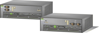
1. Check the packing slip to ensure that all the proper components are present.
2. Ensure that the site is set up properly:
3. Obtain the following equipment:
4. Ensure your safety when installing the Catalyst 2926 series or Catalyst 2926G series switch:
5. Take steps to prevent ESD damage to electronic components by using an ESD wrist strap (see figure)
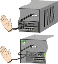
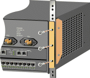
To rack-mount the Catalyst 2926 series or Catalyst 2926G series switch:
Attach the L brackets to the chassis using the four Phillips-head screws provided in the rack-mount kit.

1. With a person on each side of the chassis, lift and position the switch in the equipment rack.
2. Align the holes in the L brackets with the mounting holes in the equipment rack.
3. Insert the mounting screws through the holes in the L brackets and into the threaded holes in the mounting post.
4. Use a level to ensure the chassis is installed straight and level.
To connect the Catalyst 2926 series or Catalyst 2926G series switch to the network:
| Caution To prevent ESD damage to electronic components, always use an ESD wrist strap when handling the switch. |
To connect a terminal to the Catalyst 2926 series supervisor engine console port, plug an EIA/TIA-232 (RS-232) DCE DB-25-to-DTE DB-25 straight-through cable into the console port.
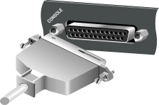
To connect a terminal to the Catalyst 2926G series supervisor engine console port, plug an RJ-45-to-RJ-45 straight-through cable into the console port jack. Use an RJ-45-to-DB-25 or RJ-45-to-DB-9 adapter to connect to the terminal.
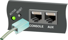
The Catalyst 2926 series and 2926G series modules use the following connection types:
To connect switch ports with RJ-45 interfaces, use Category 5 UTP (100BaseTX, 10/100BaseTX) cables with male RJ-45 interfaces.
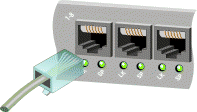
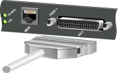
The Catalyst 2926 series supervisor engine has MII uplink ports in addition to RJ-45 ports. To connect to the MII interfaces, use Category 5 UTP cables with male MII connectors.
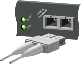
To connect switch ports with SC-type fiber-optic interfaces, use multimode fiber-optic cable with male SC-type connectors.
| Warning Before you work on any equipment, be aware of the hazards involved with electrical circuitry and be familiar with standard practices for preventing accidents. |
| Caution To prevent ESD damage to electronic components, always use an ESD wrist strap when handling the switch. |
1. Attach each power cable to a grounded outlet. If possible, connect each cable to an outlet on a separate circuit. Make sure that the source power is within range.
2. Do not connect the power cables to the power supplies until you are ready to boot the switch.
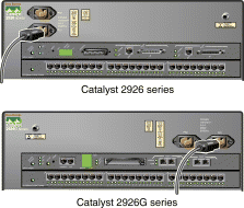
1. Before you start the system, verify the following:
2. To power up the switch, plug the power cables into the power supplies. The switch begins the boot process.
3. During the boot process:
4. Press Return at the Enter Password prompt to access the console command line.
|
|