|
|


Catalyst 2900 series XL switch | |
Catalyst 2900 Series XL Installation and Configuration Guide | |
RJ-45-to-RJ-45 rollover console cable | |
AC power cable | |
RJ-45-to-DB-9 serial connector | |
RJ-45-to-DB-25 terminal connector | |
Rack-mount kit | |
Rubber feet | |

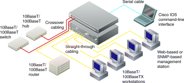
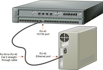
1. Connect a Category 5 straight-through cable (not supplied) to a 10/100 port on the front panel of the switch.
2. Connect the other end of the cable to the RJ-45 port of the PC, workstation, server, or router.
1. Connect a Category 5 crossover cable (not supplied) to a 10/100 port on the front panel of the switch.
2. Connect the other end of the cable to an RJ-45 port of the target switch or hub.

1. Connect one end of the supplied AC power cable to the rear panel of the switch.
2. Connect the other end of the power cable to the AC wall outlet.
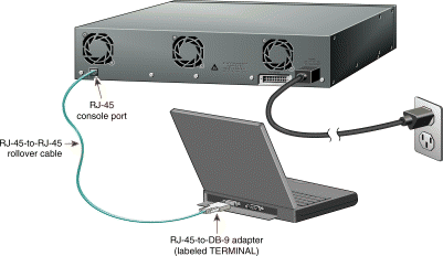
1. Connect the supplied rollover cable to the port marked CONSOLE on the rear panel of the switch.
2. Connect the other end of the cable to a terminal or PC with terminal emulation software. Use one of the supplied adapters if you need to.
The console port has the following data characteristics:
9600 baud
No parity
8 data bits
1 stop bit
You assign IP information to the switch so that the switch can communicate with local routers and the Internet and so that you can use the web-based Cisco Visual Switch Manager Software. The first time you start the switch, it prompts you for an IP address, subnet mask, and default gateway.
Before you start the switch, contact your system administrator to obtain the following information, and record it here:
1. Switch IP address:

2. Subnet mask (IP netmask):

3. Default gateway (router):

Step 1 Enter Y at the first prompt:
Continue with configuration dialog? [yes/no]: y
Step 2 Enter the switch IP address, and press Return:
Enter IP address: 1
Step 3 Next, enter the subnet mask, and press Return:
Enter IP netmask: 2
Step 4 Enter Y at the next prompt to enter a default gateway (router):
Would you like to enter a default gateway address? [yes]: y
Step 5 Enter the IP address of the default gateway, and press Return:
Enter router IP address: 3
The initial configuration displays:
The following configuration command script was created:

interface VLAN1
ip address 172.20.153.36 255.255.255.0
ip default-gateway 172.20.128.1
snmp community private rw
snmp community public ro
end

Use this configuration? [yes/no]:
Step 6 Verify that the IP addresses are correct, and enter Y. If the IP addresses are wrong, enter N to restart the procedure. If the prompt in Step 1 does not appear, enter enable, and then enter setup.
After you have assigned an IP address to the switch, you can use the web-based manager software to view or change configuration settings. You can also use the Cisco IOS command-line interface (CLI) to view parameters and configure the switch.
The manager software supports these platforms and network browsers:
Win95 Win 98 | Netscape Communicator 4.03 or greater1 | Microsoft Internet Explorer 4.012 |
Windows NT | Netscape Communicator 4.03 or greater1 | Microsoft Internet Explorer 4.013 |
Solaris 2.5.1 or greater4 | Netscape Communicator 4.03 or greater |
|
| 1Use Netscape Communicator 4.06 to access the network view. 2Use Microsoft Internet Explorer 4.01 with Service Pack 1 to access the network view. 3Use Microsoft Internet Explorer 4.01 with Service Pack 3. 4Use the SUN-recommended patch cluster for that OS and the Motif library patch 103461-24. |
Follow these steps to display the manager software:
Step 1 Start Netscape Communicator or Internet Explorer.
Step 2 Enable browser options needed to communicate with the switch.
1. Select View>Internet Options>Advanced tab.
2. Scroll through the list of options until you see Java VM, then select the Java JIT compiler enabled and Java logging enabled check boxes.
3. Click Apply.
4. Select the General tab and click Settings. Click Every visit to the page.
5. Click OK.
1. Select Edit>Preferences>Advanced.
2. Select the Enable Java, Enable JavaScript, and Enable style-sheets check boxes.
3. Click OK to return to the browser home page.
4. Click Edit>Preferences again and access the Advanced>Cache option.
5. Select Every time.
6. Click OK.
Step 3 Enter the IP address of the switch in the Location field (the Address field if you are using Internet Explorer).
Step 4 Press Return. The universal access page for your switch displays.

Step 5 Click Visual Switch Manager to display the manager home page.
The Catalyst 2900 Series XL Installation and Configuration Guide provides detailed instructions for using the Cisco Visual Switch Manager Software and the
Cisco IOS CLI for configuring your Cisco 2900 series XL switch. See Release Notes for the Catalyst 2900 Series XL Cisco IOS Release 11.2(8)SA3 for additional information about Internet Explorer security settings and late-breaking information about the Catalyst 2900 Series XL switch.
![]()
![]()
![]()
![]()
![]()
![]()
![]()
![]()
Posted: Tue May 11 12:16:07 PDT 1999
Copyright 1989-1999©Cisco Systems Inc.