|
|


Catalyst 3500 series XL switch | |
Catalyst 3500 Series XL Installation Guide and Release Notes for Catalyst 2900 Series XL and Catalyst 3500 Series XL Cisco | |
RJ-45-to-RJ-45 rollover console cable | |
AC power cable | |
RJ-45-to-DB-9 serial connector | |
RJ-45-to-DB-25 terminal connector | |
Rack-mount kit | |
Rubber feet | |

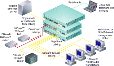
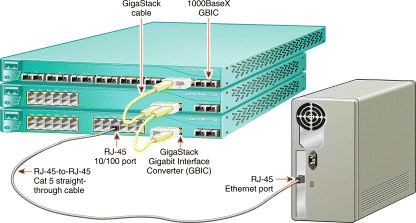
1. Connect a Category 5 straight-through cable (not supplied) to a 10/100 port on the front panel of the switch.
2. Connect the other end of the cable to the RJ-45 port of the PC, workstation, server, or router.
1. Connect a Category 5 crossover cable (not supplied) to a 10/100 port on the front panel of the switch.
2. Connect the other end of the cable to an RJ-45 port of the target switch or hub.
1. Insert the GigaStack GBICs in the GBIC module slots on the switches.
2. Connect the GigaStack GBICs using the Cisco proprietary GigaStack cable.

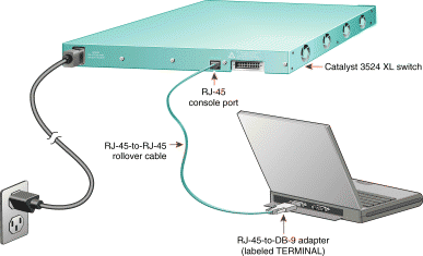
1. Connect one end of the supplied AC power cable to the rear panel of the switch.
2. Connect the other end of the power cable to a grounded AC wall outlet.
1. Connect the supplied flat, blue rollover cable to the port marked CONSOLE on the rear panel of the switch.
2. Connect the other end of the cable to a terminal or PC with terminal emulation software. Use one of the supplied adapters if you need to.
The console port has the following data characteristics:
9600 baud
No parity
8 data bits
1 stop bit
If you are configuring this switch as a cluster member, Section 3, "Assign IP Information to the Switch," and Section 4, "Display the Cisco Visual Switch Manager Software," are not required. (See the Cisco IOS Desktop Switching Software Configuration Guide for details.) In all other cases, you must complete Section 3. (Section 4 is optional.)
Assign the IP information that the switch uses with the local routers and the Internet and that you use with the Cisco Visual Switch Manager (CVSM) software.
Get the following IP information from your system administrator:
Use this procedure to assign IP information:
Step 1 Enter Y at the first prompt:
Continue with configuration dialog? [yes/no]: y
Step 2 Enter the switch IP address, and press Return:
Enter IP address:
1
Step 3 Enter the subnet mask, and press Return:
Enter IP netmask:
2
Step 4 Enter the IP address of your default gateway:
Would you like to enter a default gateway address? [yes]: y
IP address of the default gateway: 3
Step 5 Enter the host name, and press Return:
Enter host name [Switch]:
Step 6 Enter a password, and press Return.
Enter enable secret:
Step 7 Enter Y to configure this switch as the cluster command switch, or enter N to configure it as a standalone or member switch:
Would you like to enable as a cluster command switch? y
Step 8 Assign a name to the cluster:
Enter cluster name? cls_name
Step 9 Your initial configuration displays as follows:
The following configuration command script was created:
interface VLAN1
ip address 172.20.153.36 255.255.255.0
ip default-gateway 172.20.128.1
enable secret 5 $1$M3pS$cXtAlkyR3/6Cn8/
snmp community private rw
snmp community public ro
cluster enable cls_name
end

Use this configuration? [yes/no]:y
Step 10 If this is correct, enter Y; if it is incorrect, enter N to restart the procedure.
After you have assigned an IP address to the switch, you can use CVSM or use the Cisco IOS command-line interface (CLI) to view or change configuration settings.
CVSM supports these platforms and network browsers:
Windows 95 Windows 98 | Netscape Communicator 4.5.1 and 4.5 | Microsoft Internet Explorer 5.0 and 4.01 with Service Pack 1 |
Windows NT | Netscape Communicator 4.5.1 and 4.5 | Microsoft Internet Explorer 5.0 and 4.01 with Service Pack 3 |
Solaris 2.5.1 or greater1 | Netscape Communicator 4.5.1 and 4.5 | Not supported. |
| 1Use the SUN-recommended patch cluster for that OS and the Motif library patch 103461-24. |
Follow these steps to display CVSM:
Step 1 Start Netscape Communicator or Internet Explorer.
Step 2 Enable browser options needed to communicate with the switch.
For Internet Explorer:
1 Select View>Internet Options>Advanced tab.
2 Scroll through the list of options until you see Java VM, and select the Java JIT compiler enabled and the Java logging enabled check boxes.
3 Click Apply.
4 Select the General tab, and click Settings. Click Every visit to the page.
5 Click OK.
For Netscape Communicator:
1 Select Edit>Preferences>Advanced.
2 Select the Enable Java, the Enable JavaScript, and the Enable style-sheets check boxes.
3 Click OK to return to the home page.
4 Click Edit>Preferences>Advanced, and click Cache to display the cache dialog.
5 Select Every time, and click OK.
Step 3 Enter the IP address of the switch in the Location field (the Address field if you are using Internet Explorer).
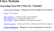
Step 4 Press Return. The universal access page for your switch displays.
Step 5 Click Visual Switch Manager to display the CVSM home page.
See the Catalyst 3500 Series XL Installation Guide for detailed instructions on installing the Cisco 3500 series XL switch. See the Cisco IOS Desktop Switching Software Configuration Guide for instructions on using the CVSM, the Cisco IOS CLI, and the cluster management software to configure and to manage switches. See Release Notes for Catalyst 2900 Series XL and
Catalyst 3500 Series XL Cisco IOS
Release 11.2(8)SA6 for recent information about the Catalyst 3500 series XL switch.
![]()
![]()
![]()
![]()
![]()
![]()
![]()
![]()
Posted: Wed May 26 11:18:17 PDT 1999
Copyright 1989-1999©Cisco Systems Inc.