|
|

Table Of Contents
1000BASE-T GBIC Installation Notes
Connecting to 1000BASE-T Ports
Technical Specifications and Agency Approvals
Obtaining Technical Assistance
Cisco Technical Support Website
Definitions of Service Request Severity
Obtaining Additional Publications and Information
1000BASE-T GBIC Installation Notes
July 2004
These installation notes provide instructions for installing 1000BASE-T Gigabit Interface Converters (GBICs) in Catalyst 2900 XL, Catalyst 2950, Catalyst 3500 XL, Catalyst 3550, Catalyst 4000 family, and Catalyst 6000 family switches and provide troubleshooting information.
The1000BASE-T GBICs are hot-swappable, single-port modules. They provide 1000BASE-T full-duplex connectivity in Catalyst 2900 XL switches, Catalyst 2950 switches, Catalyst 3500 XL switches, Catalyst 3550 switches, Catalyst 4000 family switches, Catalyst 6000 family switches, and other 1000BASE-T-compatible devices in the online 1000BASE-T GBIC Switch Compatibility Matrix, which is posted with the GBIC documentation on Cisco.com.
For information about installing the 1000BASE-T GBICs in other 1000BASE-T-compatible devices, refer to the documentation for those devices.
Contents
This document has these sections:
•
"Technical Specifications and Agency Approvals" section
•
•
•
•
Conventions
This document uses these conventions and symbols for notes, cautions, and warnings:
Note
Caution
Description
The single-port 1000BASE-T GBIC (model WS-G5482 or WS-G5483) has these features:
•
•
The GBIC supports automatic medium-dependent interface crossover (Auto-MDIX). The GBIC automatically detects the required cable connection type (straight through or crossover) and configures the connection appropriately.
Caution
Caution
Note
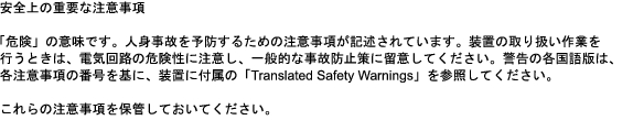
Figure 1 shows the 1000BASE-T GBIC.
Figure 1 1000BASE-T GBIC
Supported Switches
For a list of the switches and switching modules that support the GBIC, refer to the online 1000BASE-T GBIC Switch Compatibility Matrix. The switches detect and enable the GBIC only when they are running the minimum software releases in the list.
For example, if your Catalyst 2900 XL or 3500 XL switch is running Cisco IOS Release 12.0(5)XW or later, it detects and enables the WS-G5482 GBIC. You can manage this GBIC by using the CLI or the Cluster Management Suite (CMS). If the switch is running a Cisco IOS release earlier than Cisco IOS Release 12.0(5)XW, it does not detect and enable this GBIC. You must upgrade your software to Cisco IOS Release 12.0(5)XW or later. To upgrade to Cisco IOS Release 12.0(5)XW or later, refer to the release notes for the upgrade procedures. After you upgrade the software, the switch detects and enables the GBIC.
If your Catalyst 2900 XL or 3500 XL switch is running Cisco IOS Release 12.0(5)WC3 or later, it also detects and enables the WS-G5483 GBIC. You can manage this GBIC by using the CLI or the CMS. If the switch is running a Cisco IOS release earlier than Cisco IOS Release 12.0(5)WC3, it does not detect and enable this GBIC. You must upgrade your software to Cisco IOS Release 12.0(5)WC3 or later. To upgrade to Cisco IOS Release 12.0(5)WC3 or later, refer to the release notes for the upgrade procedures. After you upgrade the software, the switch detects and enables the GBIC.
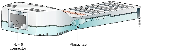
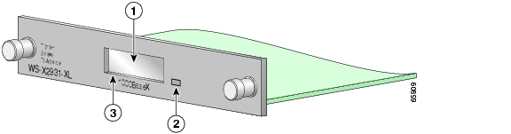
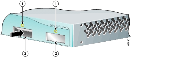
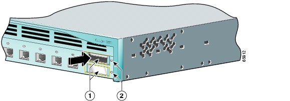
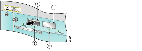
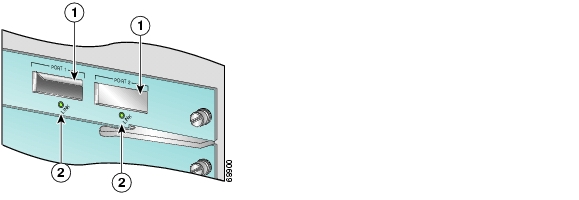
Figure 2 shows the GBIC slot in a 1000BASE-X module for a Catalyst 2900 XL switch. Figure 3 shows the GBIC slots in a Catalyst 2950 switch front panel. Figure 4 shows the GBIC slots in a Catalyst 3500 XL switch front panel. Figure 5 shows the GBIC slots in a Catalyst 3550 switch front panel. Figure 6 shows the GBIC slots in a Catalyst 4006 supervisor-engine front panel. Figure 7 shows the GBIC slots in a Catalyst 6000 family supervisor-engine front panel.
Figure 2 GBIC Slot in a 1000BASE-X Module for a Catalyst 2900 XL Switch
Figure 3 GBIC Slots in a Catalyst 2950 Switch Front Panel
Figure 4 GBIC Slots in a Catalyst 3500 XL Switch Front Panel
Figure 5 GBIC Slots in a Catalyst 3550 Switch Front Panel
Figure 6 GBIC Slots in a Catalyst 4006 Supervisor-Engine Front Panel
Figure 7 GBIC Slots in a Catalyst 6000 Family Supervisor-Engine Front Panel
LEDs
The 1000BASE-X GBIC module for a Catalyst 2900 XL switch has an LED that displays information about the GBIC port. Table 1 explains how to interpret the LED colors. Refer to the Catalyst 2900 Series XL Modules Installation Guide and the Catalyst 2900 Series XL Hardware Installation Guide for more information about the 1000BASE-X modules.
The GBIC LEDs on the Catalyst 2950, Catalyst 3500 XL, and Catalyst 3550 switch front panels, as a group or individually, display information about the switch and the individual ports. When you change the port mode, the meanings of the LED colors change. Table 2 explains how to interpret the LED colors when you change the port mode to STAT (port status). Refer to the hardware documentation that came with your switch for more information about the GBICs.
The GBIC LEDs on the Catalyst 4006 and the Catalyst 6000 family supervisor-engine or switching-module front panels, as a group or individually, display information about the switch and the individual ports. Table 3 explains how to interpret the LED colors. Refer to the hardware documentation that came with your switch for more information about the GBICs.
Table 1 Meaning of 1000BASE-X Module LED Colors on Catalyst 2900 XL Switches
Off
No link.
Green
Link present.
Flashing green
Activity. GBIC port is sending or receiving data.
Alternating green-amber
Link fault. Error frames can affect connectivity, and errors such as excessive collisions, CRC1 errors, and alignment and jabber errors are monitored for a link-fault indication.
Amber
GBIC port is not forwarding because the port was disabled or the module failed POST2 . The port could be disabled by management, an address violation, or STP3 . If the module failed POST, it should be replaced.
Note
1 CRC = cyclic redundancy check
2 POST = power-on self-test
3 STP = Spanning Tree Protocol
Installation
This section describes how to install your 1000BASE-T GBIC.
EMC Regulatory Statements
This section includes specific regulatory statements about the 1000BASE-T GBIC.
U.S.A.
U.S. regulatory information for this product is at the end of this document.
Taiwan
Japan
Korea
Hungary
Installation Guidelines
When installing the GBIC in Catalyst 2950, Catalyst 4000 family, and Catalyst 6000 family switches, follow these guidelines:
•
•
Caution
Cabling Guidelines
Caution
The GBIC supports Auto-MDIX. The GBIC port uses an RJ-45 connector and four twisted-pair, Category 5 cabling.
The port can be connected to a 1000BASE-T-compatible device, such as a high-speed workstation, server, hub, router, or other switch. You can use a straight-through or a crossover cable to connect to other devices, and the interface automatically corrects for any incorrect cabling. The cable length from the GBIC to an attached device cannot exceed 328 feet (100 meters).
For connector pinouts and cable specifications, see the "Connectors and Cables" section.
For more information, refer to the hardware and software documentation for the connected device.
Handling the GBIC
Follow these guidelines when handling a GBIC:
•
•
Inserting the GBIC
Gigabit Ethernet devices are shipped without the GBIC installed.
Caution
GBICs are hot-swappable and are designed to prevent incorrect insertion.
Follow these steps to insert the GBIC in a GBIC or module slot:
Step 1
Step 2
Step 3
If the GBIC is not inserted securely (not locked in the slot), the switch might not recognize it or might display the wrong media type after you enter the show interface privileged EXEC command on the Cisco IOS CLI or the show port command on the Catalyst software CLI. If this happens, remove and reinsert the GBIC. See the "Troubleshooting" section for more information.
To connect a 1000BASE-T-compatible device to the GBIC, see the "Connecting to 1000BASE-T Ports" section.
Removing the GBIC
To remove the GBIC from the GBIC slot, disconnect the cable from the RJ-45 connector on the GBIC. Release the GBIC from the slot by simultaneously squeezing the two plastic tabs, and pull out the GBIC.
Connecting to 1000BASE-T Ports
Caution
Caution
Step 1
Step 2
Step 3
The LED turns green when the GBIC and the target device have an established link.
The LED turns amber while STP discovers the network topology and searches for loops. This process takes about 30 seconds, and then the LED turns green.
If the LED is off, the target device might not be turned on, there might be a cable problem, or there might be a problem with the adapter installed in the target device. See the "Troubleshooting" section for solutions to cabling problems.
Step 4
Where to Go Next
Caution
The GBIC only supports 1000-Mbps full-duplex connections. If the port configuration settings are changed, the switch does not detect and enable the GBIC. An error message appears in the CLI, the Catalyst software CLI, or the CMS.
The Catalyst 2900 XL, Catalyst 2950, Catalyst 3500 XL, Catalyst 3550, Catalyst 4000 family, and Catalyst 6000 family switches detect and enable the GBIC only when they are running the minimum software releases listed in online 1000BASE-T GBIC Compatibility Matrix.
Troubleshooting
These tables describe how to detect and solve problems that might arise when you are installing the GBIC. If you are installing the GBIC in a 1000BASE-X module for a Catalyst 2900 XL switch, see Table 4. If you are installing the GBIC in a Catalyst 2950, Catalyst 3500 XL, or Catalyst 3550 switch, see Table 5. For more information, refer to the documentation that came with your switch or module.
If you are installing the GBIC in a Catalyst 4000 family or Catalyst 6000 family switch, refer to the hardware documentation that came with your switch or module for troubleshooting information.
Technical Specifications and Agency Approvals
Table 6 lists the technical specifications and agency approvals.
Connectors and Cables
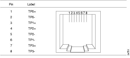
The GBIC port uses a standard RJ-45 connector. Figure 8 shows the pinout.
Figure 9 shows the straight-through cable schematics.
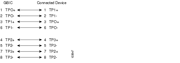
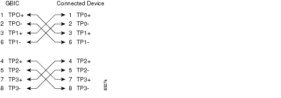
Figure 10 shows the crossover cable schematics.
Figure 8 1000BASE-T RJ-45 Connector
Figure 9 Straight-Through Cable Schematic
Figure 10 Crossover Cable Schematics
Related Publications
These documents provide complete information about the GBIC and the switches and modules supporting it and are available from this URL:
http://www.cisco.com/univercd/home/home.htm
You can order printed copies of documents with a DOC-xxxxxx= number from the Cisco.com sites and from the telephone numbers listed in the "Obtaining Documentation" section.
•
Note
•
•
•
•
•
•
•
•
•
•
•
•
•
•
•
•
Obtaining Documentation
Cisco documentation and additional literature are available on Cisco.com. Cisco also provides several ways to obtain technical assistance and other technical resources. These sections explain how to obtain technical information from Cisco Systems.
Cisco.com
You can access the most current Cisco documentation at this URL:
http://www.cisco.com/univercd/home/home.htm
You can access the Cisco website at this URL:
You can access international Cisco websites at this URL:
http://www.cisco.com/public/countries_languages.shtml
Ordering Documentation
You can find instructions for ordering documentation at this URL:
http://www.cisco.com/univercd/cc/td/doc/es_inpck/pdi.htm
You can order Cisco documentation in these ways:
•
http://www.cisco.com/en/US/partner/ordering/index.shtml
•
Documentation Feedback
You can send comments about technical documentation to bug-doc@cisco.com.
You can submit comments by using the response card (if present) behind the front cover of your document or by writing to the following address:
Cisco Systems
Attn: Customer Document Ordering
170 West Tasman Drive
San Jose, CA 95134-9883We appreciate your comments.
Obtaining Technical Assistance
For all customers, partners, resellers, and distributors who hold valid Cisco service contracts, Cisco Technical Support provides 24-hour-a-day, award-winning technical assistance. The Cisco Technical Support Website on Cisco.com features extensive online support resources. In addition, Cisco Technical Assistance Center (TAC) engineers provide telephone support. If you do not hold a valid Cisco service contract, contact your reseller.
Cisco Technical Support Website
The Cisco Technical Support Website provides online documents and tools for troubleshooting and resolving technical issues with Cisco products and technologies. The website is available 24 hours a day, 365 days a year at this URL:
http://www.cisco.com/techsupport
Access to all tools on the Cisco Technical Support Website requires a Cisco.com user ID and password. If you have a valid service contract but do not have a user ID or password, you can register at this URL:
http://tools.cisco.com/RPF/register/register.do
Submitting a Service Request
Using the online TAC Service Request Tool is the fastest way to open S3 and S4 service requests. (S3 and S4 service requests are those in which your network is minimally impaired or for which you require product information.) After you describe your situation, the TAC Service Request Tool automatically provides recommended solutions. If your issue is not resolved using the recommended resources, your service request will be assigned to a Cisco TAC engineer. The TAC Service Request Tool is located at this URL:
http://www.cisco.com/techsupport/servicerequest
For S1 or S2 service requests or if you do not have Internet access, contact the Cisco TAC by telephone. (S1 or S2 service requests are those in which your production network is down or severely degraded.) Cisco TAC engineers are assigned immediately to S1 and S2 service requests to help keep your business operations running smoothly.
To open a service request by telephone, use one of the following numbers:
Asia-Pacific: +61 2 8446 7411 (Australia: 1 800 805 227)
EMEA: +32 2 704 55 55
USA: 1 800 553 2447For a complete list of Cisco TAC contacts, go to this URL:
http://www.cisco.com/techsupport/contacts
Definitions of Service Request Severity
To ensure that all service requests are reported in a standard format, Cisco has established severity definitions.
Severity 1 (S1)—Your network is "down," or there is a critical impact to your business operations. You and Cisco will commit all necessary resources around the clock to resolve the situation.
Severity 2 (S2)—Operation of an existing network is severely degraded, or significant aspects of your business operation are negatively affected by inadequate performance of Cisco products. You and Cisco will commit full-time resources during normal business hours to resolve the situation.
Severity 3 (S3)—Operational performance of your network is impaired, but most business operations remain functional. You and Cisco will commit resources during normal business hours to restore service to satisfactory levels.
Severity 4 (S4)—You require information or assistance with Cisco product capabilities, installation, or configuration. There is little or no effect on your business operations.
Obtaining Additional Publications and Information
Information about Cisco products, technologies, and network solutions is available from various online and printed sources.
•
http://www.cisco.com/go/marketplace/
•
http://cisco.com/univercd/cc/td/doc/pcat/
•
•
•
http://www.cisco.com/go/iqmagazine
•
•
http://www.cisco.com/en/US/learning/index.html
THE SPECIFICATIONS AND INFORMATION REGARDING THE PRODUCTS IN THIS MANUAL ARE SUBJECT TO CHANGE WITHOUT NOTICE. ALL STATEMENTS, INFORMATION, AND RECOMMENDATIONS IN THIS MANUAL ARE BELIEVED TO BE ACCURATE BUT ARE PRESENTED WITHOUT WARRANTY OF ANY KIND, EXPRESS OR IMPLIED. USERS MUST TAKE FULL RESPONSIBILITY FOR THEIR APPLICATION OF ANY PRODUCTS.
THE SOFTWARE LICENSE AND LIMITED WARRANTY FOR THE ACCOMPANYING PRODUCT ARE SET FORTH IN THE INFORMATION PACKET THAT SHIPPED WITH THE PRODUCT AND ARE INCORPORATED HEREIN BY THIS REFERENCE. IF YOU ARE UNABLE TO LOCATE THE SOFTWARE LICENSE OR LIMITED WARRANTY, CONTACT YOUR CISCO REPRESENTATIVE FOR A COPY.
The following information is for FCC compliance of Class A devices: This equipment has been tested and found to comply with the limits for a Class A digital device, pursuant to part 15 of the FCC rules. These limits are designed to provide reasonable protection against harmful interference when the equipment is operated in a commercial environment. This equipment generates, uses, and can radiate radio-frequency energy and, if not installed and used in accordance with the instruction manual, may cause harmful interference to radio communications. Operation of this equipment in a residential area is likely to cause harmful interference, in which case users will be required to correct the interference at their own expense.
The following information is for FCC compliance of Class B devices: The equipment described in this manual generates and may radiate radio-frequency energy. If it is not installed in accordance with Cisco's installation instructions, it may cause interference with radio and television reception. This equipment has been tested and found to comply with the limits for a Class B digital device in accordance with the specifications in part 15 of the FCC rules. These specifications are designed to provide reasonable protection against such interference in a residential installation. However, there is no guarantee that interference will not occur in a particular installation.
Modifying the equipment without Cisco's written authorization may result in the equipment no longer complying with FCC requirements for Class A or Class B digital devices. In that event, your right to use the equipment may be limited by FCC regulations, and you may be required to correct any interference to radio or television communications at your own expense.
You can determine whether your equipment is causing interference by turning it off. If the interference stops, it was probably caused by the Cisco equipment or one of its peripheral devices. If the equipment causes interference to radio or television reception, try to correct the interference by using one or more of the following measures:
Ζ Turn the television or radio antenna until the interference stops.
Ζ Move the equipment to one side or the other of the television or radio.
Ζ Move the equipment farther away from the television or radio.
Ζ Plug the equipment into an outlet that is on a different circuit from the television or radio. (That is, make certain the equipment and the television or radio are on circuits controlled by different circuit breakers or fuses.)
Modifications to this product not authorized by Cisco Systems, Inc. could void the FCC approval and negate your authority to operate the product.
The Cisco implementation of TCP header compression is an adaptation of a program developed by the University of California, Berkeley (UCB) as part of UCB's public domain version of the UNIX operating system. All rights reserved. Copyright © 1981, Regents of the University of California.
NOTWITHSTANDING ANY OTHER WARRANTY HEREIN, ALL DOCUMENT FILES AND SOFTWARE OF THESE SUPPLIERS ARE PROVIDED "AS IS" WITH ALL FAULTS. CISCO AND THE ABOVE-NAMED SUPPLIERS DISCLAIM ALL WARRANTIES, EXPRESSED OR IMPLIED, INCLUDING, WITHOUT LIMITATION, THOSE OF MERCHANTABILITY, FITNESS FOR A PARTICULAR PURPOSE AND NONINFRINGEMENT OR ARISING FROM A COURSE OF DEALING, USAGE, OR TRADE PRACTICE.
IN NO EVENT SHALL CISCO OR ITS SUPPLIERS BE LIABLE FOR ANY INDIRECT, SPECIAL, CONSEQUENTIAL, OR INCIDENTAL DAMAGES, INCLUDING, WITHOUT LIMITATION, LOST PROFITS OR LOSS OR DAMAGE TO DATA ARISING OUT OF THE USE OR INABILITY TO USE THIS MANUAL, EVEN IF CISCO OR ITS SUPPLIERS HAVE BEEN ADVISED OF THE POSSIBILITY OF SUCH DAMAGES.
This document is to be used in conjunction with the documents listed in the "Related Publications" section.
Copyright © 2001-2004 Cisco Systems, Inc. All rights reserved.
![]()
![]()
![]()
![]()
![]()
![]()
![]()
![]()
Posted: Thu Jul 15 13:37:15 PDT 2004
All contents are Copyright © 1992--2004 Cisco Systems, Inc. All rights reserved.
Important Notices and Privacy Statement.