|
|

This appendix describes the connectors for the EtherSwitch 1420 FDDI and 100BaseT modules.
This section describes the following connectors:
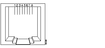
The UTP SAS module uses standard RJ-45 connectors. The connector and the arrangement of the pins is shown in Figure B-1. The pinout is shown in Table B-1.
Note that connector shells are attached to the chassis ground. Stations are always attached with a crossover cable.

| Pin | Description |
|---|---|
| 1 | TX+ |
| 2 | TX- |
| 3 | NC |
| 4 | NC |
| 5 | NC |
| 6 | NC |
| 7 | RX+ |
| 8 | RX- |
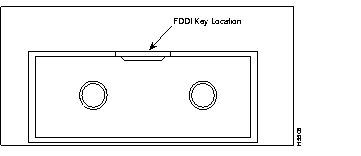
The FDDI module uses standard MIC connectors, as shown in Figure B-2.

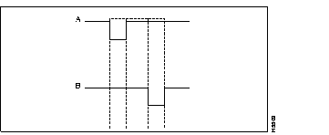
The receptacle keys for ports A and B of the FDDI Fiber DAS module are shown in a simplified form in Figure B-3.

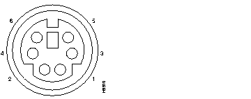
The FDDI Fiber DAS module uses a 6-pin mini-DIN connector for the optical bypass switch. The connector is shown in Figure B-4, and the pin arrangement is shown in Table B-2.

| Pin | Description |
|---|---|
| 1 | +5V secondary switch |
| 2 | +5V primary switch |
| 3 | GND primary switch |
| 4 | GND secondary switch |
| 5 | Optical bypass presence-sense return |
| 6 | Optical bypass presence sense |
This section describes the 100BaseTX (RJ-45) and 100BaseFX (ST) connectors for the EtherSwitch 1420 100BaseT modules.
The 100BaseTX modules use standard RJ-45 connectors. The arrangement of the pins is shown in Figure B-5, and the pinout is shown in Table B-3.

| Pin | Description |
|---|---|
| 1 | RD+ |
| 2 | RD- |
| 3 | TD+ |
| 4 | NC |
| 5 | NC |
| 6 | TD- |
| 7 | NC |
| 8 | NC |
Connector shells are attached to the chassis ground. The 100BaseTX ports have the transmit (TD) and receive (RD) pairs internally crossed (as shown in Figure B-7) for attachment to an adapter using a straight-through cable.
The straight-through and crossover cable schematics are shown in Figure B-6 and Figure B-7.


The 100BaseFX modules use standard ST connectors, as shown in Figure B-8.

|
|