|
|

Table Of Contents
Cisco IP/VC 3544 Chassis Replacement Power Supply Unit Release Note
Installation and Replacement Procedure
Determining that a Power Supply Has Failed
Obtaining Technical Assistance
Cisco IP/VC 3544 Chassis Replacement Power Supply Unit Release Note
March, 2001
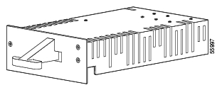
This document describes how to install a replacement power supply unit (see Figure 1) in the IP/VC 3544 chassis.
Figure 1 Cisco IP/VC 3544 Replacement Power Supply
The IP/VC 3544 chassis uses two power supply units (PSU) to provide fault-tolerant operation. This design ensures that the IP/VC 3540 modules installed in the chassis continue to run without interruption should one of the PSUs fail. The system uses the Power LED to alert the IP/VC 3540 administrator of a PSU failure and provides two places to monitor this LED: a Power LED located on the chassis front panel for direct monitoring and the IP/VC Administrator System Web page remote monitoring. You can replace the PSU without interrupting videoconference operations.
For regulatory and compliance information on the Cisco IP/VC 3544, refer to the Regulatory Compliance and Safety Information for Cisco IP/VC 3540 Series document.
Contents
These release notes discuss the following topics:
•
Installation and Replacement Procedure
•
Documentation Roadmap
Use these documents to learn how to use the IP/VC 3544 chassis and for regulatory and compliance information about IP/VC 3540 products:
•
•
Power Supply Features
The IP/VC 3544 chassis PSU has the following features:
•
•
•
•
•
•
Installation and Replacement Procedure
This section describes how to determine that a power supply unit has failed and how to replace it.
Warning
Determining that a Power Supply Has Failed
The Cisco IP/VC 3544 chassis monitors PSU operations and uses the Power LED to alert the system administrator when one of the PSUs fail. The Power LED appears in two places: on the IP/VC 3544 chassis front panel and on the IP/VC Administrator System Web page. The Power LED is red in both places when a PSU fails and green when both PSUs are operating.
To use the IP/VC Administrator System Web page to view the Power LED from a remote site, perform the following steps:
Step 1
Step 2
IP address/admin
where IP address is the IP address assigned to the IP/VC 3540 system module installed in the chassis you want to monitor. The IP/VC Administrator login page appears.
Step 3
The IP/VC Administrator page appears.
Step 4
The IP/VC Administrator System page appears.
Step 5
The LED is red when a PSU has failed. The LED is green when both PSUs are operating.
Replacing a Power Supply
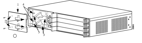
You can replace a PSU that has failed without disrupting the power to the chassis. To replace the failed PSU, perform the following steps:
Step 1
Note
Figure 2 Removing the Power Supply Unit
Step 2
Step 3
Note
Step 4
Use firm and even pressure to ensure that the PSU connector engages properly with the connector inside the slot. The replacement PSU is properly connected when the face plate is flush with the chassis bay.
Step 5
Step 6
Warning
Warning
Service and Support
For service and support, contact Cisco Technical Assistance Center (TAC) at:
http://www.cisco.com/warp/public/687/Directory/DirTAC.shtml
Obtaining Documentation
The following sections provide sources for obtaining documentation from Cisco Systems.
World Wide Web
You can access the most current Cisco documentation on the World Wide Web at the following sites:
•
•
•
Documentation CD-ROM
Cisco documentation and additional literature are available in a CD-ROM package, which ships with your product. The Documentation CD-ROM is updated monthly and may be more current than printed documentation. The CD-ROM package is available as a single unit or as an annual subscription.
Ordering Documentation
Cisco documentation is available in the following ways:
•
http://www.cisco.com/cgi-bin/order/order_root.pl
•
http://www.cisco.com/go/subscription
•
Documentation Feedback
If you are reading Cisco product documentation on the World Wide Web, you can submit technical comments electronically. Click Feedback in the toolbar and select Documentation. After you complete the form, click Submit to send it to Cisco.
You can e-mail your comments to bug-doc@cisco.com.
To submit your comments by mail, use the response card behind the front cover of your document, or write to the following address:
Attn Document Resource Connection
Cisco Systems, Inc.
170 West Tasman Drive
San Jose, CA 95134-9883We appreciate your comments.
Obtaining Technical Assistance
Cisco provides Cisco.com as a starting point for all technical assistance. Customers and partners can obtain documentation, troubleshooting tips, and sample configurations from online tools. For Cisco.com registered users, additional troubleshooting tools are available from the TAC website.
Cisco.com
Cisco.com is the foundation of a suite of interactive, networked services that provides immediate, open access to Cisco information and resources at anytime, from anywhere in the world. This highly integrated Internet application is a powerful, easy-to-use tool for doing business with Cisco.
Cisco.com provides a broad range of features and services to help customers and partners streamline business processes and improve productivity. Through Cisco.com, you can find information about Cisco and our networking solutions, services, and programs. In addition, you can resolve technical issues with online technical support, download and test software packages, and order Cisco learning materials and merchandise. Valuable online skill assessment, training, and certification programs are also available.
Customers and partners can self-register on Cisco.com to obtain additional personalized information and services. Registered users can order products, check on the status of an order, access technical support, and view benefits specific to their relationships with Cisco.
To access Cisco.com, go to the following website:
http://www.cisco.com
Technical Assistance Center
The Cisco TAC website is available to all customers who need technical assistance with a Cisco product or technology that is under warranty or covered by a maintenance contract.
Contacting TAC by Using the Cisco TAC Website
If you have a priority level 3 (P3) or priority level 4 (P4) problem, contact TAC by going to the TAC website:
http://www.cisco.com/tac
P3 and P4 level problems are defined as follows:
•
•
In each of the above cases, use the Cisco TAC website to quickly find answers to your questions.
To register for Cisco.com, go to the following website:
http://www.cisco.com/register/
If you cannot resolve your technical issue by using the TAC online resources, Cisco.com registered users can open a case online by using the TAC Case Open tool at the following website:
http://www.cisco.com/tac/caseopen
Contacting TAC by Telephone
If you have a priority level 1(P1) or priority level 2 (P2) problem, contact TAC by telephone and immediately open a case. To obtain a directory of toll-free numbers for your country, go to the following website:
http://www.cisco.com/warp/public/687/Directory/DirTAC.shtml
P1 and P2 level problems are defined as follows:
•
•
This document is to be used in conjunction with the Cisco IP/VC 3544 Chassis Administrator Guide
AccessPath, AtmDirector, Browse with Me, CCDA, CCDE, CCDP, CCIE, CCNA, CCNP, CCSI, CD-PAC, CiscoLink, the Cisco NetWorks logo, the Cisco Powered Network logo, Cisco Systems Networking Academy, the Cisco Systems Networking Academy logo, Fast Step, Follow Me Browsing, FormShare, FrameShare, GigaStack, IGX, Internet Quotient, IP/VC, iQ Breakthrough, iQ Expertise, iQ FastTrack, the iQ Logo, iQ Net Readiness Scorecard, MGX, the Networkers logo, Packet, PIX, RateMUX, ScriptBuilder, ScriptShare, SlideCast, SMARTnet, TransPath, Unity, Voice LAN, Wavelength Router, and WebViewer are trademarks of Cisco Systems, Inc.; Changing the Way We Work, Live, Play, and Learn, Discover All That's Possible, and Empowering the Internet Generation, are service marks of Cisco Systems, Inc.; and Aironet, ASIST, BPX, Catalyst, Cisco, the Cisco Certified Internetwork Expert logo, Cisco IOS, the Cisco IOS logo, Cisco Systems, Cisco Systems Capital, the Cisco Systems logo, Enterprise/Solver, EtherChannel, EtherSwitch, FastHub, FastSwitch, IOS, IP/TV, LightStream, MICA, Network Registrar, Post-Routing, Pre-Routing, Registrar, StrataView Plus, Stratm, SwitchProbe, TeleRouter, and VCO are registered trademarks of Cisco Systems, Inc. or its affiliates in the U.S. and certain other countries.
All other brands, names, or trademarks mentioned in this document or Web site are the property of their respective owners. The use of the word partner does not imply a partnership relationship between Cisco and any other company. (0102R)
Copyright © 2001, Cisco Systems, Inc.
All rights reserved.
![]()
![]()
![]()
![]()
![]()
![]()
![]()
![]()
Posted: Thu Mar 3 14:25:45 PST 2005
All contents are Copyright © 1992--2005 Cisco Systems, Inc. All rights reserved.
Important Notices and Privacy Statement.