|
|

Table Of Contents
LocalDirector Hardware Platforms
LocalDirector Hardware
This chapter describes LocalDirector hardware platforms, including interface cards. This chapter contains the following sections:
•
LocalDirector Hardware Platforms
LocalDirector Hardware Platforms
LocalDirector introduced the 430 and 416 hardware platforms in version 2.2.1. Support for the previous LocalDirector hardware platforms (the 410, 415, and 420, fully described in Version 2.1 of this guide) continues. shows the features offered by the 416 and 430 platforms.
Table 2-1 LocalDirector Hardware Platform Comparison
384 MB RAM
32 MB RAM
2 MB Flash memory
2 MB Flash memory
One 4-port 10/100 Ethernet interface card
Three 10/100 Ethernet ports
LocalDirector 430 (LDIR-430)
LocalDirector 430 includes:
•
•
•
•
•
•
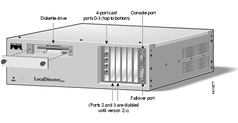
The front panel of LocalDirector 430 is shown in . Note that the diskette drive, interfaces, console port, and failover port are accessed from the front panel.
Figure 2-1 LocalDirector 430 Front Panel
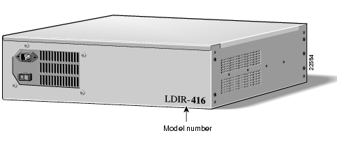
The back panel of both the LocalDirector 430 and 416 are shown in . The power cord receptacle and power switch are located at the back of the units.
Figure 2-2 LocalDirector 430 and 416 Back Panel
LocalDirector 416 (LDIR-416)
LocalDirector 416 includes:
•
•
•
•
•
•
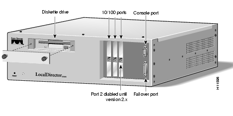
The front panel of LocalDirector 416 is shown in .
Figure 2-3 LocalDirector 416 Front Panel
Rack-Mount Brackets
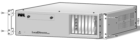
Rack-mount brackets are optional on LocalDirector 430 and 416. shows you how to attach the brackets.
Figure 2-4 Attaching Rack-Mount Brackets
Supported Interfaces
shows the interfaces that are supported on LocalDirector platforms.
Table 2-2 Supported Interfaces by Platform
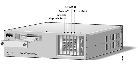
Interface Numbering
Interfaces on LocalDirector models are numbered left to right, top to bottom. shows the interface numbering for a LocalDirector 430 with four 4-port Ethernet interface cards installed.
Figure 2-5 Interface Numbering for LocalDirector 430
4-Port Interface Cards
One 4-port Ethernet card is shipped standard with LocalDirector 430. Up to three more
4-port Ethernet cards can be added.LocalDirector supports two types of 4-port Ethernet cards. To check the type of card you have, use the show interface command. The output of the command tells which type of card you have. describes the types of 4-port Ethernet cards that ship with LocalDirector.
LEDs for Intel Ethernet Cards
Each interface port has two green LEDs. The following describes the two LEDs on the Intel Ethernet 4-port interface cards:
•
•
LEDs for RNS Ethernet Cards
Each interface port has two LEDs, one amber and one green. explains the states of the LEDs on the 4-port interface cards.
•
•
•
Note
Table 2-4 4-Port Interface LEDs
Note
Autonegotiation
The 4-port rns23x0 Ethernet card does not accept the auto option with the interface ethernet command, and returns the following error message:
ERROR: this port does not have autonegotiation capability.The ports on the 4-port rns23x0 Ethernet card default to 100BaseTX. The 10baset, 100basetx, and 100full options are available, but the auto option is not.
If the peer port autonegotiates, the 4-port rns23x0 Ethernet interface speed must be set with the 10baset or 100basetx options; setting it to 100full confuses the autonegotiation process on the peer port, resulting in unpredictable behavior.
The LocalDirector 416 single-port Ethernet card and the LocalDirector 430 i82557 Ethernet card perform autonegotiation, but your network interface must support autodetection.
Note
FDDI Interfaces
FDDI interface cards are optional on LocalDirector 430, and they cannot be mixed with Ethernet interfaces. FDDI interface cards support SMT 7.3.
An easy way to understand FDDI topology is to disregard the dual-attached interfaces. Treat dual-attached interfaces like single-attached interfaces; then treat FDDI like Ethernet; then the network topology looks like an Ethernet topology. Once the topology is determined, put the dual-attached interfaces back into the mix by keeping in mind that the dual-attached interfaces only provide topology redundancy—if a wire is cut, you have another wire to use as a backup. It does not mean you can attach additional servers because you have extra ports.
When installed in LocalDirector, port A is on the bottom of the interface, and port B is on the top as shown in .
Figure 2-6 LocalDirector FDDI Interfaces
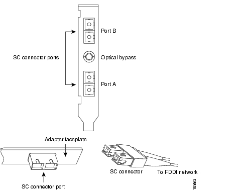
FDDI interface boards for LocalDirector have dual-attached SC connectors as shown in .
Figure 2-7 LocalDirector FDDI Connectors
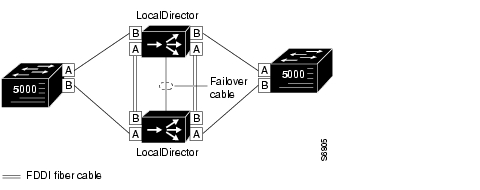
shows a LocalDirector failover implementation with FDDI interfaces.
Figure 2-8 LocalDirector Failover Implementation with FDDI
Note
![]()
![]()
![]()
![]()
![]()
![]()
![]()
![]()
Posted: Wed Nov 10 22:59:10 PST 2004
All contents are Copyright © 1992--2004 Cisco Systems, Inc. All rights reserved.
Important Notices and Privacy Statement.