|
|

The LocalDirector shipping carton contains the following:
Two LocalDirector platforms are available, the LocalDirector 420 and LocalDirector 410. Table 2-1 shows the features offered by each platform:
| LocalDirector 420 | LocalDirector 410 |
|---|---|
| 128 MB RAM | 32 MB RAM |
| 2 MB Flash memory | 2 MB Flash memory |
| One 4-port 10/100 Ethernet interface card | Three 10/100 Ethernet ports |
| Configurable with a total of 64,000 virtual addresses and 64,000 physical addresses | Configurable with a total of 10,240 virtual addresses and 10,240 physical addresses |
| 92 Mbps throughput with 500 byte packets and greater | 45 Mbps throughput with 500 byte packets and greater |
| Supports 1,000,00,000 simultaneous TCP connections | Supports 500,000 simultaneous TCP connections |
The LocalDirector 420 includes:
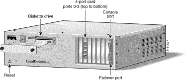
The front panel of the LocalDirector 420 is shown in Figure 2-1. Note that the diskette drive, interfaces, console port, and failover port are accessed from the front panel.
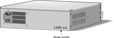
The back panel of the LocalDirector 420 is shown in Figure 2-2. The power cord receptacle and power switch are located at the back of the unit.
The LocalDirector 410 includes:
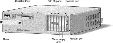
The front panel of the LocalDirector 410 is shown in Figure 2-3.
The LocalDirector 410 back panel is the same as the LocalDirector 420, shown in Figure 2-2.
Rackmount brackets are optional on the LocalDirector 420 and 410. To attach the rackmount brackets, refer to Figure 2-4.

Table 2-2 shows the interfaces that are supported on the LocalDirector platforms:
| Platform | 4-Port 10/100 Ethernet Card | 1-Port 10/100 Ethernet Card | FDDI |
|---|---|---|---|
| LocalDirector 420 | 1 included with unit, up to 4 supported
RJ-45 connectors | not supported | 2 supported
Multimode, dual-attached, SC connectors |
| LocalDirector 415 (original platform, CA-LDIR) | 1 supported
RJ-45 connectors | 2 included with unit, up to 3 supported
RJ-45 connectors | 2 supported
Multimode, dual-attached, SC connectors |
| LocalDirector 410 | not supported
RJ-45 connectors | 3 included with unit
RJ-45 connectors | not supported |
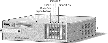
The LocalDirector interface numbering scheme has changed in version 2.1. Interfaces on LocalDirector units running version 2.1 software are numbered left to right, top to bottom. Figure 2-5 shows the interface numbering for a LocalDirector 420 with four 4-port Ethernet interface cards installed.
One 4-port Ethernet card is shipped with the LocalDirector 420, and the LocalDirector 415 will support one 4-port Ethernet card. The LocalDirector 410 does not support 4-port Ethernet cards, but it includes three single-port 10/100 Ethernet interfaces.
Each interface port has two LEDs, one amber and one green. Table 2-3 explains the states of the LEDs on the 4-Port interface cards.
| LED | LED State | Indication |
|---|---|---|
Green | off | No data transmission. |
| on | Steady data transmission. | |
| flashing | Intermittent data transmission. | |
Amber | off | Disabled or unused. If the interface was configured with the 10baseT, 100baseTX, or 100full options, the link is not up yet. |
| on | The connection is active. | |
| flashing | Autosensing. If the interface was configured with the auto option, the link is not up yet. |
The 4-port Ethernet interface card will not accept the auto option with the interface ethernet command, and will return the following error message:
ERROR: this port does not have autonegotiation capability.
The ports on the 4-port Ethernet card will default to 100BaseTX. The 10baseT|100baseTX|100full options are available, but the auto option is not.
If the peer port autonegotiates, the 4-port interface speed must be set with the10baseT or 100baseTX options; setting it to 100full will confuse the autonegotiation process on the peer port, resulting in unpredictable behavior.
The single-port card will autonegotiate, but your network interface must support auto-detection.
FDDI interface cards are optional on the LocalDirector 420 and 415, and they cannot be mixed with Ethernet interfaces.
The best way to understand FDDI is to disregard the dual-attached interfaces. Treat dual-attached interfaces like single attached interfaces; then treat FDDI like Ethernet; then the network topology problem looks like an Ethernet problem which is easier to solve. Once it is solved, put the dual-attached interfaces back into the mix by keeping in mind that the dual-attached interfaces only provide topology redundancy--if a wire is cut, you have another wire to use as a backup. It does not mean you can attach additional servers because you have extra ports.
When installed in the LocalDirector, port A is on the bottom of the interface, and port B is on the top as shown in Figure 2-6:

FDDI interface boards for the LocalDirector have dual-attached SC connectors as shown in Figure 2-7.

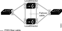
Figure 2-8 shows a LocalDirector failover implementation with FDDI interfaces:
|
|