January, 1998
This document describes changes to features and commands that are different or not described in the Cisco LocalDirector Installation and Configuration Guide (Document Number 78-3456-05).
The following sections are included:
Cisco LocalDirector version 1.6.5 includes the following changes:
- There was a bug in the configuration replication feature of LocalDirector where the enable password was not replicated to the standby unit. The enable password is now handled correctly during configuration replication. [CSCdj67564]
- Under heavy traffic loads, the LocalDirector would hang and one or both interfaces showed a state of "Line Protocol UP, Interface DOWN." [CSCdj62498]
- In version 1.6.4, if a client responded with a TCP RST/ACK when a connection was closing, the LocalDirector would reboot. [CSCdj67572]
- Previously, the no snmp-server command would remove all SNMP information from the configuration. Now you must enter the command option associated with the part of SNMP that you want to remove. For example, the no snmp-server location command will remove the text string identifying the location of an SNMP server, but not the IP address of the server. [CSCdj67573]
- When the LocalDirector was polled with a MIB browser, it would respond with "Cisco Firewall" for the sys.descrip and sys.name MIB types. It now responds correctly with
"Cisco LocalDirector." [CSCdj67574]
Version 1.6.5 software is supported on three LocalDirector platforms - the new LocalDirector 420, the new LocalDirector 410, and the original LocalDirector. The original LocalDirector (CA-LDIR) is now referred to as the LocalDirector 415. See the Cisco Product Bulletin at http://www.cisco.com/ld for more information about the LocalDirector 420 and 410.
Table 1 shows the interfaces that are supported on the LocalDirector platforms:
Table 1: Supported Interfaces by Platform
|
| 4-Port 10/100 Ethernet Card
| 1-Port 10/100 Ethernet Card
| FDDI
|
|---|
| LocalDirector 420
| 1 supported in version 1.6.5, up to 4 in version 2.x
| not supported
| 2 supported
|
LocalDirector 415
(original platform, CA-LDIR)
| 1 supported in version 2.x
| 2 supported in version 1.6.5,
3 supported in version 2.x
| 2 supported
|
| LocalDirector 410
| not supported
| 2 supported in version 1.6.5,
3 supported in version 2.x
| not supported
|
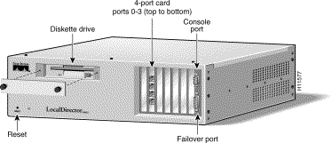
LocalDirector version 1.6.5 supports the 4-port Ethernet interface in the LocalDirector 420. The ports are numbered 0 to 3, with port 0 on the top of the interface and port 3 on the bottom. Only port 0 and port 1 are enabled at this time. The other two ports are disabled until version 2.x. It does not matter which port connects to the client network and which connects to the real server network. Multiple 4-port cards will be supported in version 2.x.
Note Ports 2 and 3 on the LocalDirector 420 are disabled until version 2.x.
The front panel of the LocalDirector 420 is shown in Figure 1. Note that the diskette drive, interfaces, console port, and failover port are accessed from the front panel.
Figure 1: LocalDirector 420 Front Panel

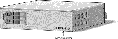
The back panel of the LocalDirector 420 is shown in Figure 2. The power cord receptacle and power switch are located at the back of the unit.
Figure 2: LocalDirector 420 and 410 Back Panel

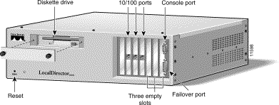
The front panel of the LocalDirector 410 is shown in Figure 3:
Figure 3: LocalDirector 410 Front Panel

The LocalDirector 410 back panel is the same as the LocalDirector 420, shown in Figure 2.
LocalDirector version 1.6.5 supports two of the 10/100 interfaces on the LocalDirector 410. The ports are numbered 0 to 2 from the left to the right, and port 2 on the third interface is disabled until version 2.x.
Note Port 2 on the third interface of the LocalDirector 410 is disabled until version 2.x.
Version 1.6.5 software is supported on the LocalDirector 415.
Note In version 1.6.5 and earlier, LocalDirector interfaces are read right to left, which is the opposite of the LocalDirector 410 and 420. In LocalDirector version 2.x, all interfaces will be numbered left to right, top to bottom. Interface numbers of existing units will change to conform to this numbering scheme.
4-port Ethernet cards are supported on the LocalDirector 420, and the LocalDirector 415 will support one 4-port Ethernet card in version 2.x. The LocalDirector 410 does not support 4-port Ethernet.
The LocalDirector interface numbering scheme will change with the introduction of 4-port Ethernet cards. The 4-port interfaces on the LocalDirector 420 are numbered left to right, top to bottom.
Interfaces on the LocalDirector 415 are numbered right to left, bottom to top. Interface numbering on existing LocalDirector 415 units will remain the same in version 1.6.x, but will change to left to right, top to bottom in version 2.x.
Note Interface numbering on the LocalDirector 415 will remain the same in version 1.6.x, but will reverse when upgraded to version 2.x. In version 2.x, all interfaces on all platforms will be read from left to right, top to bottom.
Each interface port has two LEDs, one amber and one green. Table 2 explains the states of the LEDs on the 4-Port interface cards.
- Green - Indicates data transmission activities relative to the amount of traffic.
- Flashing amber - Autosensing in progress (even with no configuration and no cable connections).
- Steady amber - Active connection (this is normal operation).
- The interface ethernet 0 auto command causes the amber LED to blink continually when the link is not up, and interface ethernet 0 [10baset|100basetx|100full] shuts off the amber LED when the link is not up.
Table 2: 4-Port Interface LEDs
| LED
| LED State
| Indication
|
|---|
Green
| off
| No data transmission.
|
| on
| Steady data transmission.
|
| flashing
| Intermittent data transmission.
|
Amber
| off
| Disabled or unused. If the interface was configured with the 10baset, 100basetx, or 100full options, the link is not up yet.
|
| on
| The connection is active.
|
| flashing
| Autosensing. If the interface was configured with the auto option, the link is not up yet.
|
Note The LED behavior on the 4-port Ethernet interface is different from other Cisco products. Use this information to determine if the LED activity indicates normal interface operation.
The 4-port card in the LocalDirector does not autonegotiate. When a 4-port interface is
configured using the int eth 1 auto command, it will perform autosense. The main difference between autosense and autonegotiation is that autosense can not be used to establish full-duplex links. Use the int eth 1 100full command to set full-duplex mode.
Note The 4-port interface will not "autosense" to full duplex. This will cause a problem if the LocalDirector interface is at half duplex and is connected to a switch on the other end trying to do full duplex.
Previously, even if no enable password was saved in flash memory, you could type anything to access privileged mode. Now, if there is no enable password, you can only press the Enter key at the password prompt. If any other text is entered, an "Invalid password" error message appears. This will prevent users from thinking that an enable password is set when it is not.
[no] delay virtual_id
The delay command is used to put connections into a "pending deletion" state instead of removing them immediately when a TCP ending sequence is received. If the delay command is set for a virtual server, the connection will remain in memory for approximately five minutes to see if any other traffic comes across for that connection.
If any data arrives for the connection, it will be put back in an "active" state. If any other packet comes across for the connection, the packet will pass through the virtual server, but the connection will not be considered active.
Use this command only when responses to and from clients are often dropped, especially during the closing of TCP connections. For example, there is a known bug with the Trumpet Winsock stack running on Windows 3.11 where HTTP get requests are sent out of order, and this causes the LocalDirector to drop the connection even though it has not completed.
- Failover is supported with a combination of LocalDirector 420, 410, and original 415 units; however, in version 2.x failover between different units will be restricted to similar configurations.
- The primary and secondary LocalDirector units in a failover configuration must be on the same IP network.
Note A failover IP address must be set for failover to work properly. Failover changed significantly in version 1.6, and failover must be re-configured when LocalDirector units are upgraded from a previous version.
- For SNMP, the interface numbers on the SNMP host are different from the interface numbers on the LocalDirector. For example:
- snmp ifc 1 = LD ifc 0
snmp ifc 2 = LD ifc 1
- The LocalDirector will not leave SynGuard mode once it is entered unless you turn SynGuard off, or raise the number of unanswered SYNs allowed above the current level (which will force it out of SynGuard mode).
- The map command will be removed in a future release of LocalDirector. The ability to define port-bound servers with the real and virtual commands has eliminated the need for the map command.
- The values assigned with the name command can be up to 32 alphanumeric characters. Names that are longer than 32 characters will be truncated. The name command is optional, and it is not related to DNS. It provides a means of making LocalDirector servers easier to configure, and the names associated to the configuration do not have to be synchronized with DNS.
- In order to use any weights defined for a real server, the weighted predictor must be set. If weights are assigned and the leastconns predictor is set, the weights will not have an affect on load balancing.
- If you are upgrading from version 1.2.5, double-check the interface and subnet mask of the LocalDirector. If these values are different from the original configuration, use the interface and ip address commands to change back to the previous settings.
- If a maximum connection value is set on all of the real servers bound to a virtual server, the virtual servers may be reported as failed. When all of the real servers have reached the value set with the maxconns command, the virtual server will not be able to service new connections. When the show virtual command is issued, it will show the state of the virtual server as FAILED, and a SYSLOG message is generated. As soon as the real servers fall below the value set by maxconns, the virtual server will automatically be brought back in-service.
- If a client initiates a Passive FTP connection, then the real server will be accessed directly for an FTP data connection. As long as routes are set up correctly on the real servers, this will not affect the FTP client; however, FTP data connections will not be counted for that real server on the LocalDirector. [CSCdj61333]
Note The only time this could be a problem is if you use unregistered IP addresses on real machines. The client cannot communicate directly with a real machine that has an unregistered IP address across the Internet.
- When communicating with LocalDirector, if a user connects to a port that is not available, the LocalDirector generates a TCP RST, which is correct. However, there was a bug in the generation of the TCP RST that caused the LocalDirector to reboot or exhibit erratic behavior.
- There was a bug in SYSLOG when two users used the show syslog command at the same time with paging turned on. The second user to continue on paged output would reboot the LocalDirector. [CSCdj53491]
- If a lot of SYSLOG messages were generated and output was directed to the console, it would cause the LocalDirector to crash.
- TCP packets generated by LocalDirector had an incorrect TCP checksum, which caused the station receiving a RST to ignore it. The LocalDirector now generates the correct checksum for RST packets.
- LocalDirector now supports fragmented packets from real servers. Fragmented packets to virtual servers have been supported since version 1.5. [CSCdj33094]
- SNMP auto discovery no longer causes LocalDirector to crash.
- The FDDI interface option was broken in version 1.6.2, but is fixed in version 1.6.3.
- The no option for the sticky command was removed in version 1.6.2, but it is included in version 1.6.3.
- The software labels on the LocalDirector interfaces were reversed, and now they are correct. The interface numbers on back of the LocalDirector match the interface numbers in the software. This will not affect use of the ping command, because the ping will be sent out of both interfaces now.
- The SNMP messages "LocalDirector booted" and "SNMP warmstart" are now sent.
- In version 1.5, SNMP/SYSLOG messages could only be sent out the interface labeled 0. In version 1.6, the SNMP/SYSLOG messages are sent out of both interfaces.
- In version 1.5, you could use Telnet to access the LocalDirector; however, you could only Telnet to the active LocalDirector and only two Telnet sessions were supported per interface. In version 1.6, you can use Telnet to access the LocalDirector from any interface or any combination of interface 0 and interface 1.
- LocalDirector correctly stores static ARPs in the configuration.
- In version 1.5, FTP control connections were timed out by the LocalDirector while the FTP data connection was still active. In version 1.6, the LocalDirector will not "timeout" an FTP control connection while the FTP data connection is still active.
- Static routes are no longer shown twice with the show route command.
- In version 1.5, broadcast packets sourced by the LocalDirector (for example, ARP requests) may have an incorrect source MAC address. In version 1.6, all broadcasts from the LocalDirector will have the correct source MAC address, which is the MAC address of the LocalDirector unit.
Cisco Connection Online (CCO) is Cisco Systems' primary, real-time support channel. Maintenance customers and partners can self-register on CCO to obtain additional information and services.
Available 24 hours a day, 7 days a week, CCO provides a wealth of standard and value-added services to Cisco's customers and business partners. CCO services include product information, product documentation, software updates, release notes, technical tips, the Bug Navigator, configuration notes, brochures, descriptions of service offerings, and download access to public and authorized files.
CCO serves a wide variety of users through two interfaces that are updated and enhanced simultaneously: a character-based version and a multimedia version that resides on the World Wide Web (WWW). The character-based CCO supports Zmodem, Kermit, Xmodem, FTP, and Internet e-mail, and it is excellent for quick access to information over lower bandwidths. The WWW version of CCO provides richly formatted documents with photographs, figures, graphics, and video, as well as hyperlinks to related information.
You can access CCO in the following ways:
- WWW: http://www.cisco.com
- WWW: http://www-europe.cisco.com
- WWW: http://www-china.cisco.com
- Telnet: cco.cisco.com
- Modem: From North America, 408 526-8070; from Europe, 33 1 64 46 40 82. Use the following terminal settings: VT100 emulation; databits: 8; parity: none; stop bits: 1; and connection rates up to 28.8 kbps.
For a copy of CCO's Frequently Asked Questions (FAQ), contact ccohelp@cisco.com. For additional information, contact ccoteam@cisco.com.
If you are a network administrator and need personal technical assistance with a Cisco product that is under warranty or covered by a maintenance contract, contact Cisco's Technical Assistance Center (TAC) at 800 553-2447, 408 526-7209, or tac@cisco.com. To obtain general information about Cisco Systems, Cisco products, or upgrades, contact 800 553-6387, 408 526-7208, or csrep@cisco.com.
Cisco documentation and additional literature are available in a CD-ROM package, which ships with your product. The Documentation CD-ROM, a member of the Cisco Connection Family, is updated monthly. Therefore, it might be more up to date than printed documentation. To order additional copies of the Documentation CD-ROM, contact your local sales representative or call customer service. The CD-ROM package is available as a single package or as an annual subscription. You can also access Cisco documentation on the World Wide Web at http://www.cisco.com, http://www-china.cisco.com, or http://www-europe.cisco.com.
If you are reading Cisco product documentation on the World Wide Web, you can submit comments electronically. Click Feedback in the toolbar, select Documentation, and click Enter the feedback form. After you complete the form, click Submit to send it to Cisco. We appreciate your comments.


