|
|

In today's world, most businesses, regardless of size, believe that access to the Internet is imperative if they are going to compete effectively. Even though the benefits of connecting to the Internet are considerable, so are the risks. When a business connects its private network to the Internet, it is not just providing its employees access to external information and Internet services; it is also providing external users with a means to access the company's own private information. Horror stories abound in the media regarding companies that have had proprietary information stolen, modified, or otherwise compromised by attackers who gained access via the Internet. For this reason, any business that has ever contemplated connecting to the Internet has been forced to deal with the issue of network security.
In response to these risks, a whole industry has formed during the last several years to meet the needs of businesses wanting to take advantage of the benefits of being connected to the Internet while still maintaining the confidentiality, integrity, and availability of their own private information and network resources. This industry revolves around firewall technology.
A firewall provides a single point of defense between two networks—it protects one network from the other. Usually, a firewall protects the company's private network from the public or shared networks to which it is connected. A firewall can be as simple as a router that filters packets or as complex as a multi-computer, multi-router solution that combines packet filtering and application-level proxy services.
Firewall technology is a young but quickly maturing industry. The first generation of firewall architectures has been around almost as long as routers, first appearing around 1985 and coming out of Cisco's IOS software division. These firewalls are called packet filter firewalls. However, the first paper describing the screening process used by packet filter firewalls did not appear until 1988, when Jeff Mogul from Digital Equipment Corporation published his studies.
During the 1989-1990 timeframe, Dave Presotto and Howard Trickey of AT&T Bell Laboratories pioneered the second generation of firewall architectures with their research in circuit relays, which are also known as circuit level firewalls. They also implemented the first working model of the third generation of firewall architectures, known as application layer firewalls. However, they neither published any papers describing this architecture nor released a product based upon their work.
As is often the case in research and development, the third generation of firewall architectures was independently researched and developed by several people across the United States during the late 1980's and early 1990's. Publications by Gene Spafford of Purdue University, Bill Cheswick of AT&T Bell Laboratories, and Marcus Ranum describing application layer firewalls first appeared during 1990 and 1991. Marcus Ranum's work received the most attention in 1991 and took the form of bastion hosts running proxy services. Ranum's work quickly evolved into the first commercial product—Digital Equipment Corporation's SEAL product.
Around 1991, Bill Cheswick and Steve Bellovin began researching dynamic packet filtering and went so far as to help develop an internal product at Bell Laboratories based upon this architecture; however, this product was never released. In 1992, Bob Braden and Annette DeSchon at USC's Information Sciences Institute began independently researching dynamic packet filter firewalls for a system that they called "Visas." Check Point Software released the first commercial product based on this fourth generation architecture in 1994.
During 1996, Scott Wiegel, Chief Scientist at Global Internet Software Group, Inc., began laying out the plans for the fifth generation firewall architecture, the Kernel Proxy architecture. Cisco Centri Firewall, released in 1997, is the first commercial product based on this architecture. While the Kernel Proxy architecture is not discussed in this chapter, it is thoroughly discussed in later chapters of this guide.
Figure 3-1 presents a time line of the major firewall architectures.

The next section describes how to establish perimeter networks, which allow you to focus your security solution at defined points within your network. The concepts presented within this section are important for planning your network so that you place your firewall server correctly within your network. Specifically, we define what it means to establish a security perimeter and the differences among trusted, untrusted, and unknown networks.
If you are familiar with the concepts and terminology used to describe security perimeters, packet filters, and proxy servers, you can skip the remainder of this chapter and proceed to the next. However, in the remaining sections of this chapter, we establish terminology and concepts important to understanding the revolutionary advancements in network security provided by Cisco Centri Firewall, as well as how to position Cisco Centri Firewall within your network.
When you define a network security policy, you must define procedures to safeguard your network and its contents and users against loss and damage. From this perspective, a network security policy plays a role in enforcing the overall security policy defined by an organization.
A network security policy focuses on controlling the network traffic and usage. It identifies a network's resources and threats, defines network use and responsibilities, and details action plans for when the security policy is violated. When you deploy a network security policy, you want it to be strategically enforced at defensible boundaries within your network. These strategic boundaries are called perimeter networks.
To establish your collection of perimeter networks, you must designate the networks of computers that you wish to protect and define the network security mechanisms that protect them. To have a successful network security perimeter, the firewall server must be the gateway for all communications between trusted networks and untrusted and unknown networks.
Each network can contain multiple perimeter networks within it. When describing how perimeter networks are positioned relative to each other, we observe three types of perimeter networks: the outermost perimeter, internal perimeters, and the innermost perimeter. Figure 3-2 depicts the relationship among the various perimeters. Note that the multiple internal perimeters are relative to a particular asset, such as the "internal perimeter that is just inside the firewall server."
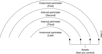
The outermost perimeter network identifies the separation point between the assets that you control and the assets that you do not control—usually, this point is the router that you use to separate your network from your Internet service provider's network. Internal perimeter networks represent additional boundaries where you have other security mechanisms in place, such as intranet firewalls and filtering routers.
Figure 3-3 depicts two perimeter networks (an outermost perimeter network and an internal perimeter network) defined by the placement of the internal and external routers and the firewall server.
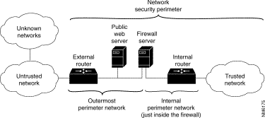
From the perspective of users on an external network, the firewall server represents all accessible computers on the trusted network. It defines the point of focus, or choke point, through which all communications between the two networks must pass.
The outermost perimeter network is the most insecure area of your network infrastructure. Normally, this area is reserved for routers, firewall servers, and public Internet servers, such as HTTP, FTP, and Gopher servers. This area of the network is the easiest area to gain access to, and therefore, it is the most frequently attacked, usually in an attempt to gain access to the internal networks. Sensitive company information that is for internal use only should not be placed on the outermost perimeter network. Following this precaution helps avoid having your sensitive information stolen or damaged.
Trusted networks are the networks inside your network security perimeter. These networks are the ones that you are trying to protect. Often, you or someone in your organization administers the computers that compose these networks, and your organization controls their security measures. Usually, trusted networks are within the security perimeter.
When you set up the firewall server, you explicitly identify the type of networks that are attached to the firewall server through network adapter cards. After the initial configuration, the trusted networks include the firewall server and all networks behind it.
One exception to this general rule is the inclusion of virtual private networks (VPNs). These networks are trusted networks that transmit data across an untrusted network infrastructure. For the purposes of our discussion, the network packets that originate on a VPN are considered to originate from within your internal perimeter network. This origin is logical because of how VPNs are established. For communications that originate on a VPN, security mechanisms must exist by which the firewall server can authenticate the origin, data integrity, and other security principles contained within the network traffic according to the same security principles enforced on your trusted networks.
Untrusted networks are the networks that are known to be outside of your security perimeter. They are untrusted because they are outside of your control. You have no control over the administration or security policies for these sites. They are the private, shared networks from which you are trying to protect your network. However, you still need and want to communicate with these networks even though they are untrusted.
When you set up the firewall server, you explicitly identify the untrusted networks from which that firewall can accept requests. Untrusted networks are outside of the security perimeter and external to the firewall server.
Unknown networks are those networks that are neither trusted nor untrusted. They are unknown quantities to the firewall because you cannot explicitly tell the firewall server that this network is a trusted or an untrusted network. Unknown networks exist outside of your security perimeter. (By default, all non-trusted networks are considered unknown networks, and the firewall applies the security policy that is applied to The Internet node in the user interface, which represents all unknown networks. However, you can identify unknown networks below The Internet node and apply more specialized policies to those untrusted networks. See Chapter 6, "Using Cisco Centri Firewall to Protect Your Network" for more information about The Internet node and the representation of networks within the Cisco Centri Firewall user interface.)
Table 3-1 summarizes the relationships among the network designations and common networks:
| Common Networks | Network Designation | Description |
|---|---|---|
Innermost Perimeter Network | Trusted | Protects innermost assets behind other perimeter networks. |
Internal Perimeter Network | Trusted and behind the firewall | A perimeter network that exists behind the firewall. |
Outermost Perimeter Network | Trusted but likely to be attacked | The perimeter network between the outermost router and the firewall server. The network area that is exposed to external networks and is most likely to be attacked because it is accessible. |
Known External Networks | Untrusted | Required access by trusted users. |
Unknown External Networks | Unknown | Not aware of their existence. |
The next section describes the evolution of technologies that have been used to provide network security in the past. Specifically, we define packet filter firewalls, circuit level firewalls, application layer firewalls, and dynamic packet filter firewalls—four common architectures for building firewalls—and explain the advantages and disadvantages of these four architectures.
Most firewall technologies provide different capabilities for auditing communication events. Usually, the firewalls generate audit records detailing the cause and circumstances surrounding the triggering of audit events. As firewall technology improves, firewalls inspect additional network packet information, use more sophisticated inspection algorithms, maintain more state information, and inspect the network packets at more network layers. As such, more mature firewall technology provides more detailed audit records, or summary information, about the network packets that are allowed through or prevented from traversing the firewall. By analyzing such audit records, administrators can often detect network security policy problems, such as attempts to break in or misconfiguration of the firewall's network security policy enforcement features. As a general rule, more detailed and descriptive audit record information yields better monitoring capabilities in a firewall product.
Before Cisco Centri Firewall, firewalls inspected network traffic using one of four architectural models, which are defined by the information that they examine to make security-relevant decisions. In the next four sections, we define these different architectures in detail.
Packet filters typically enable you to manipulate (that is, permit or prohibit) the transfer of data based on the following controls:
Figure 3-4 depicts the network packet evaluation process used by a packet filter firewall.
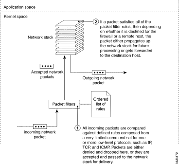
Packet filters generally do not understand the application layer protocols used in the communication packets. Instead, they work by applying a rule set that is maintained in the TCP/IP kernel. This rule set contains an associated action that will be applied to any packets matching the criteria mentioned above.
The action taken may take on one of two values: "deny" or "permit" the network packet. Two lists, the deny list and the permit list, are maintained in the kernel. For a network packet to be routed to its proper destination, it must first pass a check of both the deny and permit lists. That is, it must not be expressly denied, and it must be expressly permitted. Some packet filters that are incorporated into router hardware implement a different policy. In these types of packet filters, the packet must be expressly denied or else it is permitted. In order for you to understand the filtering rules, you must consider the security stance utilized by the routing hardware.
Packet filters typically implement command sets that allow the checking of the source and destination port numbers on the TCP and UDP transport layer protocols. This check determines whether an applicable permit or deny rule exists for that specific port and protocol combination. Due to the fact that the ICMP protocol layer does not utilize port numbers for its communications protocol, it is difficult for packet filters to apply any security policy to this form of network traffic. In order to apply an effective security policy to ICMP, the packet filter must maintain state tables to ensure that an ICMP reply message was recently requested from an internal host. This ability to track communications state is one of the primary differences between simple packet filters and dynamic packet filters.
Because packet filters are implemented in the network layer, they generally do not understand how to process state information in the high-level protocols, such as FTP. The more sophisticated packet filters are able to detect IP, TCP, UDP, and ICMP. Using a packet filter that includes the TCP/UDP port filtering capability, you can permit certain types of connections to be made to specific computers while prohibiting other types of connections to those computers and similar connections to other computers.
The complete network packet inspection adheres to the following general algorithm:
Because this type of firewall does not inspect the network packet's application layer data and does not track the state of connections, this solution is the least secure of the firewall technologies. It allows access through the firewall with a minimal amount of scrutiny. In other words, if the checks succeed, the network packet is allowed to be routed through the firewall as defined by the rules in the firewall's routing table. However, because it does less processing than the other technologies, it is the fastest firewall technology available and is often implemented in hardware solutions, such as IP routers.
Packet filter firewalls often readdress network packets so that outgoing traffic appears to have originated from a different host rather than an internal host. The process of readdressing network packets is called network address translation. Network address translation hides the topology and addressing schemes of trusted networks from untrusted networks.
To summarize, firewalls based on the packet filtering technologies have the following advantages:
Firewalls based on the packet filtering technologies have the following disadvantages:
A circuit level firewall is a second-generation firewall technology that validates the fact that a packet is either a connection request or a data packet belonging to a connection, or virtual circuit, between two peer transport layers.
To validate a session, a circuit level firewall examines each connection setup to ensure that it follows a legitimate handshake for the transport layer protocol being used (the only widely used transport protocol that uses a handshake is TCP). In addition, data packets are not forwarded until the handshake is complete. The firewall maintains a table of valid connections (which includes complete session state and sequencing information) and lets network packets containing data pass through when network packet information matches an entry in the virtual circuit table. Once a connection is terminated, its table entry is removed, and that virtual circuit between the two peer transport layers is closed.
Figure 3-5 depicts the network packet evaluation process used by a circuit level firewall.
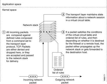
When a connection is set up, the circuit level firewall typically stores the following information about the connection:
Using this information, the circuit level firewall checks the header information contained within each network packet to determine whether the transmitting computer has permission to send data to the receiving computer and whether the receiving computer has permission to receive that data.
Circuit level firewalls have only limited understanding of the protocols used in the network packets. They can only detect one transport layer protocol, TCP. Like packet filters, circuit level firewalls work by applying a rule set that is maintained in the TCP/IP kernel.
Circuit level firewalls allow access through the firewall with a minimal amount of scrutiny by building a limited form of connection state. Only those network packets that are associated with an existing connection are allowed through the firewall. When a connection establishment packet is received, the circuit level firewall checks its rule bases to determine whether that connection should be allowed. If the connection is allowed, all network packets associated with that connection are routed through the firewall as defined in the firewall server's routing table with no further security checks. This method is very fast and provides a limited amount of state checking.
Circuit level firewalls can perform additional checks to ensure that a network packet has not been spoofed and that the data contained within the transport protocol header complies with the definition for that protocol, which allows the firewall to detect limited forms of modified packet data.
Circuit level firewalls often readdress network packets so that outgoing traffic appears to have originated from the firewall rather than an internal host. As stated previously, this process of readdressing network packets is called network address translation, and because circuit level firewalls maintain information about each session, they can properly map external responses back to the appropriate internal host.
To summarize, circuit level firewalls have the following advantages:
Circuit level firewalls have the following disadvantages:
Most application layer firewalls include specialized application software and proxy services. Proxy services are special-purpose programs that manage traffic through a firewall for a specific service, such as HTTP or FTP. Proxy services are specific to the protocol that they are designed to forward, and they can provide increased access control, careful detailed checks for valid data, and generate audit records about the traffic that they transfer.
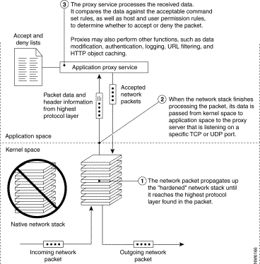
Figure 3-6 depicts the network packet evaluation process used by a application layer firewall.
Each application proxy requires two components that are typically implemented as a single executable: a proxy server and a proxy client. A proxy server acts as the end server for all connection requests originated on a trusted network by a real client. That is, all communication between internal users and the Internet passes through the proxy server rather than allowing users to communicate directly with other servers on the Internet. An internal user, or client, sends a request to the proxy server for connecting to an external service, such as FTP or Telnet. The proxy server evaluates the request and decides to permit or deny the request based on a set of rules that are managed for the individual network service. Proxy servers understand the protocol of the service that they are evaluating, and therefore, they only allow those packets through that comply with the protocol definitions. They also enable additional benefits, such as detailed audit records of session information, user authentication, and caching.
Figure 3-7 depicts the flow of communications between a real client and a network server when the communications pass through a proxy service.
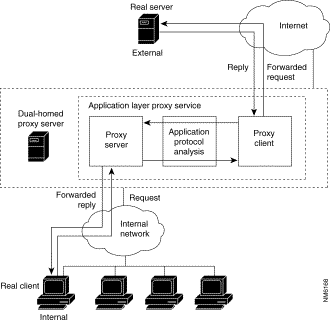
Proxy services never allow direct connections, and they force all network packets to be examined and filtered for suitability. Instead of communicating directly with the real service, a user communicates to the proxy server (because the user's default gateway is set to point to the proxy server on the firewall). The same is true from the perspective of the real service communicating with a user. The proxies handle all communications between the user and a real service.
A proxy service sits transparently between a user on the internal network and the real service on the external network. That is, from the user's perspective, that user is dealing directly with the real service. From the real service's perspective, it is dealing directly with a user on the proxy server (instead of the user's real computer).
Proxy services are implemented on top of the firewall host's network stack and operate only in the application space of the operating system. Consequently, each packet must pass through the low-level protocols in the kernel before being passed up the stack to application space for a thorough inspection of the packet headers and packet data by the proxies. Then, the packet must travel back down to the kernel, and then back down the stack for distribution. Because each packet in a session is subject to this process, proxy services are notoriously slow.
Like circuit level firewalls, application layer firewalls can perform additional checks to ensure that a network packet has not been spoofed, and they often perform network address translation.
To summarize, proxy services have several key advantages:
Proxy services also have some disadvantages. These disadvantages include the following:
This firewall accomplishes its functional requirements by associating all UDP packets that cross the security perimeter with a virtual connection. If a response packet is generated and sent back to the original requester, then a virtual connection is established and the packet is allowed to traverse the firewall server. The information associated with a virtual connection is typically remembered for a short period of time, and if no response packet is received within this time period, the virtual connection is invalidated.
Figure 3-8 depicts the network packet evaluation process used by a dynamic packet filter firewall.
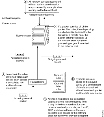
This feature is useful for allowing application layer protocols, such as the Domain Name System (DNS), to operate across your security perimeter. An internal DNS server must originate requests to other DNS servers running on the Internet to retrieve address information for unknown hosts. DNS servers may make these requests using a TCP connection or UDP virtual connection.
A dynamic packet filter firewall may also be used to provide support for a limited subset of the ICMP transport protocol. ICMP is often used to test network connectivity by sending a pair of network packets between two cooperating hosts. Because the firewall server can allow a response to cross the firewall at the request of an internal host, the internal host is able to deduce that a host exists on an untrusted network.
When considering alternative firewall technologies, a common question is "what are the trade-offs between performance and security?" To answer to this question, we must consider how far up the network stack a network packet must travel, as well as what level of security checks are being performed on each packet. Packet filter firewalls generally provide the highest performance, followed by circuit level firewalls, dynamic packet filter firewalls, and application layer firewalls.
The level of security checks generally follows the reverse pattern because as network packets pass through more protocol layers, they are inspected in more detail. As a result, application layer firewalls are considered more secure than dynamic packet filter firewalls, which are considered more secure than circuit level firewalls, etc. However, because a circuit level firewall does not perform extensive security checks, other than whether a network packet is associated with a valid connection, it can (and often does) perform faster than a packet filter firewall that contains a large set of accept and deny rules.
In general, application layer firewalls are the slowest architecture due to the fact that all network packets are sent up one network stack and down a different one, thus being treated as two separate network sessions. Application layer firewalls also implement the broadest set of security data checks, which increases the processing time required. Throughout the industry, application layer firewalls are generally considered to provide the best security.
When routers were first developed, the operating systems used to program them had command line interfaces. Because of this interface, administrators were forced to learn programming languages that instructed the routers as to how they should operate. These programming languages were and still are cryptic and difficult to use. The following example presents the rules used to program a router to allow traffic across it for an FTP server that resides at 192.168.1.2:
recv/syn/dstport=ftp/dstaddr=192.168.1.2
!recv/syn/dstport=ftp
syn/dstport=1024-65535
Because packet filters performed functions very similar to routers, these router-based languages transitioned into the first generation packet filters. These languages require that each protected network object have an individual rule associated with it for each network service that the object can access. A network object is any addressable entity on the network. As such, it can be a computer, a network printer, a subnet, or a router.
Eventually, when proxy services, and later dynamic packet filters and circuit level firewalls, appeared on the scene, they were developed using similar router-based rule sets. Because of the introduction of additional features and options, the programming languages grew more complicated and became network-service specific. Today this "router-based rule set" method of defining security policies is universal in the industry.
The following example is the set of rules required to provide the hosts, 192.168.1.*, with access to FTP:
ftp-gw: denial-msg /usr/local/etc/ftp-deny.txt

ftp-gw: welcome-msg /usr/local/etc/ftp-welcome.txt

ftp-gw: help-msg /usr/local/etc/ftp-help.txt

ftp-gw: timeout 7200

ftp-gw: permit-hosts 192.168.1.* -log { retr stor }
The exploding demand for Internet and intranet connectivity far exceeds the supply of available security experts who are familiar with router-based rule sets or with command line operating systems. The long lists of security policy rules are often difficult to manage no matter what the level of expertise of the administrator. Also, it is extremely difficult to ensure that all of the objects on a network are protected without spending a great deal of time evaluating the lists of rules.
Some firewall vendors have responded to this problem by providing icons. These icons represent rule types that are intended to make the command line policy lists more user friendly. The addition of icons, however, has not reduced the complexity of ensuring that each network object is protected, and the user interfaces based on this scheme still require individual rules for each network service to be accessed by a network object. As a result, administrators are still required to use "machine language" when defining rules that enforce their security policies.
The next chapter completes our discussions of requisite background information by defining network security policies and the role that they play within the Cisco Centri Firewall. It also introduces several features within the Cisco Centri Firewall user interface.
![]()
![]()
![]()
![]()
![]()
![]()
![]()
![]()
Posted: Sat Sep 28 22:56:24 PDT 2002
All contents are Copyright © 1992--2002 Cisco Systems, Inc. All rights reserved.
Important Notices and Privacy Statement.