|
|

Table Of Contents
Installation Note for the Cisco CWDM Passive
Optical SystemInstalling the CWDM Passive Optical System
Installing the CWDM OADM and Multiplexer/Demultiplexer Modules
Removing the CWDM OADM or Multiplexer/Demultiplexer Module
Installing, Removing, and Maintaining CWDM GBICs
Connecting the CWDM Passive Optical System to Your System
Obtaining Technical Assistance
Obtaining Additional Publications and Information
Installation Note for the Cisco CWDM Passive
Optical System
Product Numbers: CWDM-MUX-AD-1470=, CWDM-MUX-AD-1490=, CWDM-MUX-AD-1510=, CWDM-MUX-AD-1530=, CWDM-MUX-AD-1550=, CWDM-MUX-AD-1570=, CWDM-MUX-AD-1590=, CWDM-MUX-AD-1610=, CWDM-MUX-4=, CWDM-MUX-8=, CWDM-MUX-4-SF1=, CWDM-MUX-4-SF2=, CWDM-CHASSIS-2=
This installation note provides the technical specifications and installation instructions for the Cisco Coarse Wave Division Multiplexer (CWDM) passive optical system.
Contents
This installation note contains the following sections:
•
Overview
•
•
•
Overview
The Cisco CWDM passive optical system provides optical networking support for high-speed data communication for metropolitan area networks (MANs) over a grid of eight CWDM optical wavelengths in both ring or point-to-point configurations.
The Cisco CWDM passive optical system includes the following components:
•
•
–
–
–
–
•
CWDM 2-Slot Chassis
The CWDM 2-slot chassis (CWDM-CHASSIS-2) is a standard 19-inch chassis that is one rack unit (RU) in height. Each CWDM 2-slot chassis can hold two CWDM OADM modules. You can install the CWDM 2-slot chassis in the same equipment rack as your system or in an adjacent rack so that you can connect the OADMs to the CWDM GBICs.
CWDM OADMs
The CWDM OADMs are passive devices that can multiplex/demultiplex or add/drop wavelengths from multiple fibers onto one optical fiber. The OADM connectors are interfaced to the color-matching CWDM GBICs on the equipment side. All the modules are the same size. The CWDM 2-slot chassis allows you to rack mount up to two CWDM OADMs in a single rack unit. There are four different types of CWDM OADMs:
•
•
•
•
See Table 2 for a comparison of the CWDM passive device types.
Figure 1 shows the front panel of the CWDM 4-channel OADM module. Figure 2 shows the CWDM 8-channel multiplexer/demultiplexer module. Figures 3 through 10 show the dual single-channel OADM modules for each of the available wavelengths.
The OADM module ports are color coded to help with installation. Each color indicates the wavelength of the port. For more information about the color codes, see the "Connecting the CWDM Passive Optical System to Your System" section. Figure 11 and Figure 12 show the front panels of the CWDM 4-channel multiplexer/demultiplexer modules (CWDM-MUX-4-SF1 and CWDM-MUX-4-SF2).
Figure 1 4-Channel OADM (CWDM-MUX-4) Front Panel
Figure 2 8-Channel Multiplexer/Demultiplexer (CWDM-MUX-8) Front Panel
Figure 3 Dual Single-Channel OADM Front Panel (1470 nm)
Figure 4 Dual Single-Channel OADM Front Panel (1490 nm)
Figure 5 Dual Single-Channel OADM Front Panel (1510 nm)
Figure 6 Dual Single-Channel OADM Front Panel (1530 nm)
Figure 7 Dual Single-Channel OADM Front Panel (1550 nm)
Figure 8 Dual Single-Channel OADM Front Panel (1570 nm)
Figure 9 Dual Single-Channel OADM Front Panel (1590 nm)
Figure 10 Dual Single-Channel OADM Front Panel (1610 nm)
Figure 11 Single-Fiber 4-Channel Multiplexer/Demultiplexer (CWDM-MUX-4-SF1) Front Panel
Figure 12 Single-Fiber 4-Channel Multiplexer/Demultiplexer (CWDM-MUX-4-SF2) Front Panel
CWDM GBICs
A CWDM GBIC is a hot-swappable input/output device that links your switching module to the CWDM passive optical system using a pair of single-mode fiber-optic cables. You can connect your multiplexed/demultiplexed wavelengths and added/dropped channels to CWDM GBICs that are installed in your system.
CWDM GBICs are available in eight wavelengths (see Table 3.) Each GBIC is color coded to match the connector colors on the OADM modules.
For information on installing, removing, and maintaining the CWDM GBICs, refer to the CWDM GBIC Installation Note that accompanies the CWDM GBICs.
Safety Overview
Throughout this publication, safety warnings appear in procedures that, if performed incorrectly, can harm you. A warning symbol precedes each warning statement.
Warning Definition
Warning
Warning
Hardware Requirements
Use single-mode fiber-optic cable with SC connectors to connect the CWDM passive optical system to your system.
Required Tools
You will need these tools to install the CWDM passive optical system:
•
•
•
Installing the CWDM Passive Optical System
The following sections provide the installation procedures for the components:
•
•
•
•
•
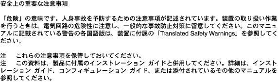
Installing the 2-Slot Chassis
Note
Caution
To mount the 2-slot chassis in an equipment rack, follow these steps:
Step 1
Step 2
Step 3
Figure 13 Mounting the 2-Slot Chassis in the Rack
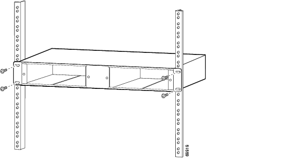
Installing the CWDM OADM and Multiplexer/Demultiplexer Modules
Caution
To install the CWDM OADM or multiplexer/demultiplexer modules, follow these steps:
Step 1
Step 2
Figure 14 Installing a CWDM OADM or Multiplexer/Demultiplexer Module
Step 3
Step 4
Removing the CWDM OADM or Multiplexer/Demultiplexer Module
Caution
To remove the CWDM OADM module or the multiplexer/demultiplexer module, follow these steps:
Step 1
Step 2
Step 3
Step 4
Installing, Removing, and Maintaining CWDM GBICs
For information on installing, removing, and maintaining the CWDM GBICs, refer to the CWDM GBIC Installation Note that accompanies the CWDM GBICs.
Connecting the CWDM Passive Optical System to Your System
Use the CWDM passive optical system connector color codes shown in Table 4 to help you connect the CWDM passive optical system to your system.
See Figure 1 through Figure 12 for the OADM and multiplexer/demultiplexer module front panels.
Warning
Connecting Cables to the Dual Single-Channel OADM Module
Note
To connect the cables to the dual single-channel OADM module, follow these steps (see Figure 15):
Step 1
Note
Warning
Note
Step 2
Note
Step 3
Step 4
Figure 15 Cabling a CWDM Dual Single-Channel OADM Module
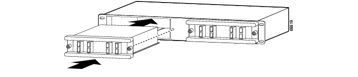
Connecting Cables to the CWDM 4-Channel OADM Module
Note
To connect the cables to the CWDM 4-channel OADM module, follow these steps (see Figure 16):
Step 1
Note
Warning
Note
Step 2
Note
Step 3
Figure 16 Cabling a 4-Channel OADM Module
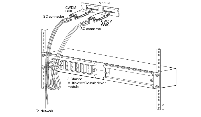
Connecting Cables to the CWDM 8-Channel Multiplexer/Demultiplexer Module
Note
To connect cables to a CWDM 8-channel multiplexer/demultiplexer module, follow these steps (see Figure 17):
Step 1
Note
Note
Warning
Step 2
Note
Step 3
Figure 17 Cabling a CWDM 8-Channel Multiplexer/Demultiplexer Module
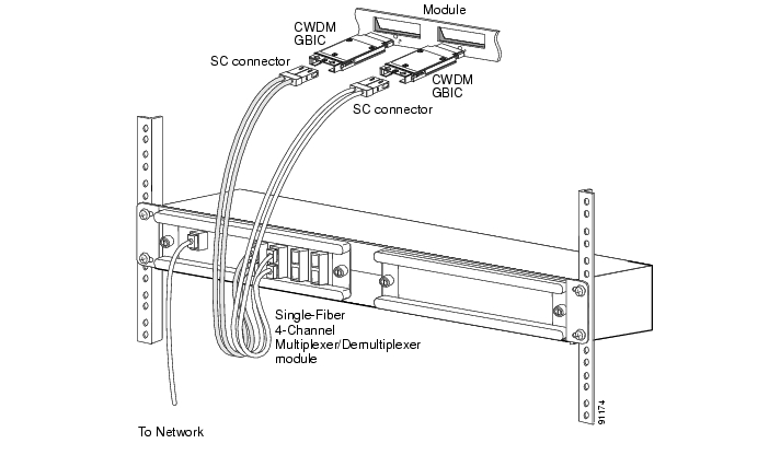
Connecting Cables to the Single-Fiber 4-Channel Multiplexer/Demultiplexer Module
Note
To connect the cables to the single-fiber 4-channel multiplexer/demultiplexer module, follow these steps (see Figure 16):
Step 1
Note
Warning
Note
Step 2
Note
Step 3
Figure 18 Cabling a Single-Fiber 4-Channel Multiplexer/Demultiplexer Module (CWDM-MUX-4-SF1/2)
Specifications
Table 5 lists the environmental specifications for the CWDM OADM and multiplexer/demultiplexer modules. Table 6 lists the optical specifications for the CWDM OADM and multiplexer/demultiplexer modules.
Translated Safety Warnings
This section contains the translations to the warnings that appear in this publication.
Installation Warning
Product Disposal Warning
Class 1M Laser Caution
Unterminated Fiber Warning
Obtaining Documentation
Cisco provides several ways to obtain documentation, technical assistance, and other technical resources. These sections explain how to obtain technical information from Cisco Systems.
Cisco.com
You can access the most current Cisco documentation on the World Wide Web at this URL:
http://www.cisco.com/univercd/home/home.htm
You can access the Cisco website at this URL:
International Cisco web sites can be accessed from this URL:
http://www.cisco.com/public/countries_languages.shtml
Documentation CD-ROM
Cisco documentation and additional literature are available in a Cisco Documentation CD-ROM package, which may have shipped with your product. The Documentation CD-ROM is updated monthly and may be more current than printed documentation. The CD-ROM package is available as a single unit or through an annual subscription.
Registered Cisco.com users can order the Documentation CD-ROM (product number DOC-CONDOCCD=) through the online Subscription Store:
http://www.cisco.com/go/subscription
Ordering Documentation
You can find instructions for ordering documentation at this URL:
http://www.cisco.com/univercd/cc/td/doc/es_inpck/pdi.htm
You can order Cisco documentation in these ways:
•
http://www.cisco.com/en/US/partner/ordering/index.shtml
•
http://www.cisco.com/go/subscription
•
Documentation Feedback
You can submit comments electronically on Cisco.com. On the Cisco Documentation home page, click Feedback at the top of the page.
You can e-mail your comments to bug-doc@cisco.com.
You can submit your comments by mail by using the response card behind the front cover of your document or by writing to the following address:
Cisco Systems
Attn: Customer Document Ordering
170 West Tasman Drive
San Jose, CA 95134-9883We appreciate your comments.
Obtaining Technical Assistance
Cisco provides Cisco.com, which includes the Cisco Technical Assistance Center (TAC) Website, as a starting point for all technical assistance. Customers and partners can obtain online documentation, troubleshooting tips, and sample configurations from the Cisco TAC website. Cisco.com registered users have complete access to the technical support resources on the Cisco TAC website, including TAC tools and utilities.
Cisco.com
Cisco.com offers a suite of interactive, networked services that let you access Cisco information, networking solutions, services, programs, and resources at any time, from anywhere in the world.
Cisco.com provides a broad range of features and services to help you with these tasks:
•
•
•
•
•
To obtain customized information and service, you can self-register on Cisco.com at this URL:
Technical Assistance Center
The Cisco TAC is available to all customers who need technical assistance with a Cisco product, technology, or solution. Two levels of support are available: the Cisco TAC website and the Cisco TAC Escalation Center. The avenue of support that you choose depends on the priority of the problem and the conditions stated in service contracts, when applicable.
We categorize Cisco TAC inquiries according to urgency:
•
•
•
•
Cisco TAC Website
You can use the Cisco TAC website to resolve P3 and P4 issues yourself, saving both cost and time. The site provides around-the-clock access to online tools, knowledge bases, and software. To access the Cisco TAC website, go to this URL:
All customers, partners, and resellers who have a valid Cisco service contract have complete access to the technical support resources on the Cisco TAC website. Some services on the Cisco TAC website require a Cisco.com login ID and password. If you have a valid service contract but do not have a login ID or password, go to this URL to register:
http://tools.cisco.com/RPF/register/register.do
If you are a Cisco.com registered user, and you cannot resolve your technical issues by using the Cisco TAC website, you can open a case online at this URL:
http://www.cisco.com/en/US/support/index.html
If you have Internet access, we recommend that you open P3 and P4 cases through the Cisco TAC website so that you can describe the situation in your own words and attach any necessary files.
Cisco TAC Escalation Center
The Cisco TAC Escalation Center addresses priority level 1 or priority level 2 issues. These classifications are assigned when severe network degradation significantly impacts business operations. When you contact the TAC Escalation Center with a P1 or P2 problem, a Cisco TAC engineer automatically opens a case.
To obtain a directory of toll-free Cisco TAC telephone numbers for your country, go to this URL:
http://www.cisco.com/warp/public/687/Directory/DirTAC.shtml
Before calling, please check with your network operations center to determine the level of Cisco support services to which your company is entitled: for example, SMARTnet, SMARTnet Onsite, or Network Supported Accounts (NSA). When you call the center, please have available your service agreement number and your product serial number.
Obtaining Additional Publications and Information
Information about Cisco products, technologies, and network solutions is available from various online and printed sources.
•
http://www.cisco.com/en/US/products/products_catalog_links_launch.html
•
•
http://www.cisco.com/en/US/about/ac123/ac114/about_cisco_packet_magazine.html
•
http://business.cisco.com/prod/tree.taf%3fasset_id=44699&public_view=true&kbns=1.html
•
http://www.cisco.com/en/US/about/ac123/ac147/about_cisco_the_internet_protocol_journal.html
•
http://www.cisco.com/en/US/learning/le31/learning_recommended_training_list.html

![]()
![]()
![]()
![]()
![]()
![]()
![]()
![]()
Posted: Thu Sep 23 11:09:21 PDT 2004
All contents are Copyright © 1992--2004 Cisco Systems, Inc. All rights reserved.
Important Notices and Privacy Statement.