|
|

Table Of Contents
Configuring Virtual Connections
Characteristics and Types and of Virtual Connections
Configuring Permanent Virtual Channel Connections
Configuring Terminating PVC Connections
Configuring Permanent Virtual Path Connections
Configuring Soft PVC Connections
Guidelines for Creating Soft PVCs
Configuring Soft Permanent Virtual Channels
Configuring Soft PVP Connections
Configuring Non-Default Well-Known PVCs
Overview of Non-Default PVC Configuration
Configuring Virtual Connections
This chapter describes how to configure virtual connections (VCs) in a typical ATM network after autoconfiguration has established the default network connections. The network configuration modifications described in this chapter are used to optimize your ATM network operation.
Characteristics and Types and of Virtual Connections
The characteristics of the VC, established when the VC is created, include:
•
Quality of service (QoS)
•
•
•
These switching features can be turned off with interface configuration commands; autonomous switching must be explicitly enabled per interface. SVC connection setup is possible both on trunk/subtended interfaces as well as all subscriber ports.
The total number of SVCs supported is approximately 24k. The total number of PVCs supported is approximately 5k (constrained by Flash size). The call rate is two hundred calls per second.
Table 5-1 lists the types of supported virtual connections.
Configuring Permanent Virtual Channel Connections
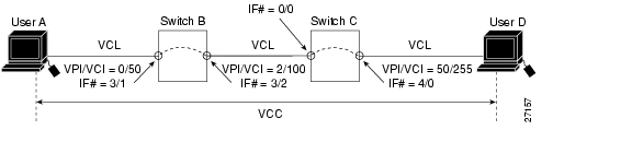
This section describes how to configure DSLAM VCCs. A VCC is established as a bidirectional facility to transfer ATM traffic between two ATM layer users. Figure 5-1 shows an example VCC between ATM user A and user D.
Figure 5-1 Virtual Channel Connection Example
Note
To configure a point-to-point VCC, perform these steps, beginning in global configuration mode:
1.
interface atm slot/port[.sub-inter#]
Select the interface to be configured.
2.
atm pvc vpi [vci | any-vci1 ] [upc upc] [pd pd2 ] [rx-cttr index] [tx-cttr index] interface atmslot/port[.vpt#] vpi [vci | any-vci] [upc upc]
Configure the PVC.
1 The any-vci parameter is only available for ATM interface0/0.
2 The parameter pd is not applicable to a virtual path.
Note
Note
Examples
This example shows how to configure the internal cross-connect PVC on DSLAM B between interface 0/1, VPI = 0, VCI = 50 and interface 0/2, VPI = 2, VCI = 100 (see Figure 5-1):
DSLAM-B(config)# interface atm 0/1DSLAM-B(config-if)# atm pvc 0 50 interface atm 0/2 2 100This example shows how to configure the internal cross-connect PVC on DSLAM C between interface 1/0, VPI = 2, VCI = 100 and interface0/1, VPI 50, VCI = 255:
DSLAM-C(config)# interface atm 1/0DSLAM-C(config-if)# atm pvc 2 100 interface atm 0/1 50 255Each subsequent VC cross-connection and link must be configured until the VC is terminated to create the entire VCC.
This example shows how to configure the CPU leg of any terminating PVC:
DSLAM(config)# interface atm0/0DSLAM(config-if)# atm pvc 0 ?<32-16383> vciany-vci Choose any available vciDSLAM(config-if)# atm pvc 0 any-vciDSLAM(config-if)#When configuring the CPU leg of a PVC that is not a tunnel, the VPI should be configured as 0. The preferred method of VCI configuration is to select the any-vci parameter, unless a specific VCI is needed as a parameter in another command, such as map-list.
Note
To show the VC configuration, use these EXEC commands:
1.
show atm interface [atm slot/port]
Show the ATM interface configuration.
2.
show atm vc [interface atm slot/port vpi vci]
Show the PVC interface configuration.
Examples
This example displays the DSLAM B PVC configuration on ATM interface 0/2:
DSLAM-B# show atm interface 0/2Interface: ATM0/2 Port-type: suni-dualIF Status: UP Admin Status: upAuto-config: enabled AutoCfgState: completedIF-Side: Network IF-type: NNIUni-type: not applicable Uni-version: not applicableMax-VPI-bits: 8 Max-VCI-bits: 14Max-VP: 255 Max-VC: 16383Svc Upc Intent: pass Signalling: EnabledATM Address for Soft VC: 47.0091.8100.0000.0001.0000.0001.4000.0c81.8010.00Configured virtual links:PVCLs SoftVCLs SVCLs PVPLs SoftVPLs SVPLs Total-Cfgd Installed-Conns5 0 0 0 0 0 5 5Logical ports(VP-tunnels): 0Input cells: 527452 Output cells: 5274855 minute input rate: 0 bits/sec, 0 cells/sec5 minute output rate: 0 bits/sec, 0 cells/secInput AAL5 pkts: 344372, Output AAL5 pkts: 344384, AAL5 crc errors: 0This example displays the DSLAM B PVC configuration on ATM interface 0/2:
DSLAM-B# show atm vc interface atm 0/2Interface VPI VCI Type X-Interface X-VPI X-VCI Encap StatusATM0/2 0 5 PVC ATM0/0 0 57 QSAAL UPATM0/2 0 16 PVC ATM0/0 0 37 ILMI UPATM0/2 0 18 PVC ATM0/0 0 73 PNNI UPATM0/2 0 50 PVC ATM0/0 2 100 UPATM0/2 1 50 PVC ATM0/0 0 80 SNAP UPThis example displays the DSLAM B configuration on interface 0/1, VPI = 0, VCI = 50:
DSLAM-B# show atm vc interface atm 0/1 0 50Interface: ATM0/1, Type: suni-dualVPI = 0 VCI = 50Status: UPTime-since-last-status-change: 00:31:30Connection-type: PVCCast-type: point-to-pointPacket-discard-option: disabledUsage-Parameter-Control (UPC): passNumber of OAM-configured connections: 0OAM-configuration: disabledOAM-states: Not-applicableCross-connect-interface: ATM0/2, Type: suni-dualCross-connect-VPI = 2Cross-connect-VCI = 100Cross-connect-UPC: passCross-connect OAM-configuration: disabledCross-connect OAM-state: Not-applicableRx cells: 0, Tx cells: 0Rx connection-traffic-table-index: 1Rx service-category: UBR (Unspecified Bit Rate)Rx pcr-clp01: 7113539Rx scr-clp01: noneRx mcr-clp01: noneRx cdvt: 1024 (from default for interface)Rx mbs: noneTx connection-traffic-table-index: 1Tx service-category: UBR (Unspecified Bit Rate)Tx pcr-clp01: 7113539Tx scr-clp01: noneTx mcr-clp01: noneTx cdvt: noneTx mbs: noneThis example displays the DSLAM B PVC configuration on ATM interface 0/2, VPI = 0, VCI = 50:
DSLAM-B# show atm vc interface atm 0/2 0 50Interface: ATM0/2, Type: suni-dualVPI = 0 VCI = 50Status: UPTime-since-last-status-change: 4d02hConnection-type: PVCCast-type: point-to-pointPacket-discard-option: disabledUsage-Parameter-Control (UPC): passWrr weight: 32Number of OAM-configured connections: 0OAM-configuration: disabledOAM-states: Not-applicableCross-connect-interface: ATM0/1, Type: suni-dualCross-connect-VPI = 2Cross-connect-VCI = 100Cross-connect-UPC: passCross-connect OAM-configuration: disabledCross-connect OAM-state: Not-applicableThreshold Group: 5, Cells queued: 0Rx cells: 0, Tx cells: 0Tx Clp0:0, Tx Clp1: 0Rx Clp0:0, Rx Clp1: 0Rx Upc Violations:0, Rx cell drops:0Rx Clp0 q full drops:0, Rx Clp1 qthresh drops:0Rx connection-traffic-table-index: 1Rx service-category: UBR (Unspecified Bit Rate)Rx pcr-clp01: 7113539Rx scr-clp01: noneRx mcr-clp01: noneRx cdvt: 1024 (from default for interface)Rx mbs: noneTx connection-traffic-table-index: 1Tx service-category: UBR (Unspecified Bit Rate)Tx pcr-clp01: 7113539Tx scr-clp01: noneTx mcr-clp01: noneTx cdvt: noneTx mbs: noneConfiguring Terminating PVC Connections
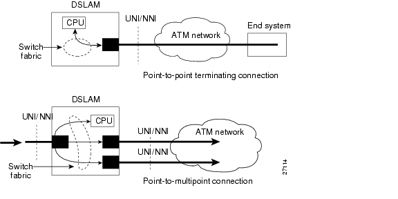
This section describes how to configure point-to-point terminating PVC connections. Terminating connections provide the connection to the DSLAM CPU for control channels for Interim Local Management Interface (ILMI), signaling, and Private Network-to-Network Interface (PNNI) plus network management.
Figure 5-2 shows an example of transit and terminating connections.
Figure 5-2 Virtual Connection Types Example
Point-to-point is a type of terminating connection. Terminating connections are configured using the same commands as transit connections (discussed in the previous sections). However, all switch terminating connections use interface 0/0 to connect to the switch CPU.
To configure point-to-point terminating PVC connections, perform these steps, beginning in global configuration mode:
1.
interface atm slot-A/port-A[.vpt#]
Select the interface to be configured.
2.
atm pvc vpi-A [vci-A | any-vci1 ] [cast-type p2mp-leaf p2mp-root p2p] [upc upc-A] [pd pd] [rx-cttr index] [tx-cttr index] interface atm slot-B/subslot-B/port-B[.vpt#] vpi-B [vci-A | any-vci] [upc upc-B] [cast-type p2mp-leaf | p2mp-root | p2p]
Configure the PVC between ATM switch connections.
1 The any-vci feature is only available for interface ATM 0/0.
Note
Examples
This example shows how to configure the CPU leg of any terminating PVC:
DSLAM(config)# interface atm0/0DSLAM(config-if)# atm pvc 0 ?<32-16383> vciany-vci Choose any available vciDSLAM(config-if)# atm pvc 0 any-vciWhen configuring the CPU leg of a PVC that is not a tunnel, the VPI should be configured as 0. The preferred method of VCI configuration is to select the any-vci parameter, unless a specific VCI is needed as a parameter in another command, such as map-list.
Note
This example shows how to configure the internal cross-connect PVC between interface 0/2, VPI = 1, VCI = 50 and the terminating connection at the CPU interface 0/0, VPI = 0, and VCI unspecified:
DSLAM-B(config)# interface atm 0/2DSLAM-B(config-if)# atm pvc 1 50 interface atm0/0 0 any-vci encap aal5snapTo show the terminating PVC configuration, use the EXEC commands:
1.
show atm vc slot/port
Show the ATM interface configuration.
2.
show atm vc interface atm slot/port vpi vci
Show the PVC interface configuration.
Configuring Permanent Virtual Path Connections
This section describes how to configure a PVP connection. Figure 5-3 shows an example of a DSLAM with PVPs configured through the switch. Switch B and Switch C can be either ATM switches or DSLAMs.
Figure 5-3 Virtual Path Connection Example
To configure a PVP connection, perform these steps, beginning in global configuration mode:
Note
Note
Note
Examples
This example shows how to configure the internal cross-connect PVP within DSLAM B between interfaces 0/2, VPI = 1 and interface 0/1, VPI = 2:
DSLAM-B# configure terminalEnter configuration commands, one per line. End with CNTL/Z.DSLAM-B(config)# interface atm 0/2DSLAM-B(config-if)# atm pvp 1 interface atm 0/1 2This example shows how to configure the internal cross-connect PVP within DSLAM C between interfaces 0/1, VPI = 2 and interface 0/2, VPI = 50:
DSLAM-C(config)# interface atm 0/1DSLAM-C(config-if)# atm pvp 2 interface atm 0/2 50Each subsequent PVP cross connection and link must be configured until the VP is terminated to create the entire PVP.
To show the ATM interface configuration, use this EXEC command:
Example
This example displays the PVP configuration of DSLAM B:
DSLAM-B# show atm vpInterface VPI Type X-Interface X-VPI StatusATM0/1 1 PVP ATM0/2 2 UPThis example displays the PVP configuration of DSLAM B:
DSLAM-B# show atm vp interface atm 0/1 1Interface: ATM0/1, Type: suni-dualVPI = 1Status: TUNNELTime-since-last-status-change: 4d22hConnection-type: PVPCast-type: point-to-pointUsage-Parameter-Control (UPC): passNumber of OAM-configured connections: 0OAM-configuration: disabledOAM-states: Not-applicableCross-connect-interface: ATM0/2, Type: suni-dualCross-connect-VPI = 2Cross-connect-UPC: passCross-connect OAM-configuration: disabledCross-connect OAM-state: Not-applicableRx cells: 0, Tx cells: 0Rx Upc Violations:0, Rx cell drops:0Rx Clp0 q full drops:0, Rx Clp1 qthresh drops:0Rx connection-traffic-table-index: 1Rx service-category: UBR (Unspecified Bit Rate)Rx pcr-clp01: 7113539Rx scr-clp01: noneRx mcr-clp01: noneRx cdvt: 1024 (from default for interface)Rx mbs: noneTx connection-traffic-table-index: 1Tx service-category: UBR (Unspecified Bit Rate)Tx pcr-clp01: 7113539Tx scr-clp01: noneTx mcr-clp01: noneTx cdvt: noneTx mbs: noneThis example displays the PVP configuration of DSLAM B:
DSLAM-B# show atm vp interface atm 0/1 1Interface: ATM3/1/0, Type: suni-dualVPI = 1Status: TUNNELTime-since-last-status-change: 4d22hConnection-type: PVPCast-type: point-to-pointUsage-Parameter-Control (UPC): passWrr weight: 32Number of OAM-configured connections: 0OAM-configuration: disabledOAM-states: Not-applicableCross-connect-interface: ATM0/2, Type: suni-dualCross-connect-VPI = 2Cross-connect-UPC: passCross-connect OAM-configuration: disabledCross-connect OAM-state: Not-applicableThreshold Group: 5, Cells queued: 0Rx cells: 0, Tx cells: 0Tx Clp0:0, Tx Clp1: 0Rx Clp0:0, Rx Clp1: 0Rx Upc Violations:0, Rx cell drops:0Rx Clp0 q full drops:0, Rx Clp1 qthresh drops:0Rx connection-traffic-table-index: 1Rx service-category: UBR (Unspecified Bit Rate)Rx pcr-clp01: 7113539Rx scr-clp01: noneRx mcr-clp01: noneRx cdvt: 1024 (from default for interface)Rx mbs: noneTx connection-traffic-table-index: 1Tx service-category: UBR (Unspecified Bit Rate)Tx pcr-clp01: 7113539Tx scr-clp01: noneTx mcr-clp01: noneTx cdvt: noneTx mbs: noneConfiguring Soft PVC Connections
This section describes how to configure soft PVC connections, which provide these features:
•
•
•
Figure 5-4 illustrates the soft PVC connections used in these examples. Switch B and Switch C can be ATM switches or DSLAMs.
Figure 5-4 Soft Permanent Virtual Channel Connection Example
Guidelines for Creating Soft PVCs
Perform these steps when you configure soft PVCs:
Step 1
Step 2
This decision is arbitrary—it makes no difference which port you define as the destination end of the circuit.
Step 3
You must configure the destination end of the soft PVC first, to define an ATM address for that port.
You must retrieve this address (see Step 4), and the VPI/VCI values for the circuit (see Step 5), and use these elements as part of the command string when you configure the source (active) end of the soft PVC (see Step 6).
Step 4
DSLAM# show atm addressSwitch Address(es):47.00918100000000400B0A2A81.00400B0A2A81.00 activeSoft VC Address(es):47.0091.8100.1111.1111.1111.1111.1111.1111.1111.00 ATM4/0ILMI Switch Prefix(es):47.0091.8100.0000.0040.0b0a.2a81ILMI Configured Interface Prefix(es):LECS Address(es):Step 5
DSLAM# show atm vc interface atm 0/0Interface VPI VCI Type X-Interface X-VPI X-VCI Encap StatusATM0/0 0 5 PVC ATM0/0 0 52 QSAAL DOWNATM0/0 0 16 PVC ATM0/0 0 32 ILMI DOWNATM0/0 0 200 SoftVC ATM0/0 0 100 UPDSLAM#Step 6
You must configure the source end of the soft PVC last because this not only defines the configuration information for the source port, but also requires you to enter the ATM address and VPI/VCI values for the destination port.
If you have not already defined the destination port for the soft PVC (as required in Step 3), this ATM address is not defined for the destination port, and the VPI/VCI values are not available, as required in Step 6 for use in completing the soft PVC.
Configuring Soft Permanent Virtual Channels
To configure a soft PVC connection, perform these steps, beginning in privileged EXEC mode:
Note
Examples
This example shows how to allow User A to determine the destination ATM address of the interface connected to User D:
Switch-C# show atm addressesSwitch Address(es):47.00918100000000603E5ADB01.00603E5ADB01.00 activeSoft VC Address(es):47.0091.8100.1111.1111.1111.1111.1111.1111.1111.00 ATM0/0ILMI Switch Prefix(es):47.0091.8100.0000.0060.3e5a.db01ILMI Configured Interface Prefix(es):LECS Address(es):This example shows how to configure a soft PVC on Switch B between interface 0/0, source VPI = 0, source VCI = 200; and switch C, destination ATM address = 47.0091.8100.00.0000.1111.1111.1111.1111.1111.1111.00, VPI = 0, VCI = 100 (see Figure 5-4):
Switch-B(config)# interface atm 0/0Switch-B(config-if)# atm soft-vc 0 200 dest-address 47.0091.8100.00.0000.1111.1111.1111.1111.1111.1111.00 0 100To display the soft VC configuration at either end of a switch or DSLAM, use the EXEC commands:
1.
show atm vc slot/port
Show the ATM interface configuration.
2.
show atm vc [interface atm slot/port vpi vci]
Show the soft VC interface configuration.
Examples
This example displays the soft VC configuration of Switch B, on interface 0/0 out to the ATM network:
Switch-B# show atm vc interface atm 0/0Interface VPI VCI Type X-Interface X-VPI X-VCI Encap StatusATM0/0 0 5 PVC ATM0/0 0 52 QSAAL DOWNATM0/0 0 16 PVC ATM0/0 0 32 ILMI DOWNATM0/0 0 200 SoftVC ATM0/0 0 100 UPThis example displays the soft VC configuration of Switch C, on interface 4/0 out to the ATM network:
Switch-C# show atm vc interface atm 4/0Interface VPI VCI Type X-Interface X-VPI X-VCI Encap StatusATM4/0 0 5 PVC ATM0/0 0 52 QSAAL DOWNATM4/0 0 16 PVC ATM0/0 0 32 ILMI DOWNATM4/0 0 100 SoftVC ATM0/0 0 200 UPThis example displays the soft VC configuration of Switch B, on interface 0/0, VPI = 0, VCI = 200 out to the ATM network:
Switch-B# show atm vc interface atm 0/0 0 200Interface: ATM0/0, Type: suni-dualVPI = 0 VCI = 200Status: NOT CONNECTEDTime-since-last-status-change: 00:00:45Connection-type: SoftVCCast-type: point-to-pointSoft vc location: SourceRemote ATM address: 47.0091.8100.00.0000.1111.1111.1111.1111.1111.1111.00Remote VPI: 0Remote VCI: 100Soft vc call state: InactiveNumber of soft vc re-try attempts: 4Slow-retry-interval: 60 secondsNext retry in: 29 secondsAggregate admin weight: 0Packet-discard-option: disabledUsage-Parameter-Control (UPC): passNumber of OAM-configured connections: 0OAM-configuration: disabledOAM-states: Not-applicableRx cells: 0, Tx cells: 0Rx connection-traffic-table-index: 1Rx service-category: UBR (Unspecified Bit Rate)Rx pcr-clp01: 7113539Rx scr-clp01: noneRx mcr-clp01: noneRx cdvt: 1024 (from default for interface)Rx mbs: noneTx connection-traffic-table-index: 1Tx service-category: UBR (Unspecified Bit Rate)Tx pcr-clp01: 7113539Tx scr-clp01: noneTx mcr-clp01: noneTx cdvt: noneTx mbs: noneThis example displays the soft VC configuration of Switch B, on interface 0/0, VPI = 0, VCI = 200 out to the ATM network with FC-PFQ installed:
Switch-B# show atm vc interface atm 0/0 0 200Interface: ATM0/0, Type: suni-dualVPI = 0 VCI = 200Status: NOT CONNECTEDTime-since-last-status-change: 00:00:45Connection-type: SoftVCCast-type: point-to-pointSoft vc location: SourceRemote ATM address: 47.0091.8100.00.0000.1111.1111.1111.1111.1111.1111.00Remote VPI: 0Remote VCI: 100Soft vc call state: InactiveNumber of soft vc re-try attempts: 4Slow-retry-interval: 60 secondsNext retry in: 29 secondsAggregate admin weight: 0Packet-discard-option: disabledUsage-Parameter-Control (UPC): passWrr weight: 32Number of OAM-configured connections: 0OAM-configuration: disabledOAM-states: Not-applicableThreshold Group: 5, Cells queued: 0Rx cells: 0, Tx cells: 0Tx Clp0:0, Tx Clp1: 0Rx Clp0:0, Rx Clp1: 0Rx Upc Violations:0, Rx cell drops:0Rx Clp0 q full drops:0, Rx Clp1 qthresh drops:0Rx connection-traffic-table-index: 1Rx service-category: UBR (Unspecified Bit Rate)Rx pcr-clp01: 7113539Rx scr-clp01: noneRx mcr-clp01: noneRx cdvt: 1024 (from default for interface)Rx mbs: noneTx connection-traffic-table-index: 1Tx service-category: UBR (Unspecified Bit Rate)Tx pcr-clp01: 7113539Tx scr-clp01: noneTx mcr-clp01: noneTx cdvt: noneTx mbs: noneConfiguring Soft PVP Connections
This section describes how to configure soft PVP connections. Soft PVC connections provide these features:
•
•
•
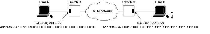
Figure 5-5 is an illustration of the soft PVP connections used in the examples in this section. Switch B and Switch C can be ATM switches or DSLAMs.
Figure 5-5 Soft Permanent Virtual Path Connection Example
To configure a soft PVP connection, perform these steps, beginning in global configuration mode:
Note
Example
This example shows how to configure a soft PVP on Switch B between interface 0/0, source VPI = 75, and Switch C, destination ATM address = 47.0091.8100.00.0000.1111.1111.1111.1111.1111.1111.00, VPI = 50 ( Figure 5-5):
Switch-B(config)# interface atm 0/0Switch-B(config-if)# atm soft-vp dest-address 75 47.0091.8100.00.0000.1111.1111.1111.1111.1111.1111.00 50To show the ATM virtual path configuration, use this EXEC command:
Examples
This example displays the soft VP configuration at Switch B, on interface 0/0 out to the ATM network:
Switch-B# show atm vpInterface VPI Type X-Interface X-VPI StatusATM0/0 75 SoftVP ATM4/0 50 UPThis example displays the soft VP configuration at Switch C, on interface 4/0 out to the ATM network:
Switch-C# show atm vpInterface VPI Type X-Interface X-VPI StatusATM4/0 50 SoftVP ATM0/0 75 UPThis example displays the soft VP configuration at Switch B, on interface 0/0, VPI = 75 out to the ATM network:
Switch-B# show atm vp interface atm 0/0 75Interface: ATM0/0, Type: suni-dualVPI = 75Status: TUNNELTime-since-last-status-change: 00:01:10Connection-type: SoftVPCast-type: point-to-pointSoft vp location: SourceRemote ATM address: 47.0091.8100.00.0000.1111.1111.1111.1111.1111.1111.00Remote VPI: 50Soft vp call state: InactiveNumber of soft vp re-try attempts: 4Slow-retry-interval: 60 secondsNext retry in: 4 secondsAggregate admin weight: 0Usage-Parameter-Control (UPC): passNumber of OAM-configured connections: 0OAM-configuration: disabledOAM-states: Not-applicableRx cells: 0, Tx cells: 0Rx connection-traffic-table-index: 1Rx service-category: UBR (Unspecified Bit Rate)Rx pcr-clp01: 7113539Rx scr-clp01: noneRx mcr-clp01: noneRx cdvt: 1024 (from default for interface)Rx mbs: noneTx connection-traffic-table-index: 1Tx service-category: UBR (Unspecified Bit Rate)Tx pcr-clp01: 7113539Tx scr-clp01: noneTx mcr-clp01: noneTx cdvt: noneTx mbs: noneThis example displays the soft VP configuration at Switch B, on interface 0/0, VPI = 75 out to the ATM network:
Switch-B# show atm vp interface atm 0/0 75Interface: ATM0/0, Type: suni-dualVPI = 75Status: TUNNELTime-since-last-status-change: 00:01:10Connection-type: SoftVPCast-type: point-to-pointSoft vp location: SourceRemote ATM address: 47.0091.8100.00.0000.1111.1111.1111.1111.1111.1111.00Remote VPI: 50Soft vp call state: InactiveNumber of soft vp re-try attempts: 4Slow-retry-interval: 60 secondsNext retry in: 4 secondsAggregate admin weight: 0Usage-Parameter-Control (UPC): passWrr weight: 32Number of OAM-configured connections: 0OAM-configuration: disabledOAM-states: Not-applicableThreshold Group: 5, Cells queued: 0Rx cells: 0, Tx cells: 0Tx Clp0:0, Tx Clp1: 0Rx Clp0:0, Rx Clp1: 0Rx Upc Violations:0, Rx cell drops:0Rx Clp0 q full drops:0, Rx Clp1 qthresh drops:0Rx connection-traffic-table-index: 1Rx service-category: UBR (Unspecified Bit Rate)Rx pcr-clp01: 7113539Rx scr-clp01: noneRx mcr-clp01: noneRx tolerance: 1024 (from default for interface)Tx connection-traffic-table-index: 1Tx service-category: UBR (Unspecified Bit Rate)Tx pcr-clp01: 7113539Tx scr-clp01: noneTx mcr-clp01: noneTx tolerance: noneConfiguring Non-Default Well-Known PVCs
Normally the default well-known VCs are automatically created with default VCIs. However, for the unusual instances where the DSLAM interfaces with nonstandard equipment, you can configure nondefault well-known VCI values on a per-interface basis.
Table 5-2 lists the default well-known VCs and their default configuration.
Table 5-2 Well-Known Virtual Channels
Signaling
0
5
ILMI
0
16
PNNI
0
18
Tag switching
0
32
Caution
Overview of Non-Default PVC Configuration
This section provides an overview of the steps you need to perform to configure non-default well-known VCs:
Step 1
Step 2
Step 3
•
•
•
Step 4
Configuring Non-Default PVCs
To configure the non-default VCs for signaling, ILMI, and PNNI, perform these steps, beginning in global configuration mode:
Note
Example
This example shows the non-default VC configuration steps:
Step 1
Step 2
Step 3
Step 4
Step 5
Step 6
Step 7
An example of this procedure is:
DSLAM# show atm vc interface atm 0/0Interface VPI VCI Type X-Interface X-VPI X-VCI Encap StatusATM0/0 0 5 PVC ATM0/0 0 49 QSAAL UPATM0/0 0 16 PVC ATM0/0 0 33 ILMI UPATM0/0 0 18 PVC ATM0/0 0 65 PNNI UPDSLAM#DSLAM# configure terminalEnter configuration commands, one per line. End with CNTL/Z.DSLAM(config)# interface atm 0/0DSLAM(config-if)# atm manual-well-known-vc deleteOkay to delete well-known VCs for this interface? [no]: yDSLAM(config-if)# exitDSLAM(config)# interface atm 0/0DSLAM(config-if)# atm pvc 1 35 interface atm0/0 0 any-vci encap qsaalDSLAM(config-if)# ^ZDSLAM#%SYS-5-CONFIG_I: Configured from console by consoleDSLAM# show atm vc interface atm 0/0Interface VPI VCI Type X-Interface X-VPI X-VCI Encap StatusATM0/0 1 35 PVC ATM0/0 0 150 QSAAL UPDSLAM# copy running-config startup-configBuilding configuration...[OK]
![]()
![]()
![]()
![]()
![]()
![]()
![]()
![]()
Posted: Fri Dec 3 14:05:48 PST 2004
All contents are Copyright © 1992--2004 Cisco Systems, Inc. All rights reserved.
Important Notices and Privacy Statement.