|
|

Table Of Contents
Configuring ATM Routing and PNNI
Configuring PNNI Without Hierarchy
Configuring the Lowest Level of the PNNI Hierarchy
Configuring Higher Levels of the PNNI Hierarchy
Configuring Statistics Collection
Configuring ATM Routing and PNNI
This chapter describes the Interim Interswitch Signaling Protocol (IISP) and Private Network-Network Interface (PNNI) ATM routing protocol implementations on Cisco DSLAMs with NI-2. This chapter includes
ATM Routing Overview
To place calls between ATM end systems, signaling consults an IISP, a static routing protocol, or PNNI. PNNI is a dynamic routing protocol that provides quality of service (QoS) routes to signaling based on the QoS requirements specified in the call setup request.
This section provides an overview of PNNI with a comparison to IISP.
Dynamic Routing
PNNI is a dynamic routing protocol for ATM. PNNI is dynamic because it learns the network topology and reachability information with minimal configuration. It automatically adapts to network changes by advertising topology state information.
In contrast, IISP is a static routing protocol. You must manually configure each route through the network. Because IISP static routing requires significant manual configuration and does not offer the scalability of PNNI hierarchy, it is best suited for use in small networks.
Source Routing
In a PNNI routing domain, the source ATM switch (or DSLAM) computes hierarchically complete routes for connection setups. This route information is included in the call setup signaling message.
In contrast, IISP uses hop-by-hop routing, where each switch or DSLAM that receives the connection setup message selects the next outgoing interface to which to forward the setup message. This selection is based on the mapping of destination addresses (in a routing table) to outgoing interfaces.
QoS Support
PNNI provides routes that satisfy quality of service (QoS) connection requests. PNNI selects routes through the network based on the administrative weight (AW) and other QoS parameters, such as
•
Available cell rate (AvCR)
•
•
•
The primary metric used by PNNI is AW. If a connection requests either maxCTD or CDV or both, PNNI may not be able to compute an optimum route through the network. However, PNNI guarantees a route that meets or exceeds the criteria of all specified QoS parameters.
In contrast, IISP does not provide QoS support.
PNNI Hierarchy
The primary goal of the PNNI hierarchy is scalability. However, you can also use the PNNI hierarchy for other needs, such as creating an administrative boundary. For example, you can use the PNNI hierarchy to hide the internal details of a peer group from switches outside of the peer group.
The key components of the PNNI hierarchy are:
•
•
•
•
The lowest level of the PNNI hierarchy contains lowest-level nodes only. No higher levels are possible if all nodes within a peer group are configured as lowest-level nodes. If your network is relatively small and scalability is not a problem, and the PNNI hierarchy is not required for other reasons, the benefits of a flat PNNI network may far outweigh the benefits of a hierarchical PNNI network. Refer to the "Configuring the Lowest Level of the PNNI Hierarchy" section for more information.
The peer group, PGL, and LGN define the hierarchy and are needed to create multiple levels of the PNNI hierarchy. Refer to the "Configuring Higher Levels of the PNNI Hierarchy" section for more information.
Figure 11-1 shows a flat network topology, where every node maintains information about every physical link in the network and reachability information for every other node in the network.
Figure 11-1 Flat Network Topology
Figure 11-2 shows a PNNI hierarchical network topology. In a PNNI hierarchical network, the number of nodes, links, and reachable address prefixes visible from any one switch in the network are reduced exponentially as the flat network is migrated to a hierarchical network.
Figure 11-2 PNNI Hierarchical Network Topology
PNNI hierarchy has certain advantages and disadvantages that you should consider before you decide to implement it in your network.
•
•
•
–
–
–
–
Because you must consider several factors, and their interdependency is not easily quantifiable, it is not possible to specify the exact number of nodes above which a flat network must be migrated to a hierarchical network. A high CPU load caused by PNNI control traffic is a strong indication that a hierarchical organization of the topology is required.
ATM Address Description
This section describes ATM addresses.
ATM Address Autoconfiguration
The DSLAM is equipped with a preconfigured 20-byte ATM address. This preconfigured address provides plug-and-play operation in isolated flat topology ATM networks. Although the preconfigured addresses are globally unique, they are not suitable for connection to service provider networks or within hierarchical PNNI networks. Furthermore, address summarization is not possible beyond the level of one switch.
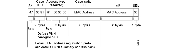
The preconfigured ATM address format provided by Cisco Systems is shown in Figure 11-3.
Figure 11-3 Cisco Default ATM Address
All preconfigured addresses share the same 7-byte address prefix. This prefix allows all lowest-level PNNI nodes to generate the same default peer group identifier at level 56. When you interconnect multiple switches, one large autoconfigured peer group is created at level 56. The next six bytes comprise the MAC address of the switch. The 7-byte address prefix combined with the 6-byte MAC address provide a 13-byte prefix that uniquely identifies each switch. This 13-byte prefix is also the default ILMI address prefix and is used by ILMI for address registration and summarization.
ATM Address Formats
The address formats used in PNNI are:
•
•
Note
E.164 AESA Prefixes
PNNI address prefixes are usually created by taking the first p (0 to 152) bits of an address. Because of the encoding defined for E.164 AESAs, this creates difficulties when native E.164 numbers are used with E.164 AESAs.
The encoding defined for E.164 AESAs in the ATM Forum UNI specifications is shown in Figure 11-4.
Figure 11-4 Normal Encoding of E.164 AESAs (Right-Justified)
In normal encoding, the international E.164 number is right-justified in the IDI part, with leading semi-octet zeros (0) used to fill any unused spaces. Because the international E.164 number varies in length and is right justified you must configure several E.164 AESA prefixes to represent reachability information to the international E.164 number prefix. These E.164 AESA prefixes differ only in the number of leading zeros between the AFI and the international E.164 number.
For example, all international E.164 numbers that represent destinations in Germany begin with the country code 49. The length of international E.164 numbers in Germany varies between 9
and 12 digits. To configure static routes to all E.164 numbers in Germany, configure static routes to this set of E.164 AESA prefixes:•
•
•
•
E.164 numbers that share a common prefix can be summarized by a single reachable address prefix, even when the corresponding set of full E.164 numbers varies in length. For this reason, in PNNI 2.0 the encoding of E.164 address prefixes is modified to a left-justified format, as shown in Figure 11-5.
Figure 11-5 PNNI 2.0 Encoding of E.164 AESAs (Left-Justified)
The left-justified encoding of the international E.164 number within the IDI allows for a single E.164 AESA prefix to represent reachability to all matching E.164 numbers, even when the matching E.164 numbers vary in length. Before PNNI routing looks up a destination address to find a route to that address, it converts the destination address from the call setup in the same way and then carries out the longest match lookup.
Note
The DSLAM supports the PNNI 2.0 encoding of E.164 AESAs with the aesa embedded-number left-justified command. When you enter this command, all reachable address prefixes with the E.164 AFI are automatically converted into the left-justified encoding format. This includes reachable address prefixes advertised by remote PNNI nodes, ATM static routes, summary address prefixes, routes learned by ILMI, and reachable address prefixes installed by the switch automatically (that is, representing the switch address and the soft PVC addresses on this switch). This affects the atm route, auto-summary, summary-address, show atm route, and show atm pnni summary commands. The atm address, atm prefix, and show atm addresses commands are not affected because they do not use PNNI address prefixes.
Note
Obtaining ATM Addresses
You can categorize ATM addresses by ownership: customer-owned ATM addresses and service provider ATM addresses.
If you have a private network, you can obtain ATM addresses from these sources:
•
•
In customer-owned ATM addresses, the main part of the address is allocated directly to a private networking customer by a national or world registration authority. A customer owned ATM address (owned by Cisco) is preconfigured on each DSLAM. If you do not implement a hierarchy in your PNNI network, you can use the preconfigured ATM address.
In service provider ATM addresses, the main part of the address is allocated to the network operator by the appropriate national or world registration authority. The operator may then suballocate part of the address space to customers.
ATM service providers can obtain these types of ATM addresses:
•
•
•
Designing an ATM Address Plan
Your ATM address plan is key to efficient operation and management of PNNI networks. When you design an ATM address plan, the most important points to remember are:
•
•
•
Globally Unique ATM Address Prefixes
You can obtain globally unique address prefixes from a national or world registration authority or they can be suballocated to you from a service provider's address space. Make sure that the addresses you assign in your network are derived from a globally unique address prefix, as shown in Figure 11-6.
Figure 11-6 Unique ATM Address Prefix Used to Assign ATM Addresses
For more information, refer to the "Obtaining ATM Addresses" section.
Hierarchical Addresses
The HO-DSP remainder, the part of the address between the assigned ATM address prefix and the ESI, should be assigned in a hierarchical manner. All systems in the network share the assigned ATM address prefix.
You can further subdivide the assigned address space by providing longer prefixes to different regions of the network. Within each peer group, be certain that the first level bits of each switch address matches the corresponding bits of the Peer Group Identifier (PGI) value. An example of a hierarchical address assignment is shown in Figure 11-7.
Figure 11-7 Sample Hierarchical Address Assignment
Note that the address prefix is longer at each lower level of the PNNI hierarchy shown in Figure 11-7.
The advantages of hierarchical address assignment include
•
•
When the ATM network topology (which consists of switches, links, and virtual path [VP] tunnels) differs from the logical topology (which consists of VPNs and virtual LANs), it is important that the address hierarchy follow the network topology. You can construct the logical topology using other features, such as emulated LANs or Closed User Groups (CUGs).
Planning for Future Growth
When you are constructing the address hierarchy, it is important to plan ahead for the maximum number of levels that you might need for future growth. Not all levels in the addressing hierarchy need to be used by PNNI. It is possible to run with fewer PNNI levels in the beginning, and then migrate to more levels of hierarchy in the future. For example, you can configure the network as one large peer group where the PGI value is based on the assigned ATM address prefix. By planning ahead, you can easily migrate to more levels of hierarchy without manually renumbering all of the switches and end systems.
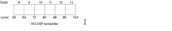
You can subdivide the HO-DSP remainder to allow for upward and downward future growth. For example, assume that you have 6 octets available for the HO-DSP remainder: 8 through 13 (as shown in Figure 11-8).
Figure 11-8 HO-DSP Remainder Subdivision Example
The HO-DSP remainder in this example spans levels 56 through 104. To allow for future expansion at the lowest level of the hierarchy, you must provide sufficient addressing space in the HO-DSP remainder to accommodate all future switches.
Assume that you start with the lowest level at 88. For administrative purposes, in the future you might want to group some of these switches into peer groups where additional switches will be added. For those switches that will be part of the new peer group you should assign addresses that can be easily clustered into a level 96 peer group. These addresses share a common 12th octet, leaving the 13th octet for downward future expansion.
The octet pairs (12 and 13) for these switches could be: (01, 00), (02, 00), (03, 00) and so on, while switches that will be added in the future could be: (02, 01), (02, 02), (02, 03) and so on.
This type of addressing scheme leaves room for expansion without requiring address modification. If you add a hierarchical level 96, the switches will form a new peer group at level 96.
Although you started with no more than 256 switches at the lowest level, by expanding this to two levels in the future, you are able to accommodate up to 65,536 switches in the same region.
Figure 11-9 shows an example of HO-DSP assignment.
Figure 11-9 Example of HO-DSP Assignment for Future Expansion
By following similar guidelines, you can plan for future expansion in the upward and downward direction. Specifically, you can expand upward by adding hierarchical levels as your network grows in size.
Configuring IISP
This section describes the procedures necessary for IISP configuration.
Configuring the Routing Mode
You can restrict the ATM routing software to operate in static mode. In this mode, call routing is restricted to only the static configuration of ATM routes, disabling operation of any dynamic ATM routing protocols, such as PNNI.
The atm routing-mode command is different from deleting all PNNI nodes using the node command and affects ILMI autoconfiguration. If the switch or DSLAM is configured using static routing mode on each interface, the switch ILMI variable atmfAtmLayerNniSigVersion is set to IISP. This causes either of these events to occur:
•
•
Note
To configure the routing mode, perform these steps, beginning in global configuration mode:
Example
This example shows how to use the atm routing-mode static command to restrict the switch operation to static routing mode and displays the result:
DSLAM(config)# atm routing-mode staticThis Configuration Will Not Take Effect Until Next Reload.DSLAM(config)# endDSLAM# copy running-config startup-configBuilding configuration...[OK]DSLAM# reloadDSLAM# show running-configBuilding configuration...Current configuration:!version 11.2no service padservice udp-small-serversservice tcp-small-servers!hostname DSLAM!!username dtateip rcmd remote-username dplatz!atm e164 translation-tablee164 address 1111111 nsap-address 11.111111111111111111111111.112233445566.11e164 address 2222222 nsap-address 22.222222222222222222222222.112233445566.22e164 address 3333333 nsap-address 33.333333333333333333333333.112233445566.33!atm routing-mode staticatm address 47.0091.8100.0000.0040.0b0a.2b81.0040.0b0a.2b81.00!interface CBR0/0no ip address<Information Deleted>This example shows how to reset the switch operation back to PNNI if the DSLAM is operating in static mode:
DSLAM(config)# no atm routing-mode staticThis Configuration Will Not Take Effect Until Next Reload.DSLAM(config)# endDSLAM# copy running-config startup-configBuilding configuration...[OK]DSLAM# reloadConfiguring the ATM Address
If you are planning to implement only a flat topology network (and have no future plans to migrate to PNNI hierarchy), you can skip this section and use the preconfigured ATM address assigned by Cisco Systems.
Note
To change the active ATM address follow these steps, beginning in global configuration mode:
Example
This example shows how to add the ATM address prefix 47.0091.8100.5670.000.0ca7.ce01 and remove the old address from the DSLAM and displays the result. Using the ellipses (...) adds the default Media Access Control (MAC) address as the last six bytes.
DSLAM(config)# atm address 47.0091.8100.5670.0000.0ca7.ce01...DSLAM(config)# no atm address 47.0091.8100.0000.0041.0b0a.1081...DSLAM# show atm addressesSwitch Address(es):47.00918100000000410B0A1081.00410B0A1081.00 active47.00918100567000000CA7CE01.00410B0A1081.00Soft VC Address(es):Soft VC Address(es):47.0091.8100.0000.007b.f444.7801.4000.0c80.0010.00 ATM0/147.0091.8100.0000.007b.f444.7801.4000.0c80.0020.00 ATM0/2ILMI Switch Prefix(es):47.0091.8100.0000.007b.f444.7801ILMI Configured Interface Prefix(es):LECS Address(es):Configuring Static Routes
Use the atm route command to configure a static route. A static route attached to an interface allows all ATM addresses matching the configured address prefix to be reached through that interface.
Note
To configure a static route, use this global configuration command:
Examples
This example uses the atm route command to configure a static route to the 13-byte switch prefix 47.00918100000000410B0A1081 to ATM interface 0/0:
DSLAM(config)# atm route 47.00918100000000410B0A1081 atm 0/0This example uses the atm route command to configure a static route to the 13-byte switch prefix 47.00918100000000410B0A1081 to ATM interface 0/0 configured with a scope 1 associated:
DSLAM(config)# atm route 47.0091.8100.0000 atm 0/0 scope 1This example shows the ATM static route configuration using the show atm route EXEC command:
DSLAM# show atm routeCodes: P - installing Protocol (S - Static, P - PNNI, R - Routing control),T - Type (I - Internal prefix, E - Exterior prefix, SE -Summary Exterior prefix, SI - Summary Internal prefix,ZE - Suppress Summary Exterior, ZI - Suppress Summary Internal)P T Node/Port St Lev Prefix~ ~~ ~~~~~~~~~~~~~~~~ ~~ ~~~ ~~~~~~~~~~~~~~~~~~~~~~~~~~~~~~~~~~~~~~~~~~~~~~~~~~~S E 1 ATM0/0 DN 56 47.0091.8100.0000/56S E 1 ATM0/0 DN 0 47.0091.8100.0000.00/64(E164 Address 1234567)R SI 1 0 UP 0 47.0091.8100.0000.0041.0b0a.1081/104R I 1 ATM0/0 UP 0 47.0091.8100.0000.0041.0b0a.1081.0041.0b0a.1081/152R I 1 ATM0/0 UP 0 47.0091.8100.0000.0041.0b0a.1081.4000.0c/128R SI 1 0 UP 0 47.0091.8100.5670.0000.0000.0000/104R I 1 ATM0/0 UP 0 47.0091.8100.5670.0000.0000.0000.0040.0b0a.1081/152R I 1 ATM0/0 UP 0 47.0091.8100.5670.0000.0000.0000.4000.0c/128Configuring PNNI
This section describes all of the procedures necessary for you to create a basic PNNI configuration.
Configuring PNNI Without Hierarchy
The DSLAM defaults to a working PNNI configuration suitable for operation in isolated flat topology ATM networks. The DSLAM comes with a globally unique preconfigured ATM address. Manual configuration is not required if you
•
•
•
If you plan to migrate your flat network topology to a PNNI hierarchical topology, proceed to the next section.
Configuring the Lowest Level of the PNNI Hierarchy
This section describes how to configure the lowest level of the PNNI hierarchy. The lowest-level nodes comprise the lowest level of the PNNI hierarchy. When only the lowest-level nodes are configured, there is no hierarchical structure. If your network is relatively small and you want the benefits of PNNI, but do not need the benefits of a hierarchical structure, follow the procedures in this section to configure the lowest level of the PNNI hierarchy.
To implement multiple levels of PNNI hierarchy, first complete the procedures in this section and then proceed to the "Configuring Higher Levels of the PNNI Hierarchy" section.
The lowest level PNNI configuration includes these procedures:
•
•
•
•
Configuring an ATM Address and PNNI Node Level
If you are planning to implement a:
•
•
The DSLAM is preconfigured as a single lowest-level PNNI node (locally identified as node 1) with a level of 56. The system calculates the node ID and peer group ID based on the current active ATM address.
To configure a node in a higher level of the PNNI hierarchy, the value of the node level must be a smaller number than the previous node. For example, a three-level hierarchical network could progress from level 72 to level 64 to level 56. Notice that the level numbers graduate from largest at the lowest level (72) to smallest at the highest level (56). (See Figure 11-7 earlier in this chapter.)
To change the active ATM address, create a new address, verify that it exists, and then delete the current active address. After you have entered the new ATM address, disable node 1 and then reenable it. At the same time, you can change the node level if required for your configuration. The identifiers for all higher level nodes are recalculated based on the new ATM address.
Caution
Note
To change the active ATM address, perform these steps, beginning in global configuration mode:
Example
This example changes the ATM address of the DSLAM from the autoconfigured address 47.0091.8100.0000.0041.0b0a.1081.0041.0b0a.1081.00 to the new address prefix 47.0091.8100.5670.0000.0000.1122.0041.0b0a.1081.00, and causes the node identifier and peer group identifier to be recalculated:
DSLAM(config)# atm address 47.0091.8100.5670.0000.0000.1122...DSLAM(config)# no atm address 47.0091.8100.0000.0041.0b0a.1081...DSLAM(config)# atm router pnniDSLAM(config-atm-router)# node 1 disableDSLAM(config-pnni-node)# node 1 enableThis example shows the PNNI node configuration using the show atm pnni local-node privileged EXEC command:
DSLAM# show atm pnni local-nodePNNI node 1 is enabled and runningNode name: eng_1System address 47.0091810000000002EB1FFE00.0002EB1FFE00.01Node ID 56:160:47.0091810000000002EB1FFE00.0002EB1FFE00.00Peer group ID 56:160:47.0000.0000.0000.0000.0000Level 56, Priority 0 0, No. of interfaces 1, No. of neighbors 0Parent Node Index: 2Node Allows Transit CallsNode Representation: simpleHello interval 15 sec, inactivity factor 5,Hello hold-down 10 tenths of secAck-delay 10 tenths of sec, retransmit interval 5 sec,Resource poll interval 5 secSVCC integrity times: calling 35 sec, called 50 sec,Horizontal Link inactivity time 120 sec,PTSE refresh interval 1800 sec, lifetime factor 200 percent,Min PTSE interval 10 tenths of secAuto summarization: on, Supported PNNI versions: newest 1, oldest 1Default administrative weight mode: uniformMax admin weight percentage: -1Next resource poll in 3 secondsMax PTSEs requested per PTSE request packet: 32Redistributing static routes: YesConfiguring Static Routes
Because PNNI is a dynamic routing protocol, static routes are not required between nodes that support PNNI. However, you can extend the routing capability of PNNI beyond nodes that support PNNI to
•
•
Use the atm route command to configure a static route. A static route attached to an interface allows all ATM addresses matching the configured address prefix to be reached through that interface.
Note
To configure a static route connection, use this global configuration command:
Examples
This example uses the atm route command to configure a static route to the 13-byte switch prefix 47.00918100000000410B0A1081 to ATM interface 0/0:
DSLAM(config)# atm route 47.00918100000000410B0A1081 atm 0/0This example uses the atm route command to configure a static route to the 13-byte switch prefix 47.00918100000000410B0A1081 to ATM interface 0/0 configured with a scope 1 associated:
DSLAM(config)# atm route 47.0091.8100.0000 atm 0/0 scope 1This example shows the ATM static route configuration using the show atm route EXEC command:
DSLAM# show atm routeCodes: P - installing Protocol (S - Static, P - PNNI, R - Routing control),T - Type (I - Internal prefix, E - Exterior prefix, SE -Summary Exterior prefix, SI - Summary Internal prefix,ZE - Suppress Summary Exterior, ZI - Suppress Summary Internal)P T Node/Port St Lev Prefix~ ~~ ~~~~~~~~~~~~~~~~ ~~ ~~~ ~~~~~~~~~~~~~~~~~~~~~~~~~~~~~~~~~~~~~~~~~~~~~~~~~~~S E 1 ATM0/0 DN 56 47.0091.8100.0000/56S E 1 ATM0/0 DN 0 47.0091.8100.0000.00/64(E164 Address 1234567)R SI 1 0 UP 0 47.0091.8100.0000.0041.0b0a.1081/104R I 1 ATM0/0 UP 0 47.0091.8100.0000.0041.0b0a.1081.0041.0b0a.1081/152R I 1 ATM0/0 UP 0 47.0091.8100.0000.0041.0b0a.1081.4000.0c/128R SI 1 0 UP 0 47.0091.8100.5670.0000.0000.0000/104R I 1 ATM0/0 UP 0 47.0091.8100.5670.0000.0000.0000.0040.0b0a.1081/152R I 1 ATM0/0 UP 0 47.0091.8100.5670.0000.0000.0000.4000.0c/128Configuring a Summary Address
You can configure summary addresses to reduce the amount of information advertised by a PNNI node and contribute to scalability in large networks. Each summary address consists of a single reachable address prefix that represents a collection of end system or node addresses.
We recommend that you use summary addresses when all end system addresses that match the summary address are directly reachable from the node. However, this is not always required because routes are always selected by nodes advertising the longest matching prefix to a destination address.
By default, each lowest-level node has a summary address equal to the 13-byte address prefix of the ATM address of the DSLAM. This address prefix is advertised into its peer group.
You can configure multiple addresses for a single DSLAM which are used during ATM address migration. ILMI registers end systems with multiple prefixes during this period until an old address is removed. PNNI automatically creates 13-byte summary address prefixes from all of its ATM addresses.
You must configure summary addresses (other than the defaults) on each node. Each node can have multiple summary address prefixes. Use the summary-address command to manually configure summary address prefixes.
Note
To configure a summary address, perform these steps, beginning in global configuration mode:
Examples
This example removes the default summary addresses and adds summary address 47.009181005670:
DSLAM(config)# atm router pnniDSLAM(config-atm-router)# node 1DSLAM(config-pnni-node)# no auto-summaryDSLAM(config-pnni-node)# summary-address 47.009181005670This example shows the ATM PNNI summary address configuration using the show atm pnni summary privileged EXEC command:
DSLAM# show atm pnni summaryCodes: Node - Node index advertising this summaryType - Summary type (INT - internal, EXT - exterior)Sup - Suppressed flag (Y - Yes, N - No)Auto - Auto Summary flag (Y - Yes, N - No)Adv - Advertised flag (Y - Yes, N - No)Node Type Sup Auto Adv Summary Prefix~~~~ ~~~~ ~~~ ~~~~ ~~~ ~~~~~~~~~~~~~~~~~~~~~~~~~~~~~~~~~~~~~~~~~~~~~~~~~~~1 Int N Y Y 47.0091.8100.0000.0040.0b0a.2a81/1042 Int N Y N 47.01b1.0000.0000.0000.00/80Configuring Scope Mapping
The PNNI address scope allows you to restrict advertised reachability information within configurable boundaries.
Note
In PNNI networks, the scope is specified in terms of PNNI levels. The mapping from organizational scope values used at UNI and IISP interfaces to PNNI levels is configured on the lowest-level node. The mapping can be determined automatically (which is the default setting) or manually, depending on the configuration of the scope mode command.
In manual mode, if you modify the level of node 1, make sure you also reconfigure the scope map to avoid unintended suppression of reachability advertisements. Misconfiguring the scope map could cause addresses to remain unadvertised.
In automatic mode, the UNI to PNNI level mapping is automatically reconfigured each time the level of the node 1 is modified. The automatic reconfiguration prevents misconfigurations caused by node level modifications. Automatic adjustment of scope mapping uses the values shown in Table 11-1.
If you enter the scope mode automatic command, this ensures that all organizational scope values cover an area at least as wide as the current node's peer group. Configuring the scope mode to manual disables this feature and no changes can be made without explicit configuration.
To configure the PNNI scope mapping, perform these steps, beginning in global configuration mode:
atm router pnni
At the configure prompt, enter ATM router PNNI mode from the terminal. The prompt changes to DSLAM(config-atm-router)#.
node node_index
At the configure ATM router prompt, enter node configuration mode. The prompt changes to DSLAM(config-pnni-node)#.
scope mode {automatic | manual}
Configure scope mode as manual.1
scope map low-org-scope [high-org-scope] level level-number
Configure node scope mapping.
1 You must enter the scope mode manual command to allow scope mapping configuration.
Example
This example shows how to configure PNNI scope mapping manually so that organizational scope values 1 through 8 map to PNNI level 72 and displays the result:
DSLAM(config)# atm router pnniDSLAM(config-atm-router)# node 1DSLAM(config-pnni-node)# scope mode manualDSLAM(config-pnni-node)# scope map 1 8 level 72DSLAM# show atm pnni scopeUNI scope PNNI Level~~~~~~~~~ ~~~~~~~~~~(1 - 10) 56(11 - 12) 48(13 - 14) 32(15 - 15) 0Scope mode: manualConfiguring Higher Levels of the PNNI Hierarchy
This section describes the procedures to configure higher levels of PNNI hierarchy.
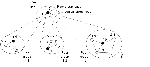
After you have configured the lowest level of the PNNI hierarchy (see the section, "Configuring the Lowest Level of the PNNI Hierarchy" section), you can complete the PNNI hierarchical structure by configuring peer group leaders (PGLs) and logical group nodes (LGNs).
Each peer group can contain one active PGL. The PGL is a logical node within the peer group that collects data about the peer group to represent it as a single node to the next PNNI hierarchical level.
Upon becoming a PGL, the PGL creates a parent LGN. The LGN represents the PGL's peer group within the next higher level peer group. The LGN aggregates and summarizes information about its child peer group and floods that information into its own peer group.
The LGN also distributes information received from its peer group to the PGL of its child peer group for flooding. Figure 11-10 shows an example of PGLs and LGNs.
Figure 11-10 PGLs and LGNs
To create the PNNI hierarchy, select DSLAMs that are eligible to become PGLs at each level of the hierarchy. Nodes can become PGLs through the peer group leader election process. Each node has a configured election priority.
To be eligible for election, the configured priority must be greater than zero and a parent node must be configured. Normally the node with the highest configured leadership priority in a peer group is elected PGL. You can configure multiple nodes in a peer group with a non-zero leadership priority so that if one PGL becomes unreachable, the node configured with the next highest election leadership priority becomes the new PGL.
Note
Because any one peer group can consist of both lowest level nodes and LGNs, lowest level nodes should be preferred as PGLs. Configuring the network hierarchy with multiple LGNs at the same DSLAM creates additional PNNI processing and results in slower recovery from failures. Selecting DSLAMs for election with more processing capability (for example, because a smaller volume of call processing compared to others) may be better.
We recommend that each node in a peer group that can become a PGL be assigned the same parent node configuration.
Configuring a Logical Group Node and Peer Group Identifier
You can configure a new LGN by entering the node command with an unused node index value between 2 and 8.
The LGN is created only when the child node in the same DSLAM (that is, the node whose parent configuration points to this node) is elected PGL of the child peer group.
The peer group identifier defaults to a value created from the first part of the child peer group identifier, and does not need to be specified. If you want a non-default peer group identifier, you must configure all logical nodes within a peer group with the same peer group identifier.
Higher level nodes only become active if
•
•
To configure a LGN and peer group identifier, perform these steps, beginning in global configuration mode:
Example
This example shows how to create a new node 2 with a level of 56 and a peer group identifier of 56:47009111223344 and displays the result. Notice that the PNNI level and the first two digits of the peer group identifier are the same:
DSLAM(config)# atm router pnniDSLAM(config-atm-router)# node 2 level 56 peer-group-identifier 56:47009111223344 enableDSLAM(config-pnni-node)# endDSLAM# show atm pnni local-node 2PNNI node 2 is enabled and not runningNode name: Switch.2.56System address 47.009181000000000000000001.000000000001.02Node ID 56:0:00.000000000000000000000000.000000000001.00Peer group ID 56:47.0091.1122.3344.0000.0000.0000Level 56, Priority 0 0, No. of interfaces 0, No. of neighbors 0Parent Node Index: NONENode Allows Transit CallsNode Representation: simpleHello interval 15 sec, inactivity factor 5,Hello hold-down 10 tenths of secAck-delay 10 tenths of sec, retransmit interval 5 sec,Resource poll interval 5 secSVCC integrity times: calling 35 sec, called 50 sec,Horizontal Link inactivity time 120 sec,PTSE refresh interval 1800 sec, lifetime factor 200 percent,Min PTSE interval 10 tenths of secAuto summarization: on, Supported PNNI versions: newest 1, oldest 1Default administrative weight mode: uniformMax admin weight percentage: -1Max PTSEs requested per PTSE request packet: 32Redistributing static routes: NoConfiguring the Node Name
PNNI node names default to names based on the host name. For example, if the host name is SanFran1, the default node name is also SanFran1. If you prefer node names that more accurately reflect the peer group, you can use the name command to change the default node name. For example, you could change the node name to Cal1 to represent the entire location of the peer group to which it belongs. Cisco recommends you choose a node name of 12 characters or less so that your screen displays remain well formatted and easy to read.
After you configure a node name, the system distributes it to all other nodes by PNNI flooding. This allows the node to be identified by its node name in PNNI show commands.
To configure the PNNI node name, perform these steps, beginning in global configuration mode:
Example
This example configures the name of the node as eng_1 using the name command, and displays the result:
DSLAM(config)# atm router pnniDSLAM(config-atm-router)# node 1DSLAM(config-pnni-node)# name eng_1DSLAM# show atm pnni local-nodePNNI node 1 is enabled and runningNode name: eng_1System address 47.0091810000000002EB1FFE00.0002EB1FFE00.01Node ID 56:160:47.0091810000000002EB1FFE00.0002EB1FFE00.00Peer group ID 56:16.0347.0000.0000.0000.0000.0000Level 56, Priority 0 0, No. of interfaces 1, No. of neighbors 0Parent Node Index: 2Node Allows Transit CallsNode Representation: simpleHello interval 15 sec, inactivity factor 5,Hello hold-down 10 tenths of secAck-delay 10 tenths of sec, retransmit interval 5 sec,Resource poll interval 5 secSVCC integrity times: calling 35 sec, called 50 sec,Horizontal Link inactivity time 120 sec,PTSE refresh interval 1800 sec, lifetime factor 200 percent,Min PTSE interval 10 tenths of secAuto summarization: on, Supported PNNI versions: newest 1, oldest 1Default administrative weight mode: uniformMax admin weight percentage: -1Next resource poll in 3 secondsMax PTSEs requested per PTSE request packet: 32Redistributing static routes: YesConfiguring a Parent Node
For a node to be eligible to become a PGL within its own peer group, you must configure a parent node and an election leadership level (described in the section "Configuring the Node Election Leadership Priority" section). If the node is elected a PGL, the node specified by the parent command becomes the parent node and represents the peer group at the next hierarchical level.
To configure a parent node, perform these steps, beginning in global configuration mode:
Example
This example creates a parent node for node 1 and displays the result:
DSLAM(config)# atm router pnniDSLAM(config-pnni-node)# node 1DSLAM(config-pnni-node)# parent 2DSLAM# show atm pnni hierarchyLocally configured parent nodes:Node ParentIndex Level Index Local-node Status Node Name~~~~~ ~~~~~ ~~~~~~ ~~~~~~~~~~~~~~~~~~~~ ~~~~~~~~~~~~~~~~~~~~~~1 80 2 Enabled/ Running DSLAM2 72 N/A Enabled/ Running DSLAM.2.72Configuring the Node Election Leadership Priority
Normally the node with the highest election leadership priority is elected PGL. If two nodes share the same election priority, the node with the highest node identifier becomes the PGL. To be eligible for election, ensure that the configured priority is greater than zero. You can configure multiple nodes in a peer group with non-zero leadership priority so that if one PGL becomes unreachable, the node configured with the next highest election leadership priority becomes the new PGL.
Note
The control for election is done through the assignment of leadership priorities. We recommend that the leadership priority space be divided into three tiers:
•
•
•
This subdivision exists because of the GroupLeaderIncrement variable. When a node becomes PGL, it increases the advertised leadership priority by a value of 50 to avoid instabilities after election.
Keep nodes that you do not want to become PGLs assigned to a default leadership priority value of 0.
If among the PGL candidates no node must be forced to be PGL, then assign all leadership priority values within the first tier. After a node is elected PGL, it remains PGL until it steps down a tier or is configured to step down.
If certain nodes must take precedence over nodes in the first tier, even if one is already PGL, leadership priority values can be assigned from the second tier. We recommend that you configure more than one node with a leadership priority value from the second tier. This prevents one unstable node with a larger leadership priority value from destabilizing the peer group repeatedly.
If you need a strict master leader, use the third tier.
Note
To configure the election leadership priority, perform these steps, beginning in global configuration mode:
Example
This example changes the election leadership priority for node 1 to 100 and displays the result:
DSLAM(config)# atm router pnniDSLAM(config-pnni-node)# node 1DSLAM(config-pnni-node)# election leadership-priority 100DSLAM# show atm pnni electionPGL Status.............: PGLPreferred PGL..........: (1) SwitchPreferred PGL Priority.: 255Active PGL.............: (1) SwitchActive PGL Priority....: 255Active PGL For.........: 00:01:07Current FSM State......: PGLE Operating: PGLLast FSM State.........: PGLE Awaiting UnanimityLast FSM Event.........: Unanimous VoteConfigured Priority....: 205Advertised Priority....: 255Conf. Parent Node Index: 2PGL Init Interval......: 15 secsSearch Peer Interval...: 75 secsRe-election Interval...: 15 secsOverride Delay.........: 30 secsThis example shows all nodes in the peer group using the show atm pnni election peers command:
DSLAM# show atm pnni election peersNode No. Priority Connected Preferred PGL~~~~~~~~ ~~~~~~~~ ~~~~~~~~~ ~~~~~~~~~~~~~1 255 Yes Switch9 0 Yes Switch10 0 Yes Switch11 0 Yes Switch12 0 Yes SwitchConfiguring a Summary Address
You can use summary addresses to decrease the amount of information advertised by a PNNI node, and thereby contribute to scaling in large networks. Each summary address consists of a single reachable address prefix that represents a collection of end system or node addresses that begin with the given prefix. Only use summary addresses when all end system addresses that match the summary address are directly reachable from this node. However, this is not always required because routes are always selected to nodes advertising the longest matching prefix to a destination address.
Configure a single default summary address for each logical group node (LGN) in the PNNI hierarchy. The length of that summary for any LGN equals the level of the child peer group, and its value is equal to the first level bits of the child peer group identifier. This address prefix is advertised into the LGN's peer group.
Explicitly configure summary addresses other than defaults on each node. Use the summary-address command to manually configure summary address prefixes. A node can have multiple summary address prefixes.
Assign the same summary address lists to each node in a peer group that has a potential to become a PGL for its parent node configuration.
Note
To configure the ATM PNNI summary address prefix, perform these steps, beginning in global configuration mode:
Example
This example shows how to remove the default summary addresses and add summary address 47.009181005670 and displays the result:
DSLAM(config)# atm router pnniDSLAM(config-atm-router)# node 1DSLAM(config-pnni-node)# no auto-summaryDSLAM(config-pnni-node)# summary-address 47.009181005670DSLAM# show atm pnni summaryCodes: Node - Node index advertising this summaryType - Summary type (INT - internal, EXT - exterior)Sup - Suppressed flag (Y - Yes, N - No)Auto - Auto Summary flag (Y - Yes, N - No)Adv - Advertised flag (Y - Yes, N - No)Node Type Sup Auto Adv Summary Prefix~~~~ ~~~~ ~~~ ~~~~ ~~~ ~~~~~~~~~~~~~~~~~~~~~~~~~~~~~~~~~~~~~~~~~~~~~~~~~~~1 Int N Y Y 47.0091.8100.0000.0040.0b0a.2a81/1042 Int N Y N 47.01b1.0000.0000.0000.00/80PNNI Hierarchy Configuration Example
An example configuration for a three-level hierarchical topology is shown in Figure 11-11. The example shows the configuration of only 5 switches, although you can configure several other switches in each peer group.
Figure 11-11 Example Three-Level Hierarchical Topology
At the lowest level (level 72), the hierarchy represents two separate peer groups. Each of the four switches named T2 to T5 are eligible to become a PGL at two levels, and each has two configured ancestor nodes (a parent node or a parent node's parent).
Switch T1 has no configured ancestor nodes and is not eligible to become a PGL. As a result of the peer group leader election at the lowest level, switches T4 and T3 become leaders of their peer groups. Therefore, each switch creates an LGN at the second level (level 64) of the hierarchy.
As a result of the election at the second level of the hierarchy, logical group nodes SanFran.BldA and NewYork.BldB are elected as PGLs, creating logical group nodes at the highest level of the hierarchy (Level 56). At that level, the uplinks induced through level 64 form an aggregated horizontal link within the common peer group at level 56.
Examples
The examples that follow show the configurations for each switch and the outputs of the show atm pnni local-node command.
Switch NewYork.BldB.T1 Configuration
hostname NewYork.BldB.T1atm address 47.0091.4455.6677.1144.1011.1233.0060.3e7b.3a01.00atm router pnninode 1 level 72 lowestredistribute atm-staticNewYork.BldB.T1# show atm pnni local-nodePNNI node 1 is enabled and runningNode name: NewYork.BldB.T1System address 47.009144556677114410111233.00603E7B3A01.01Node ID 72:160:47.009144556677114410111233.00603E7B3A01.00Peer group ID 72:47.0091.4455.6677.1144.0000.0000Level 72, Priority 0 0, No. of interfaces 3, No. of neighbors 2Parent Node Index: NONE<information deleted>Switch NewYork.BldB.T2 Configuration
hostname NewYork.BldB.T2atm address 47.0091.4455.6677.1144.1011.1244.0060.3e5b.bc01.00atm router pnninode 1 level 72 lowestparent 2redistribute atm-staticelection leadership-priority 40node 2 level 64parent 3election leadership-priority 40name NewYork.BldBnode 3 level 56name NewYorkNewYork.BldB.T2# show atm pnni local-nodePNNI node 1 is enabled and runningNode name: NewYork.BldB.T2System address 47.009144556677114410111244.00603E5BBC01.01Node ID 72:160:47.009144556677114410111244.00603E5BBC01.00Peer group ID 72:47.0091.4455.6677.1144.0000.0000Level 72, Priority 40 40, No. of interfaces 3, No. of neighbors 1Parent Node Index: 2<information deleted>PNNI node 2 is enabled and not runningNode name: NewYork.BldBSystem address 47.009144556677114410111244.00603E5BBC01.02Node ID 64:72:47.009144556677114400000000.00603E5BBC01.00Peer group ID 64:47.0091.4455.6677.1100.0000.0000Level 64, Priority 40 40, No. of interfaces 0, No. of neighbors 0Parent Node Index: 3<information deleted>PNNI node 3 is enabled and not runningNode name: NewYorkSystem address 47.009144556677114410111244.00603E5BBC01.03Node ID 56:64:47.009144556677110000000000.00603E5BBC01.00Peer group ID 56:47.0091.4455.6677.0000.0000.0000Level 56, Priority 0 0, No. of interfaces 0, No. of neighbors 0Parent Node Index: NONE<information deleted>Switch NewYork.BldB.T3 Configuration
hostname NewYork.BldB.T3atm address 47.0091.4455.6677.1144.1011.1255.0060.3e5b.c401.00atm router pnninode 1 level 72 lowestparent 2redistribute atm-staticelection leadership-priority 45node 2 level 64parent 3election leadership-priority 45name NewYork.BldBnode 3 level 56name NewYorkNewYork.BldB.T3# show atm pnni local-nodePNNI node 1 is enabled and runningNode name: NewYork.BldB.T3System address 47.009144556677114410111255.00603E5BC401.01Node ID 72:160:47.009144556677114410111255.00603E5BC401.00Peer group ID 72:47.0091.4455.6677.1144.0000.0000Level 72, Priority 45 95, No. of interfaces 4, No. of neighbors 1Parent Node Index: 2<information deleted>PNNI node 2 is enabled and runningNode name: NewYork.BldBSystem address 47.009144556677114410111255.00603E5BC401.02Node ID 64:72:47.009144556677114400000000.00603E5BC401.00Peer group ID 64:47.0091.4455.6677.1100.0000.0000Level 64, Priority 45 95, No. of interfaces 0, No. of neighbors 0Parent Node Index: 3<information deleted>PNNI node 3 is enabled and runningNode name: NewYorkSystem address 47.009144556677114410111255.00603E5BC401.03Node ID 56:64:47.009144556677110000000000.00603E5BC401.00Peer group ID 56:47.0091.4455.6677.0000.0000.0000Level 56, Priority 0 0, No. of interfaces 0, No. of neighbors 1Parent Node Index: NONE<information deleted>Switch SanFran.BldA.T4 Configuration
hostname SanFran.BldA.T4atm address 47.0091.4455.6677.2233.1011.1266.0060.3e7b.2001.00atm router pnninode 1 level 72 lowestparent 2redistribute atm-staticelection leadership-priority 45node 2 level 64parent 3election leadership-priority 45name SanFran.BldAnode 3 level 56name SanFranSanFran.BldA.T4# show atm pnni local-nodePNNI node 1 is enabled and runningNode name: SanFran.BldA.T4System address 47.009144556677223310111266.00603E7B2001.01Node ID 72:160:47.009144556677223310111266.00603E7B2001.00Peer group ID 72:47.0091.4455.6677.2233.0000.0000Level 72, Priority 45 95, No. of interfaces 4, No. of neighbors 1Parent Node Index: 2<information deleted>PNNI node 2 is enabled and runningNode name: SanFran.BldASystem address 47.009144556677223310111266.00603E7B2001.02Node ID 64:72:47.009144556677223300000000.00603E7B2001.00Peer group ID 64:47.0091.4455.6677.2200.0000.0000Level 64, Priority 45 95, No. of interfaces 0, No. of neighbors 0Parent Node Index: 3<information deleted>PNNI node 3 is enabled and runningNode name: SanFranSystem address 47.009144556677223310111266.00603E7B2001.03Node ID 56:64:47.009144556677220000000000.00603E7B2001.00Peer group ID 56:47.0091.4455.6677.0000.0000.0000Level 56, Priority 0 0, No. of interfaces 0, No. of neighbors 1Parent Node Index: NONE<information deleted>Switch SanFran.BldA.T5 Configuration
hostname SanFran.BldA.T5atm address 47.0091.4455.6677.2233.1011.1244.0060.3e7b.2401.00atm router pnninode 1 level 72 lowestparent 2redistribute atm-staticelection leadership-priority 10node 2 level 64parent 3election leadership-priority 40name SanFran.BldAnode 3 level 56name SanFranSanFran.BldA.T5# show atm pnni local-nodePNNI node 1 is enabled and runningNode name: SanFran.BldA.T5System address 47.009144556677223310111244.00603E7B2401.01Node ID 72:160:47.009144556677223310111244.00603E7B2401.00Peer group ID 72:47.0091.4455.6677.2233.0000.0000Level 72, Priority 10 10, No. of interfaces 2, No. of neighbors 1Parent Node Index: 2<information deleted>PNNI node 2 is enabled and not runningNode name: SanFran.BldASystem address 47.009144556677223310111244.00603E7B2401.02Node ID 64:72:47.009144556677223300000000.00603E7B2401.00Peer group ID 64:47.0091.4455.6677.2200.0000.0000Level 64, Priority 40 40, No. of interfaces 0, No. of neighbors 0Parent Node Index: 3<information deleted>PNNI node 3 is enabled and not runningNode name: SanFranSystem address 47.009144556677223310111244.00603E7B2401.03Node ID 56:64:47.009144556677220000000000.00603E7B2401.00Peer group ID 56:47.0091.4455.6677.0000.0000.0000Level 56, Priority 0 0, No. of interfaces 0, No. of neighbors 0Parent Node Index: NONE<information deleted>Advanced PNNI Configuration
This section describes how to configure advanced PNNI features. The advanced features described in this section are not required to enable PNNI, but are provided to assist you in tuning your network performance.
Tuning Route Selection
This section describes how to tune the route selection in your PNNI network:
•
•
•
•
Configuring Background Route Computation
The DSLAM supports these route selection modes:
•
•
The background routes mode should be enabled in large networks where it will usually exhibit less-stringent processing requirements and better scalability. Route computation is performed at almost every poll interval when a significant change in the topology of the network is reported or when significant threshold changes have occurred since the last route computation.
To configure the background route computation, perform these steps, beginning in global configuration mode:
Examples
This example shows how to enable background routes and configures the background routes poll interval to 30 seconds:
DSLAM(config)# atm router pnniDSLAM(config-atm-router)# background-routes-enable poll-interval 30This example shows the ATM PNNI background route configuration using the show atm pnni background status privileged EXEC command:
DSLAM# show atm pnni background statusBackground Route Computation is EnabledBackground Interval is set at 10 secondsBackground Insignificant Threshold is set at 32This example shows the ATM PNNI background route tables for CBR using the show atm pnni background routes privileged EXEC command:
DSLAM# show atm pnni background routes cbrBackground Routes From CBR/AW Table~~~~~~~~~~~~~~~~~~~~~~~~~~~~~~~~~~~~~~2 Routes To Node 21. Hops 1. 1:ATM0/2 -> 2->: aw 5040 cdv 138 ctd 154 acr 147743 clr0 10 clr01 10<-: aw 5040 cdv 138 ctd 154 acr 147743 clr0 10 clr01 102. Hops 1. 1:ATM0/1 -> 2->: aw 5040 cdv 138 ctd 154 acr 147743 clr0 10 clr01 10<-: aw 5040 cdv 138 ctd 154 acr 147743 clr0 10 clr01 101 Routes To Node 51. Hops 1. 1:ATM1/0 -> 5->: aw 5040 cdv 138 ctd 154 acr 147743 clr0 10 clr01 10<-: aw 5040 cdv 138 ctd 154 acr 147743 clr0 10 clr01 10Background Routes From CBR/CDV Table~~~~~~~~~~~~~~~~~~~~~~~~~~~~~~~~~~~~~~2 Routes To Node 21. Hops 1. 1:ATM0/2 -> 2->: aw 5040 cdv 138 ctd 154 acr 147743 clr0 10 clr01 10<-: aw 5040 cdv 138 ctd 154 acr 147743 clr0 10 clr01 102. Hops 1. 1:ATM0/1 -> 2->: aw 5040 cdv 138 ctd 154 acr 147743 clr0 10 clr01 10<-: aw 5040 cdv 138 ctd 154 acr 147743 clr0 10 clr01 101 Routes To Node 51. Hops 1. 1:ATM0/1 -> 5->: aw 5040 cdv 138 ctd 154 acr 147743 clr0 10 clr01 10<-: aw 5040 cdv 138 ctd 154 acr 147743 clr0 10 clr01 10Background Routes From CBR/CTD Table~~~~~~~~~~~~~~~~~~~~~~~~~~~~~~~~~~~~~~2 Routes To Node 21. Hops 1. 1:ATM0/1 -> 2->: aw 5040 cdv 138 ctd 154 acr 147743 clr0 10 clr01 10<-: aw 5040 cdv 138 ctd 154 acr 147743 clr0 10 clr01 102. Hops 1. 1:ATM0/1 -> 2->: aw 5040 cdv 138 ctd 154 acr 147743 clr0 10 clr01 10<-: aw 5040 cdv 138 ctd 154 acr 147743 clr0 10 clr01 101 Routes To Node 51. Hops 1. 1:ATM0/1 -> 5->: aw 5040 cdv 138 ctd 154 acr 147743 clr0 10 clr01 10<-: aw 5040 cdv 138 ctd 154 acr 147743 clr0 10 clr01 10Background Routes From CBR/CTD Table~~~~~~~~~~~~~~~~~~~~~~~~~~~~~~~~~~~~~~2 Routes To Node 21. Hops 1. 1:ATM0/1 -> 2->: aw 5040 cdv 138 ctd 154 acr 147743 clr0 10 clr01 10<-: aw 5040 cdv 138 ctd 154 acr 147743 clr0 10 clr01 102. Hops 1. 1:ATM0/2 -> 2->: aw 5040 cdv 138 ctd 154 acr 147743 clr0 10 clr01 10<-: aw 5040 cdv 138 ctd 154 acr 147743 clr0 10 clr01 101 Routes To Node 51. Hops 1. 1:ATM0/1 -> 5->: aw 5040 cdv 138 ctd 154 acr 147743 clr0 10 clr01 10<-: aw 5040 cdv 138 ctd 154 acr 147743 clr0 10 clr01 10Configuring Link Selection
The link selection feature allows you to choose the mode for selecting one specific link among several parallel links to the same neighbor node (for example, links between two adjacent switches).
When multiple parallel links are configured inconsistently, the order of precedence of configured values is as follows:
1.
2.
3.
4.
For example, if any link is configured as admin-weight minimize, that link is used for the entire link group.
To configure the PNNI link selection for, perform these steps, beginning in global configuration mode:
Example
This example shows how to configure ATM interface 0/0 to use the transmit-speed-maximize link selection mode and displays the result:
DSLAM(config)# interface atm 0/0DSLAM(config-if)# atm pnni link-selection transmit-speed-maximizeDSLAM# show atm pnni neighborNeighbor Name: eng_22, Node number: 2Neighbor Node Id: 56:160:47.0091810000000003DDE74601.0003DDE74601.00Neighboring Peer State: FullLink Selection Set To: minimize blocking of future callsPort Remote port ID Hello stateATM0/1 ATM1/2 (81902000) 2way_inATM0/2 ATM1/0 (81901000) 2way_in (Flooding Port)Configuring the Maximum Administrative Weight Percentage
The maximum AW percentage feature allows you to prevent the use of alternate routes that consume too many network resources. This feature provides a generalized form of a hop count limit. The maximum acceptable administrative weight is equal to the specified percentage of the least administrative weight of any route to the destination (from the background routing tables). For example, if the least administrative weight to the destination is 5040 and the configured percentage is 300, the maximum acceptable administrative weight for the call is 5040 * 300 / 100 or 15120.
To configure the maximum AW percentage, perform these steps, beginning in global configuration mode:
Note
Example
This example shows how to configure the node maximum AW percentage value as 300 and displays the result:
DSLAM(config)# atm router pnniDSLAM(config-atm-router)# max-admin-weight-percentage 300DSLAM# show atm pnni local-nodePNNI node 1 is enabled and runningNode name: eng_1System address 47.009181000000000000001212.121212121212.00Node ID 56:160:47.009181000000000000001212.121212121212.00Peer group ID 56:47.0091.8100.0000.0000.0000.0000Level 56, Priority 0, No. of interface 4, No. of neighbor 1Hello interval 15 sec, inactivity factor 5, Hello hold-down 10 tenths of secAck-delay 2 sec, retransmit interval 10 sec, rm-poll interval 10 secPTSE refresh interval 90 sec, lifetime factor 7, minPTSEinterval 1000 msecAuto summarization: on, Supported PNNI versions: newest 1, oldest 1Default administrative weight mode: linespeedMax admin weight percentage: 300Next RM poll in 3 secondsConfiguring the Precedence
The route selection algorithm chooses routes to particular destinations using the longest match reachable address prefixes known to the DSLAM. When there are multiple longest match reachable address prefixes known to the DSLAM, the route selection algorithm first attempts to find routes to reachable addresses with types of greatest precedence. Among multiple longest match reachable address prefixes of the same type, routes with the least total AW are chosen first.
Local internal reachable addresses, whether learned through ILMI or as static routes, receive highest precedence or a precedence value of one. The precedence of other reachable address types is configurable.
To configure the precedence of reachable addresses, perform these steps, beginning in global configuration mode:
Example
This example shows how to configure all PNNI remote exterior routes with a precedence value of 4 and displays the result:
DSLAM(config)# atm router pnniDSLAM(config-atm-router)# precedence pnni-remote-exterior 4DSLAM# show atm pnni precedenceWorking DefaultPrefix Poa Type Priority Priority----------------------------- -------- --------local-internal 1 1static-local-internal-metrics 2 2static-local-exterior 3 3static-local-exterior-metrics 2 2pnni-remote-internal 2 2pnni-remote-internal-metrics 2 2pnni-remote-exterior 4 4pnni-remote-exterior-metrics 2 2Tuning Topology Attributes
This section describes how to configure attributes that affect the network topology.
Configuring the Global Administrative Weight Mode
Administrative weight is the primary routing metric for minimizing use of network resources. You can configure the administrative weight (AW) to indicate the relative desirability of using a link. In addition to the per-interface atm pnni administrative-weight command, the ATM router PNNI administrative-weight command can be used to change the default AW assignment. For example, you can assign equal AWs to all links in the network to minimize the number of hops used by each connection.
To configure the administrative weight mode, perform these steps, beginning in global configuration mode:
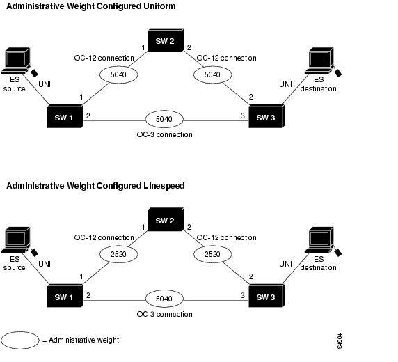
Figure 11-12 is an example of the effect of AW on call routing. The network depicted at the top of Figure 11-12 is configured as uniform, causing equal AW to be assigned to each link. The identical network at the bottom of the figure is configured as line speed.
The links between SW1 and SW2 (SW1p1 to SW2p1) and SW2 and SW3 (SW2p2 to SW3p2) are both faster OC-12 connections and have lower AWs. PNNI interprets the route over the two OC-12 links as being administratively equivalent to a more direct route between SW1 and SW3 using the OC-3 connection.
Figure 11-12 Network Administrative Weight Example
Example
This example shows how to configure AW for the node as line speed and displays the result:
DSLAM(config)# atm router pnniDSLAM(config-atm-router)# administrative-weight linespeedDSLAM# show atm pnni local-nodePNNI node 1 is enabled and runningNode name: DSLAMSystem address 47.009181000000000000001212.121212121212.00Node ID 56:160:47.009181000000000000001212.121212121212.00Peer group ID 56:47.0091.8100.0000.0000.0000.0000Level 56, Priority 0, No. of interface 4, No. of neighbor 1Hello interval 15 sec, inactivity factor 5, Hello hold-down 10 tenths of secAck-delay 2 sec, retransmit interval 10 sec, rm-poll interval 10 secPTSE refresh interval 90 sec, lifetime factor 7, minPTSEinterval 1000 msecAuto summarization: on, Supported PNNI versions: newest 1, oldest 1Default administrative weight mode: linespeedMax admin weight percentage: 300Next RM poll in 3 secondsConfiguring Administrative Weight per Interface
AW is the main metric used for computation of the paths by PNNI. The assignment of AWs to links and nodes affects the way PNNI selects paths in the private ATM network.
To configure the administrative weight on an interface, perform these steps, beginning in global configuration mode:
interface atm slot/port
Specify an ATM interface and enter interface configuration mode.
atm pnni admin-weight number traffic_class
Configure the ATM AW for this link.
Example
This example shows how to configure ATM interface 0/0 with ATM PNNI AW of 7560 for traffic class ABR and displays the result:
DSLAM(config)# interface atm 0/0DSLAM(config-if)# atm pnni admin-weight 7560 abrDSLAM# show atm pnni interface atm 0/0 detailPort ATM0/0 is up , Hello state 2way_in with node eng_18Next hello occurs in 11 seconds, Dead timer fires in 73 secondsCBR : AW 5040 MCR 155519 ACR 147743 CTD 154 CDV 138 CLR0 10 CLR01 10VBR-RT : AW 5040 MCR 155519 ACR 155519 CTD 707 CDV 691 CLR0 8 CLR01 8VBR-NRT: AW 5040 MCR 155519 ACR 155519 CLR0 8 CLR01 8ABR : AW 7560 MCR 155519 ACR 0UBR : AW 5040 MCR 155519Remote node ID 56:160:47.00918100000000613E7B2F01.00613E7B2F99.00Remote node address 47.00918100000000613E7B2F01.00613E7B2F99.00Remote port ID ATM0/1 (80102000) (0)Configuring Transit Restriction
Transit calls originate from another ATM DSLAM and pass through the DSLAM. You may want to set your edge switches to eliminate this transit traffic and only allow traffic originating or terminating at the switch.
To configure a transit restriction, perform these steps, beginning in global configuration mode:
Example
This example shows how to enable the transit-restricted feature and displays the result:
DSLAM(config)# atm router pnniDSLAM(config-atm-router)# node 1DSLAM(config-pnni-node)# transit-restrictedDSLAM# show atm pnni local-nodePNNI node 1 is enabled and runningNode name: DSLAMSystem address 47.00918100000000400B0A3081.00400B0A3081.00Node ID 56:160:47.00918100000000400B0A3081.00400B0A3081.00Peer group ID 56:47.0091.8100.0000.0000.0000.0000Level 56, Priority 0, No. of interfaces 4, No. of neighbors 2Node Does Not Allow Transit CallsHello interval 15 sec, inactivity factor 5,Hello hold-down 10 tenths of secAck-delay 10 tenths of sec, retransmit interval 5 sec,Resource poll interval 5 secPTSE refresh interval 1800 sec, lifetime factor 200 percent,Min PTSE interval 10 tenths of secAuto summarization: on, Supported PNNI versions: newest 1, oldest 1Default administrative weight mode: uniformMax admin weight percentage: -1Next resource poll in 3 secondsMax PTSEs requested per PTSE request packet: 32Redistributing static routes: YesConfiguring Redistribution
Redistribution instructs PNNI to distribute reachability information from non-PNNI sources throughout the PNNI routing domain. The DSLAM supports redistribution of static routes, such as those configured on IISP interfaces.
Note
To enable redistribution of static routes, perform these steps, beginning in global configuration mode:
Example
This example shows how to enable redistribution of static routes and displays the result:
DSLAM(config)# atm router pnniDSLAM(config-atm-router)# node 1DSLAM(config-pnni-node)# redistribute atm-staticDSLAM# show atm pnni local-nodePNNI node 1 is enabled and runningNode name: DSLAMSystem address 47.00918100000000400B0A3081.00400B0A3081.00Node ID 56:160:47.00918100000000400B0A3081.00400B0A3081.00Peer group ID 56:47.0091.8100.0000.0000.0000.0000Level 56, Priority 0, No. of interfaces 4, No. of neighbors 2Node Allows Transit CallsHello interval 15 sec, inactivity factor 5,Hello hold-down 10 tenths of secAck-delay 10 tenths of sec, retransmit interval 5 sec,Resource poll interval 5 secPTSE refresh interval 1800 sec, lifetime factor 200 percent,Min PTSE interval 10 tenths of secAuto summarization: on, Supported PNNI versions: newest 1, oldest 1Default administrative weight mode: uniformMax admin weight percentage: -1Next resource poll in 3 secondsMax PTSEs requested per PTSE request packet: 32Redistributing static routes: YesConfiguring Aggregation Token
One of the tasks performed by the LGN is link aggregation. These terms describe the link aggregation algorithms:
•
•
•
•
•
Figure 11-13 shows four physical links between four ATM switches. Two physical links between two ATM switches in different PGs are assigned the PNNI aggregation token value of 221; the other two are assigned the value of 100. These lines are summarized and represented in the next higher PNNI level.
Figure 11-13 PNNI Aggregation Token
When you configure the PNNI aggregation token
•
•
To specify an aggregation token value, perform these steps, beginning in global configuration mode:
interface atm slot/port
Specify the ATM interface.
atm pnni aggregation-token value
Enter a value for the aggregation-token on the ATM interface.
Example
This example shows how to configure an aggregation token on ATM interface 0/2 and displays the result (note that the show command includes the detail keyword):
DSLAM(config)# interface atm 0/2DSLAM(config-if)# atm pnni aggregation-token 100NewYork.BldB.T3 # show atm pnni interface atm0/2 detailPNNI Interface(s) for local-node 1 (level=56):Port ATM0/2 RCC is up , Hello state common_out with node SanFran.BldA.T4Next hello occurs in 4 seconds, Dead timer fires in 72 secondsCBR : AW 5040 MCR 155519 ACR 147743 CTD 154 CDV 138 CLR0 10 CLR01 10VBR-RT : AW 5040 MCR 155519 ACR 155519 CTD 707 CDV 691 CLR0 8 CLR01 8VBR-NRT: AW 5040 MCR 155519 ACR 155519 CLR0 8 CLR01 8ABR : AW 5040 MCR 155519 ACR 0UBR : AW 5040 MCR 155519Aggregation Token: configured 0 , derived 2, remote 2Tx ULIA seq# 1, Rx ULIA seq# 1, Tx NHL seq# 1, Rx NHL seq# 2Remote node ID 72:160:47.009144556677223310111266.00603E7B2001.00Remote node address 47.009144556677223310111266.00603E7B2001.01Remote port ID ATM0/0 (80003000) (0)Common peer group ID 56:47.0091.4455.6677.0000.0000.0000Upnode ID 56:72:47.009144556677223300000000.00603E7B2001.00Upnode Address 47.009144556677223310111266.00603E7B2001.02Upnode number: 11 Upnode Name: SanFranNewYork.BldB.T3#Configuring the Aggregation Mode
The DSLAM has two algorithms to perform link aggregation:
•
•
All interfaces default to an aggregation token value of zero, so that by default all parallel outside links between a pair of peer groups are aggregated at higher levels. If the metrics of the various parallel outside links differ by very large ratios, you can improve the routing accuracy by assigning a different aggregation token to some links so that PNNI routing considers them separately at the higher levels.
To configure the aggregation mode for a traffic class, perform these steps, beginning in global configuration mode:
Example
This example shows how to configure aggressive link aggregation mode for CBR traffic and displays the result:
DSLAM(config)# atm router pnniDSLAM(config-pnni-node)# node 2DSLAM(config-pnni-node)# aggregation-mode link cbr aggressiveDSLAM# show atm pnni aggregation linkPNNI PGL link aggregation for local-node 2 (level=72, name=DSLAM.2.72)Configured aggregation modes (per service class):CBR VBR-RT VBR-NRT ABR UBR~~~~~~~~~~~ ~~~~~~~~~~~ ~~~~~~~~~~~ ~~~~~~~~~~~ ~~~~~~~~~~~aggressive best-link best-link best-link best-linkNo Aggregated links for this node.Configuring Significant Change Thresholds
PNNI topology state packets (PTSEs) can overwhelm the network if they are transmitted each time a parameter in the network changes. To avoid this problem, PNNI uses significant change thresholds that control the origination of PTSEs.
Note
To configure the PTSE significant change threshold, perform these steps, beginning in global configuration mode:
Example
This example shows how to configure a PTSE with a significant change percentage of 30, and displays the result:
DSLAM(config)# atm router pnniDSLAM(config-atm-router)# node 1DSLAM(config-pnni-node)# ptse significant-change acr-pm 30DSLAM# show atm pnni resource-infoPNNI:80.1 Insignificant change parametersacr pm 50, acr mt 3, cdv pm 25, ctd pm 50, resource poll interval 5 secInterface insignificant change bounds:Interface ATM0/1CBR : MCR 155519, ACR 147743 [73871,366792], CTD 50 [25,75],CDV 34 [26,42],CLR0 10, CLR01 10,VBR-RT : MCR 155519, ACR 155519 [77759,366792], CTD 359 [180,538],CDV 342 [257,427], CLR0 8, CLR01 8,VBR-NRT: MCR 155519, ACR 155519 [77759,155519], CLR0 8, CLR01, 8ABR : MCR 155519 ACR 147743 [73871,155519]UBR : MCR 155519Interface ATM1/0CBR : MCR 155519, ACR 147743 [73871,366792], CTD 50 [25,75],CDV 34 [26,42],CLR0 10, CLR01 10,VBR-RT : MCR 155519, ACR 155519 [77759,366792], CTD 359 [180,538],CDV 342 [257,427], CLR0 8, CLR01 8,VBR-NRT: MCR 155519, ACR 155519 [77759,155519], CLR0 8, CLR01, 8ABR : MCR 155519 ACR 147743 [73871,155519]UBR : MCR 155519<information deleted>Tuning Protocol Parameters
This section describes how to tune the PNNI protocol parameters.
Configuring PNNI Hello, Database Synchronization, and Flooding Parameters
PNNI uses the Hello protocol to determine the status of neighbor nodes, and uses PTSEs to disseminate topology database information in the ATM network.
To configure the Hello protocol parameters and PTSE significant change, perform these steps, beginning in global configuration mode:
Example
This example shows how to configure the PTSE refresh interval to 600 seconds:
DSLAM(config-pnni-node)# ptse refresh-interval 600This example shows how to configure the retransmission of the Hello timer to 60 seconds:
DSLAM(config-pnni-node)# timer hello-interval 60This example shows the ATM PNNI Hello, database synchronization, and flooding configuration using the show atm pnni local-node privileged EXEC command:
DSLAM# show atm pnni local-nodePNNI node 1 is enabled and runningNode name: DSLAMSystem address 47.00918100000000400B0A3081.00400B0A3081.00Node ID 56:160:47.00918100000000400B0A3081.00400B0A3081.00Peer group ID 56:47.0091.8100.0000.0000.0000.0000Level 56, Priority 0, No. of interfaces 4, No. of neighbors 2Node Allows Transit CallsHello interval 60 sec, inactivity factor 5,Hello hold-down 10 tenths of secAck-delay 10 tenths of sec, retransmit interval 5 sec,Resource poll interval 5 secPTSE refresh interval 600 sec, lifetime factor 200 percent,Min PTSE interval 10 tenths of secAuto summarization: on, Supported PNNI versions: newest 1, oldest 1Default administrative weight mode: uniformMax admin weight percentage: -1Next resource poll in 3 secondsMax PTSEs requested per PTSE request packet: 32Redistributing static routes: YesConfiguring the Resource Management Poll Interval
The resource management poll interval specifies the frequency with which PNNI polls resource management to update the values of link metrics and attributes. You can configure the resource poll interval to control the trade-off between the processing load and the accuracy of PNNI information. A larger value will probably generate a smaller number of PTSE updates. A smaller value results in greater accuracy in tracking resource information.
To configure the resource management poll interval, perform these steps, beginning in global configuration mode:
Example
This example configures the RM poll interval to 10 seconds and displays the result:
DSLAM(config)# atm router pnniDSLAM(config-atm-router)# resource-poll-interval 10DSLAM# show atm pnni resource-infoPNNI:80.1 Insignificant change parametersacr pm 50, acr mt 3, cdv pm 25, ctd pm 50, resource poll interval 10 secInterface insignificant change bounds:Interface ATM0/1CBR : MCR 155519, ACR 147743 [73871,366792], CTD 50 [25,75],CDV 34 [26,42],CLR0 10, CLR01 10,VBR-RT : MCR 155519, ACR 155519 [77759,366792], CTD 359 [180,538],CDV 342 [257<information deleted>Configuring Statistics Collection
This section describes how to collect statistics about the routing of ATM connections.
To enable statistics collection, perform these steps, beginning in global configuration mode:
Example
This example shows how to enable PNNI ATM statistics gathering and displays the result:
DSLAM(config)# atm router pnniDSLAM(config-atm-router)# statistics callDSLAM# show atm pnni statistics callpnni call statistics since 22:19:29total cbr rtvbr nrtvbr abr ubrsource route reqs 1346 0 0 0 0 0successful 1342 1342 0 0 0 0unsuccessful 4 4 0 0 0 0crankback reqs 0 0 0 0 0 0successful 0 0 0 0 0 0unsuccessful 0 0 0 0 0 0on-demand attempts 0 0 0 0 0 0successful 0 0 0 0 0 0unsuccessful 0 0 0 0 0 0background lookups 0 0 0 0 0 0successful 0 0 0 0 0 0unsuccessful 0 0 0 0 0 0next port requests 0 0 0 0 0 0successful 0 0 0 0 0 0unsuccessful 0 0 0 0 0 0total averageusecs in queue 2513166 1867usecs in dijkstra 0 0usecs in routing 132703 98
![]()
![]()
![]()
![]()
![]()
![]()
![]()
![]()
Posted: Fri Dec 3 13:04:54 PST 2004
All contents are Copyright © 1992--2004 Cisco Systems, Inc. All rights reserved.
Important Notices and Privacy Statement.