|
|

Table Of Contents
Configuring Signaling Features
Configuring Signaling IE Forwarding
Configuring E.164 Address Autoconversion
Configuring E.164 Address One-to-One Translation Table
Configuring Signaling Diagnostics Tables
Configuring Closed User Group Signaling Overview
Configuring Aliases for CUG Interlock Code
Configuring CUG on an Interface
Disabling Signaling on an Interface
Configuring Signaling Features
This chapter describes the signaling features for Cisco DSLAMs with NI-2. It includes these sections:
•
Configuring Signaling IE Forwarding
•
•
•
Configuring Signaling IE Forwarding
You enable signaling information element (IE) forwarding of the specified IE from the calling party to the called party.
Note
To configure an interface signaling IE transfer, perform these steps, beginning in global configuration mode:
Example
This example disables signaling of all forwarded IEs on ATM interface 0/0 and displays the result:
DSLAM(config)# interface atm 0/0DSLAM(config-if)# no atm signalling ie forward allDSLAM# show running-configBuilding configuration...Current configuration:!version XX.Xno service padservice udp-small-serversservice tcp-small-servers!hostname DSLAM!<information deleted>!interface ATM0/0no atm signallling ie forward calling-numberno atm signallling ie forward calling-subaddressno atm signallling ie forward called-subaddressno atm signallling ie forward higher-layer-infono atm signallling ie forward lower-layer-infono atm signallling ie forward blli-repeat-indno atm signallling ie forward aal-info!interface ATM0/1!interface ATM0/2!Configuring E.164 Addresses
E.164 support allows networks that use E.164 ATM address formats (for example, 45.000001234567777F00000000.000000000000.00) to work with networks that use E.164 address formats (for example, 1-123-456-7777). Generally, you can use E.164 ATM addresses in ATM networks, and E.164 addresses in telephone networks.
There are several types of E.164 addresses. The DSLAM supports these E.164 address formats:
•
–
–
–
–
–
–
These properties are carried in the called and calling party address IEs, which are part of the signaling packets used to set up a call.
•
•
•
Note
There are three features you can configure on the DSLAM for E.164 address conversion. The feature you choose depends on the address format you are using. The features are as follows:
•
•
•
Caution
Proceed to the appropriate subsection for configuration information.
Configuring E.164 Gateway
If your network uses ARB_AESA, you can configure the E.164 gateway feature. To configure the E.164 gateway feature, you must first configure a static ATM route with an E.164 address. Then configure the E.164 address to use on the interface.
This section describes how to configure the E.164 gateway feature and includes these procedures:
•
•
When a static route is configured on an interface, all ATM addresses that match the configured address prefix are routed through that interface to an E.164 address.
Signaling uses E.164 addresses in the called and calling party IEs, and uses AESAs in the called and calling party subaddress IEs.
Figure 15-1 illustrates an E.164 gateway configuration.
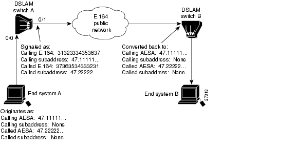
Figure 15-1 E.164 Gateway Conversion Example
The AESA address is used to initiate the call at the ingress to the public network. The public network routes the call based on the E.164 address. AESA subaddresses are carried through the public network in the subaddress fields. The AESA address is used to complete the call at the egress from the public network.
Note
Configuring an E.164 Address Static Route
To configure an E.164 address static route, use this command in global configuration mode:
Example
This example uses the atm route command to configure a static route using the 13-byte switch prefix 47.00918100000000410B0A1081 to ATM interface 0/0 with the E.164 address 1234567 and displays the result (To complete the E.164 address static route configuration, proceed to the "Configuring an ATM E.164 Address on an Interface" section):
DSLAM(config)# atm route 47.00918100000000410B0A1081 atm 0/0 e164-address 7654321DSLAM# show atm routeCodes: P - installing Protocol (S - Static, P - PNNI, R - Routing control),T - Type (I - Internal prefix, E - Exterior prefix, SE -Summary Exterior prefix, SI - Summary Internal prefix,ZE - Suppress Summary Exterior, ZI - Suppress Summary Internal)P T Node/Port St Lev Prefix~ ~~ ~~~~~~~~~~~~~~~~ ~~ ~~~ ~~~~~~~~~~~~~~~~~~~~~~~~~~~~~~~~~~~~~~~~~~~~~~~~~~~S E 1 ATM0/1 DN 0 47.0091.8100.0000.0001/72P SI 1 0 UP 0 47.0091.8100.0000.0002.eb1f.fe00/104R I 1 ATM0/0 UP 0 47.0091.8100.0000.0002.eb1f.fe00.0002.eb1f.fe00/152R I 1 ATM0/0 UP 0 47.0091.8100.0000.0002.eb1f.fe00.4000.0c/128P SI 1 0 UP 0 47.0091.8100.0000.0040.0b0a.2b81/104S E 1 ATM0/0 DN 0 47.0091.8100.0000.0040.0b0a.2b81/104(E164 Address 1234567)R I 1 ATM0/0 UP 0 47.0091.8100.0000.0040.0b0a.2b81.0040.0b0a.2b81/152R I 1 ATM0/0 UP 0 47.0091.8100.0000.0040.0b0a.2b81.4000.0c/128Configuring an ATM E.164 Address on an Interface
You can configure one E.164 address per ATM port. Signaling uses E.164 addresses in the called and calling party IEs, and uses AESA addresses in the called and calling party subaddress IEs.
To configure an E.164 address on a per-interface basis, perform these tasks, beginning in global configuration mode:
1.
interface atm slot/port
Select an interface port.
2.
atm e164 address e164-address
Associate the E.164 address to the interface.
Example
This example configures the E.164 address 7654321 on ATM interface 0/1 and displays the result:
DSLAM(config)# interface atm 0/1DSLAM(config-if)# atm e164 address 7654321DSLAM# show atm interface atm 0/1Interface: ATM0/1 Port-type: oc3suniIF Status: UP Admin Status: upAuto-config: enabled AutoCfgState: completedIF-Side: Network IF-type: NNIUni-type: not applicable Uni-version: not applicableMax-VPI-bits: 8 Max-VCI-bits: 14Max-VP: 255 Max-VC: 16383Svc Upc Intent: pass Signalling: EnabledATM Address for Soft VC: 47.0091.8100.0000.0041.0b0a.1081.4000.0c80.0010.00ATM E164 Address: 7654321Configured virtual links:PVCLs SoftVCLs SVCLs PVPLs SoftVPLs SVPLs Total-Cfgd Installed-Conns3 0 0 0 0 0 3 3Logical ports(VP-tunnels): 0Input cells: 226064 Output cells: 2261395 minute input rate: 0 bits/sec, 0 cells/sec5 minute output rate: 0 bits/sec, 0 cells/secInput AAL5 pkts: 147608, Output AAL5 pkts: 147636, AAL5 crc errors: 0When the E.164 gateway feature is configured, the DSLAM first attempts to make a connection using the E.164 gateway feature. If that connection fails, the DSLAM attempts to make the connection using the E.164 address autoconversion feature. Proceed to the next section for configuration instructions.
Configuring E.164 Address Autoconversion
If your network uses E164_ZDSP or E164_AESA addresses, you can configure E.164 address autoconversion. The E164_ZDSP and E164_AESA addresses include an embedded E.164 number in the E.164 portion of an E.164 ATM address. This embedded E.164 number is used in the autoconversion process.
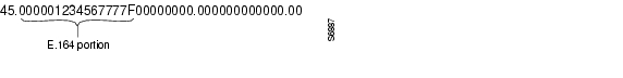
The E.164 portion of an E.164 ATM address is the first 15 digits following the authority and format identifier (AFI) of 45, shown in Figure 15-2.
Figure 15-2 E.164 Portion of an E.164 ATM Address
The E.164 portion is right-justified and ends with an "F." If all fifteen digits are not being used, the unused digits are filled with zeroes. In Figure 15-2, the embedded E.164 number is 1234567777, but it is signaled at the egress of the DSLAM and in the E.164 public network as 31323334353637373737.
The autoconversion process differs slightly between the E164_ZDSP and E164_AESA address formats. Table 15-1 compares the E.164 address autoconversion process by address type. The main difference between the two types is the way the IEs are signaled at the egress of the DSLAM, as described in the second row of Table 15-1. Note that during the final conversion process, the calling AESA and called AESA return to their original values.
Figure 15-3 shows an example of an E164_ZDSP address autoconversion.
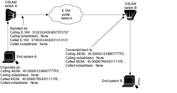
Figure 15-3 E164_ZDSP Sample Address Autoconversion
In Figure 15-3, a call (connection) from end system A is placed to end system B on the other side of an E.164 public network. The call originates as an E.164 ATM address and is signaled in native E.164 format at the egress port of DSLAM switch A and within the E.164 public network. When the call reaches the ingress port of DSLAM switch B, at the edge of the E.164 public network, the call is converted back to E.164 ATM address format.
Note
Figure 15-4 shows an example of an E164_AESA address autoconversion.
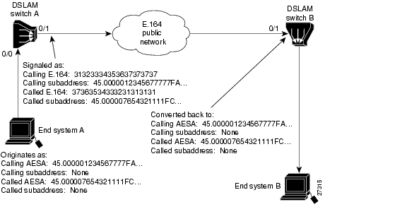
Figure 15-4 E164_AESA Address Autoconversion Example
In Figure 15-4, a call from end system A is placed to end system B on the other side of an E.164 public network. The call originates as an E.164 ATM address and at the egress port of DSLAM switch A and within the E.164 public network:
•
•
•
When the call reaches the ingress port of DSLAM switch B, at the edge of the E.164 public network, the call is converted back to E.164 ATM address format and:
•
•
•
Note
E.164 address autoconversion configuration is the same, regardless of which type of address (E164_ZDSP or E164_AESA) your network uses. To configure E.164 address autoconversion, perform these steps, beginning in global configuration mode:
Examples
DSLAM(config)# atm route 45.000007654321111F atm 0/1DSLAM(config)# int atm 0/1DSLAM(config-if)# atm e164 auto-conversionConfigure interface 0/1 of DSLAM switch A in the example networks shown in Figure 15-3 and Figure 15-4.
DSLAM(config)# atm route 45.000001234567777F atm 0/1DSLAM(config)# int atm 0/1DSLAM(config-if)# atm e164 auto-conversionConfigure interface 0/1 of DSLAM switch B.
DSLAM# show atm interface atm 0/1Interface: ATM0/1 Port-type: oc3suniIF Status: DOWN Admin Status: downAuto-config: disabled AutoCfgState: not applicableIF-Side: Network IF-type: UNIUni-type: Private Uni-version: V3.0Max-VPI-bits: 8 Max-VCI-bits: 14Max-VP: 255 Max-VC: 16383ConfMaxSvpcVpi: 255 CurrMaxSvpcVpi: 255ConfMaxSvccVpi: 255 CurrMaxSvccVpi: 255ConfMinSvccVci: 33 CurrMinSvccVci: 33Svc Upc Intent: pass Signalling: EnabledATM Address for Soft VC: 47.0091.8100.0000.0002.eb1f.fe00.4000.0c80.0010.00ATM E164 Auto Conversion InterfaceConfigured virtual links:PVCLs SoftVCLs SVCLs TVCLs PVPLs SoftVPLs SVPLs Total-Cfgd Inst-Conns2 0 0 0 0 0 0 2 0Logical ports(VP-tunnels): 0Input cells: 0 Output cells: 05 minute input rate: 0 bits/sec, 0 cells/sec5 minute output rate: 0 bits/sec, 0 cells/secInput AAL5 pkts: 0, Output AAL5 pkts: 0, AAL5 crc errors: 0Display the E.164 configuration for ATM interface 0/1.
Configuring E.164 Address One-to-One Translation Table
The ATM interface to a public network commonly uses an E.164 address for ATM signaling, with ARB_AESA addresses carried in the subaddress fields of the message.
Caution
The one-to-one translation table allows signaling to look up the E.164 addresses and the ARB_AESA addresses in a database, allowing a one-to-one correspondence between ARB_AESA addresses and E.164 addresses.
During egress operation, when a signaling message attempts to establish a call out an interface, the called and calling party addresses are in ARB_AESA format.
If the interface has been configured for E.164 translation, signaling attempts to find a match for the ARB_AESA addresses. If found, the E.164 addresses corresponding to the ARB_AESA addresses are placed into the called and calling party addresses. The original ARB_AESA addresses are also placed into the called and calling party subaddresses.
•
•
•
•
To configure a one-to-one E.164 translation table:
Step 1
Step 2
Step 3
To configure E.164 translation on the interface, perform these steps, beginning in global configuration mode:
1.
interface atm slot/port
Select an interface port.
2.
atm e164 translation
Configure the ATM E.164 interface.
3.
exit
Return to EXEC configuration mode.
4.
atm e164 translation-table
Change to E.164 ATM configuration mode.
5.
e164 address address nsap-address1 nsap_address
Configure the E.164 translation table.
1 The NSAP address is the same as the ARB_AESA address.
Examples
This example shows how to configure the ATM interface 0/1 to use the one-to-one E.164 translation table:
DSLAM(config)# interface atm 0/1DSLAM(config-if)# atm e164 translationDSLAM(config-if)# exitDSLAM(config)# atm e164 translation-tableDSLAM(config-atm-e164)# e164 address 1111111 nsap-address 11.111111111111111111111111.112233445566.11DSLAM(config-atm-e164)# e164 address 2222222 nsap-address 22.222222222222222222222222.112233445566.22DSLAM(config-atm-e164)# e164 address 3333333 nsap-address 33.333333333333333333333333.112233445566.33These commands:
1.
2.
3.
4.
5.
6.
7.
This example shows how to display the E.164 translation table configuration:
DSLAM# show running-configBuilding configuration...Current configuration:!version XX.Xno service padservice udp-small-serversservice tcp-small-servers!hostname DSLAM!!username dtate!atm e164 translation-tablee164 address 1111111 nsap-address 11.111111111111111111111111.112233445566.11e164 address 2222222 nsap-address 22.222222222222222222222222.112233445566.22e164 address 3333333 nsap-address 33.333333333333333333333333.112233445566.33!atm service-category-limit cbr 64544atm service-category-limit vbr-rt 64544atm service-category-limit vbr-nrt 64544atm service-category-limit ubr 64544atm address 47.0091.8100.0000.0040.0b0a.2b81.0040.0b0a.2b81.00--More--<information deleted>This example shows how to display the E.164 configuration for ATM interface 0/1:
DSLAM# show atm interface atm 0/1Interface: ATM0/1 Port-type: oc3suniIF Status: DOWN Admin Status: administratively downAuto-config: enabled AutoCfgState: waiting for response from peerIF-Side: Network IF-type: UNIUni-type: Private Uni-version: V3.0Max-VPI-bits: 8 Max-VCI-bits: 14Max-VP: 255 Max-VC: 16383Svc Upc Intent: pass Signalling: EnabledATM Address for Soft VC: 47.9999.9999.0000.0000.0000.0216.4000.0c80.0010.00ATM E164 Translation InterfaceConfigured virtual links:PVCLs SoftVCLs SVCLs PVPLs SoftVPLs SVPLs Total-Cfgd Installed-Conns2 0 0 0 0 0 2 0Logical ports(VP-tunnels): 0Input cells: 0 Output cells: 05 minute input rate: 0 bits/sec, 0 cells/sec5 minute output rate: 0 bits/sec, 0 cells/secInput AAL5 pkts: 0, Output AAL5 pkts: 0, AAL5 crc errors: 0Configuring Signaling Diagnostics Tables
Use signaling diagnostics to diagnose a specific call failure in your network and pinpoint the location of the call failure along with the reason for the failure.
To do this, you must:
1.
2.
3.
Note
To configure the signaling diagnostics table entries, perform these tasks, beginning in global configuration mode:
1.
atm signalling diagnostics enable
Enable ATM signaling diagnostics
2.
atm signalling diagnostics index
Change to ATM signaling diagnostics configuration mode.
3.
age-timer seconds
Configure the timeout value for the entry, in seconds.
4.
calling-address-mask nsap_address_mask2
Configure a filtering criteria based on the calling address mask value to be used to identify the valid bits of the calling NSAP address of the rejected call.
5.
called-nsap-address nsap_addrress
Configure a filtering criteria based on the called NSAP address of the rejected call.
6.
called-address-mask nsap_address_mask1
Configure a filtering criteria based on the called address mask value used to identify the valid bits of the calling NSAP address of the rejected call.
7.
calling-nsap-address nsap_address
Configure a filtering criteria based on the calling NSAP address of the rejected call.
8.
cast-type {p2p | p2mp | all}
Configure a filtering criteria based on the cast type of the rejected call. (The default is all.)
9.
clear-cause number2
Configure a filtering criteria based on the cleared cause code of the rejected call.
10.
connection-category {soft-vc | soft-vp | reg-vc | all}
Configure a filtering criteria based on the VC connection category of the rejected call.
11.
incoming-port atm slot/port
Configure a filtering criteria based on the incoming port of the rejected call.
12.
max-records number
Configure the maximum number of entries to be stored in the display table for each of the entries in the filter table.
13.
outgoing-port atm slot/port
Configure a filtering criteria based on the outgoing port of the rejected call.
14.
purge
Purge all the filtered records in the filter table.
15.
scope {internal | external}
Configure a filtering criteria based on the scope of the rejected call which either failed internally in the DSLAM or externally on other DSLAMs or switches.
16.
service-category {cbr | vbr-rt | vbr-nrt | ubr | all}
Configure a filtering criteria based on the service category of the rejected call.
17.
status [active filter_criteria | inactive filter_criteria | delete filter_criteria]
Configure the status of the entry in the filter table.
1 The combination of the configured calling_addr_mask (called_address_mask) and the configured calling_nsap_address (called_nsap_address) are used to filter the rejected call.
2 You can obtain the cause code values from the ATM forum UNI 3.1 specification.
The display table contains the records that were collected based on every filtering criteria in the filter table. Each filtering criteria has only a specified number of records that are stored in the table. After that specified number of records is exceeded, the table is overwritten.
Examples
Configuring Closed User Group Signaling Overview
You can configure a closed user group (CUG) to form restricted access groups (virtual private networks). You can define different CUGs and a specific user can be a member of one or more CUGs. Members of a CUG can communicate among themselves, but not with users outside the group. Specific users can have additional restrictions that prevent them from originating or receiving calls from other members of the CUG. You can also specify additional restrictions on originating and receiving calls to or from members of other CUGs.
For example, if you configure three CUGs (A, B, and C) in your network, you can configure them so that groups B and C can communicate with group A without restriction, but groups B and C cannot communicate between each other.You can also configure specific members of the same group to not accept calls from members of the same group.
The basis for CUGs are interlock codes. Interlock codes are:
•
•
At the network boundary where the call originates, when a call is received from the user, the DSLAM or switch generates the CUG IE and sends it as part of the SETUP message. In this software release, the CUG IE can only contain the preferential CUG's interlock code. The CUG IE is used at the destination network interface to determine if the call should be forwarded or rejected. The CUG IE is forwarded transparently by the intermediate DSLAMs or switches.
Note
Two types of interlock codes are defined:
•
•
Note
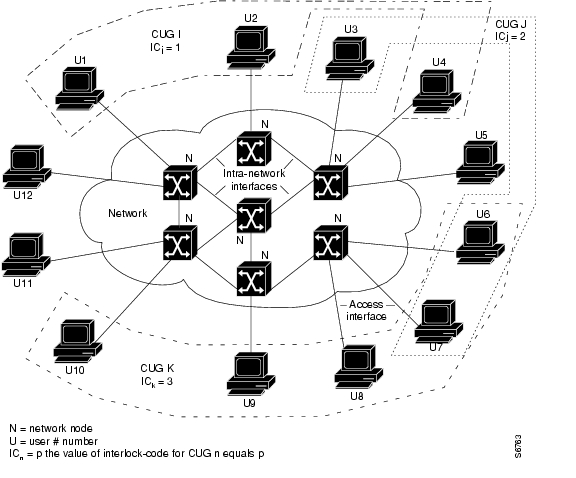
Figure 15-5 provides examples of CUGs and consists of these components:
•
•
•
•
•
Figure 15-5 Closed User Groups
Two CUG calls shown in Figure 15-5 are:
•
•
Configuring Aliases for CUG Interlock Code
You can define an alias for each CUG interlock code used on the DSLAM. Using an alias can simplify configuration of a CUG on multiple interfaces. When you use an alias, you no longer need to specify the 48-hexadecimal-digit CUG interlock code on each interface attached to a CUG member.
To configure an alias for a CUG interlock code, use this command in global configuration mode:
atm signalling cug alias alias_name interlock-code interlock_code
Configure the alias for the CUG interlock code.
Example
This example shows how to configure the alias TEST for the CUG interlock code 4700918100000000603E5A790100603E5A790100.12345678:
DSLAM(config)# atm signalling cug alias TEST interlock-code
4700918100000000603E5A790100603E5A790100.12345678
Configuring CUG on an Interface
This section describes how to configure CUG on interfaces.
To perform CUG configuration:
Step 1
Step 2
Note
Step 3
Note
For each CUG configured on the interface, you can specify that calls to or from other members of the same CUG be denied. In ITU-T terminology, this is called outgoing-calls-barred (OCB) and incoming-calls-barred (ICB), respectively.
Table 15-2 describes the relationship between the ITU-T CUG terminology and Cisco CUG terminology.
To configure an access interface and the CUG in which the interface is a member, perform these tasks, beginning in global configuration mode:
Example
This example shows how to configure an interface as a CUG access interface and assign a preferential CUG and displays the result:
DSLAM(config)# interface atm 0/1DSLAM(config-if)# atm signalling cug access permit-unknown-cugs both-direction permanentDSLAM(config-if)# atm signalling cug assign interlock-code 4700918100000000603E5A790100603E5A790100.12345678 preferentialTo display the global CUG configuration, use these EXEC commands:
Examples
To display the ATM signaling statistics, use the EXEC command:
Example
This example displays the ATM signaling statistics:
DSLAM# show atm signalling statisticsGlobal Statistics:Calls Throttled: 0Max Crankback: 3Max Connections Pending: 255Max Connections Pending Hi Water Mark: 1ATM 0/0:0 UP Time 01:06:20 # of int resets: 0----------------------------------------------------------------Terminating connections: 0 Soft VCs: 0Active Transit PTP SVC: 0 Active Transit MTP SVC: 0Port requests: 0 Source route requests: 0Conn-Pending: 0 Conn-Pending High Water Mark: 1Calls Throttled: 0 Max-Conn-Pending: 40Messages: Incoming Outgoing--------- -------- --------PTP Setup Messages: 0 0MTP Setup Messages: 0 0Release Messages: 0 0Restart Messages: 0 0Message: Received Transmitted Tx-Reject Rx-RejectAdd Party Messages: 0 0 0 0Failure Cause: Routing CAC Access-list Addr-Reg Misc-FailureLocation Local: 0 0 0 0 12334Location Remote: 0 0 0 0 0ATM 0/2:0 UP Time 3d21h # of int resets: 0----------------------------------------------------------------Terminating connections: 0 Soft VCs: 0Active Transit PTP SVC: 0 Active Transit MTP SVC: 0Port requests: 0 Source route requests: 0Conn-Pending: 0 Conn-Pending High Water Mark: 0Calls Throttled: 0 Max-Conn-Pending: 40<information deleted>Disabling Signaling on an Interface
If you disable signaling on a PNNI interface, PNNI routing is also disabled and ILMI is automatically restarted each time signaling is enabled or disabled.
To disable signaling on an interface, perform these tasks, beginning in global configuration mode:
1.
interface atm slot/port
Select the interface to be configured.
2.
no atm signalling enable
Disable signaling on the interface.
Example
This example shows how to disable signaling on ATM interface 0/1:
DSLAM(config)# interface atm 0/1DSLAM(config-if)# no atm signalling enableDSLAM(config-if)#%ATM-5-ATMSOFTSTART: Restarting ATM signalling and ILMI on ATM0/1.
![]()
![]()
![]()
![]()
![]()
![]()
![]()
![]()
Posted: Fri Dec 3 13:54:50 PST 2004
All contents are Copyright © 1992--2004 Cisco Systems, Inc. All rights reserved.
Important Notices and Privacy Statement.