|
|

Product Number: 6100/30-NI2-I/O-1(=)
This document provides information about installing and replacing the Cisco 6100/6130 with NI-2 system I/O card. The system I/O card is a field-replaceable unit (FRU) for the following chassis:
The system I/O card is installed on the chassis backplane.
This document includes the following sections:
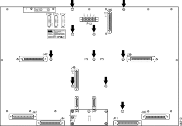
The system I/O card attaches to the two 2-mm HM card connectors, P3 and P9, on the chassis backplane. See Figure 1 for the system I/O card location on the Cisco 6100.
Figure 2 shows a close-up of the system I/O card.
Table 1 describes the connectors and headers on the system I/O card.
| 1Each wire-wrap header is connected to a relay contact on the active NI-2 card in the node chassis through the system I/O card connectors.
2AUD = audible. 3CRIT = critical. 4CO = common. 5NO = normally open. 6NC = normally closed. 7MAJ = major. 8MIN = minor. 9VIS = visual. 10The ACO button is located on the faceplate of the NI-2 card. This switch turns off the audible alarms that are generated by the system software. 11GND = ground. 12RX_BITS = receive building-integrated timing source. |
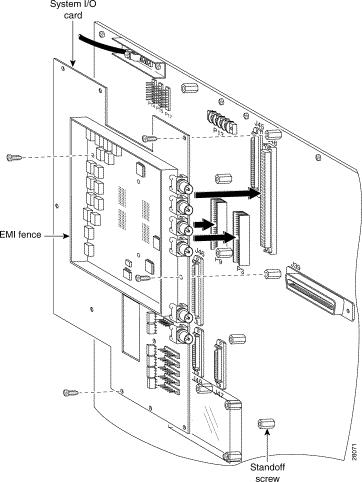
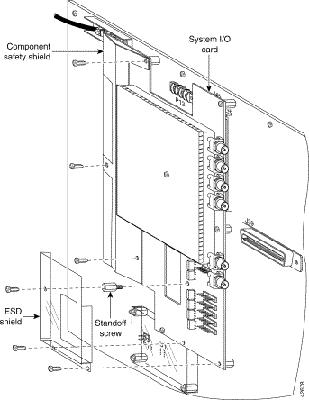
An EMI shield is formed by the EMI fence, which is soldered in place on the system I/O card, and the EMI cover (see Figure 2). Printed circuit board fuses, relays, and surge protectors are shielded by two clear plastic covers: a safety shield and an ESD shield. The EMI cover and protective shields must be in place during chassis with NI-2 system operation.
This section provides hardware and software requirements and a list of parts and tools that you need to install the system I/O card.
The system I/O card is installed on all backplanes, and it is not a stand-alone product. In order for a system I/O card to work properly you must also have an NI-2 network interface running on your Cisco 6100/6130.
Table 2 lists the Cisco IOS release recommended for use when you configure and manage the system I/O card for Cisco 6100/6130 with NI-2 systems.
| Hardware Platform | Recommended Minimum Cisco IOS Release |
|---|---|
The system I/O card is shipped with the Cisco 6100/6130 NI-2 system in a kit that includes the components listed in Table 3.
| Component Name | Quantity | Cisco Part Number | |
|---|---|---|---|
| Subassembly | Kit | ||
| 1The EMI fence is attached (soldered) to the system I/O card. |
You need the following parts and tools to install a system I/O card. If you need additional equipment, ask your service representative for ordering information.
This section provides safety and ESD-prevention guidelines. Use these guidelines to avoid injury and damage to the equipment during installation. Follow these safety guidelines when working with equipment that connects to electrical power or telephone wiring.
This section covers the following topics:
Before working on the equipment, be aware of standard safety practices and the hazards involved in working with electrical circuitry to prevent accidents. Adhere to the following cautions and warnings for safe and hazard-free installation.
 |
Note To see translations of the warnings that appear in this publication, refer to the Regulatory Compliance and Safety Information for the Cisco 6100/6130 System document. |
 |
Caution Proper ESD protection is required whenever you handle Cisco DSLAM equipment. Installation and maintenance personnel should be properly grounded using ground straps to eliminate the risk of ESD damage to the equipment. Modules are subject to ESD damage whenever they are removed from the chassis. |
|
Caution Be careful when you remove the standoff screws and reinsert the screws into the screw holes on the backplane so that the backplane circuitry does not become damaged. |
|
Caution If the modules are installed when you apply power to the system, you could damage the modules and the chassis. |
|
Caution If fuses are already installed in the fuse and alarm panel, remove them. You can replace the fuses after the system I/O card is installed. Do not power up the system while you install and connect the system I/O card. |
 |
Warning The customer 48 volt power system must provide reinforced insulation between the primary AC power and the 48 VDC output. |
|
Warning There is the danger of explosion if the battery is replaced incorrectly. Replace the battery only with the same or equivalent type recommended by the manufacturer. Dispose of used batteries according to the manufacturer's instructions. |
|
Warning Class 1 laser product. |
|
Warning Use copper conductors only. |
|
Warning A readily accessible two-poled disconnect device must be incorporated in the fixed wiring. |
|
Warning The DS3 ports are not intended to be connected to cables that run outside the building where it is installed. For any connections outside the building, the DS3 ports must be connected to a network termination unit (NTU). NTU devices should comply with appropriate national safety standards such as UL 1950, CSA 950, EN 60950, IEC 950, and AS 3260. |
|
Warning Do not reach into a vacant slot or chassis while you install or remove a module or a fan. Exposed circuitry could constitute an energy hazard. |
|
Warning Ethernet cables must be shielded when used in a central office environment. |
|
Warning An exposed wire lead from a DC-input power source can conduct harmful levels of electricity. Be sure that no exposed portion of the DC-input power source wire extends from the terminal block plug. |
|
Warning Incorrect connection of this or connected equipment to a general purpose outlet could result in a hazardous situation. |
|
Warning Read the installation instructions before you connect the system to its power source. |
|
Warning Only trained and qualified personnel should be allowed to install, replace, or service this equipment. |
|
Warning Do not work on the system or connect or disconnect cables during periods of lightning activity. |
|
Warning This unit has more than one power supply connection; all connections must be removed completely to completely remove power from the unit. |
|
Warning To reduce the risk of fire, use only No. 26 AWG or larger telecommunication line cord. |
|
Warning To prevent the system from overheating, do not operate it in an area that exceeds the maximum recommended ambient temperature of 104°F (40°C). |
|
Warning Secure all power cabling when installing this unit to avoid disturbing field-wiring connections. |
|
Warning The power supply circuitry for the equipment can constitute an energy hazard. Before you install or replace the equipment, remove all jewelry (including rings, necklaces, and watches). Metal objects can come into contact with exposed power supply wiring or circuitry inside the DSLAM equipment. This could cause the metal objects to heat up and cause serious burns or weld the metal object to the equipment. |
|
Warning Ultimate disposal of this product should be handled according to all national laws and regulations. |
|
Warning This unit is intended for installation in restricted access areas. A restricted access area is where access can only be gained by service personnel through the use of a special tool, lock and key, or other means of security, and is controlled by the authority responsible for the location. |
|
Warning Connect the unit only to DC power source that complies with the Safety Extra-Low Voltage (SELV) requirements in IEC 60950 based safety standards. |
|
Warning This product requires short-circuit (overcurrent) protection, to be provided as part of the building installation. Install only in accordance with national and local wiring regulations. |
|
Warning Care must be given to connecting units to the supply circuit so that wiring is not overloaded. |
|
Warning During this procedure, wear grounding wrist straps to avoid ESD damage to the card. Do not directly touch the backplane with your hand or any metal tool, or you could shock yourself. |
The following are examples of recommended installation and replacement practices:
Any card that is only partially connected to the backplane can disrupt system operation.
The Cisco 6100/6130 with NI-2 chassis should ship with the system I/O card already installed on the chassis backplane. The system I/O card is attached to chassis connectors P3 and P9, two 2-mm hard metric (HM) module connectors.
If the system I/O card is missing from the Cisco 6100/6130 with NI-2, complete the following steps to install it on the chassis backplane:
Step 2 Remove the fuses from the fuse and alarm panel. By removing the fuses, the system is not powered while you install and connect the system I/O card.
Step 3 Locate the twelve backplane screws shown in Figure 3. Use a Phillips-head screwdriver to remove the backplane screws. Keep these backplane screws for use when you install the system I/O card.
Step 4 Use a 1/4 inch socket driver or wrench to screw ten standoff screws into the locations formerly occupied by ten of the twelve screws that you removed in Step 1. Tighten the standoff screws using the 1/4 inch socket driver or wrench. See Figure 4 for standoff screw location.
|
Caution Be careful not to damage backplane circuitry when you remove and reinsert the standoff screws on the backplane. |
Step 5 Hold the system I/O card vertically and align the holes on the system I/O card over the twelve standoff screws, as shown in Figure 5.
Step 6 Carefully press the system I/O card onto the Cisco 6100/6130 with NI-2 connectors P3 and P9 on the chassis backplane until the system I/O card is in place and against the standoff screws.
Step 7 Use a Phillips-head screwdriver and four backplane screws to attach the system I/O card to the standoff screws, as shown in Figure 5.
Step 8 Use a Phillips-head screwdriver and two backplane screws to attach the EMI cover bracket, as shown in Figure 6.
Step 9 Attach the EMI cover on the EMI fence, as shown in Figure 6.
|
Caution Be careful not to bend the tabs on the EMI cover when you install the cover on the EMI fence. |
Step 10 Verify that no EMI cover tabs are outside the EMI fence.
Step 11 Use a Phillip-head screwdriver and a screw to attach the EMI cover to the EMI cover bracket, as shown in Figure 6.
Step 12 Use a Phillips-head screwdriver and three backplane screws to attach the safety shield to the left side of the system I/O card, as shown in Figure 7. The backplane screws will screw into the existing standoff screws on the backplane.
Step 13 Use a 1/4 inch socket driver or wrench to screw a standoff screw between relays K4 and K5, as shown in Figure 7. Tighten the standoff screws using the 1/4 inch socket driver or wrench.
Step 14 Place the ESD shield above the standoff screw that you installed in Step 10 so that the hole in the shield aligns with the standoff screw, as shown in Figure 7.
Step 15 Use a Phillips-head screwdriver and three backplane screws to attach the plastic ESD shield to the system I/O card (see Figure 7).
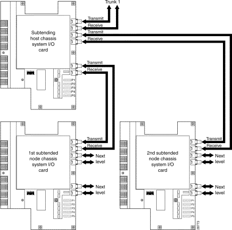
Coaxial connections for DS3 cabling are located on the system I/O card. The transmit and receive DS3 BNC connectors on the subtending host chassis system I/O card are connected to the transmit and receive DS3 BNC connectors on the subtended node chassis system I/O card.
|
Note The system I/O card BNC cables are not provided by Cisco. |
Complete the following steps to cable the system I/O card for subtending:
Step 2 On the first subtended node chassis backplane, attach the end of the BNC cable used in Step 1 to the receive DS3 BNC connector (J12) on the system I/O card.
Step 3 On the subtending host chassis backplane, attach one end of a BNC cable to the receive DS3 BNC connector (J8) on the system I/O card.
Step 4 On the first subtended node chassis backplane, attach the end of the BNC cable used in Step 3 to the transmit DS3 BNC connector (J14) on the system I/O card.
Step 5 On the subtending host chassis backplane, attach one end of a BNC cable to the transmit DS3 BNC connector (J6) on the system I/O card.
Step 6 On the second subtended node chassis backplane, attach the end of the BNC cable used in Step 5 to the receive DS3 BNC connector (J12) on the system I/O card.
Step 7 On the subtending host chassis backplane, attach one end of a BNC cable to the receive DS3 BNC connector (J4) on the system I/O card.
Step 8 On the second subtended node chassis backplane, attach the end of the BNC cable used in Step 7 to the transmit DS3 BNC connector (J14) on the system I/O card.
Figure 8 shows the cabling for a DS3 subtending network configuration.
Step 9 Close the optional rear cover, as necessary.
Step 10 Reinstall the fuse and alarm panel fuses.
The following sections provide information on removing and replacing the system I/O card.
See the following instructions to remove the system I/O card.
|
Caution Static voltages as low as 30 volts can cause latent damage to circuitry on the system I/O card. Be sure to observe all standard antistatic procedures (for example, wear a grounding strap). |
Step 2 Remove the fuses from the fuse and alarm panel. By removing the fuses, the system is not powered while you install and connect the system I/O card.
Step 3 If they are present, mark and disconnect all BNC coaxial cables at system I/O card receptacles J4, J6, J8, J10, J12, and J14.
Step 4 If they are present, mark and disconnect all wires at the system I/O card wire-wrap header pins.
Step 5 Remove the screw at the center of the EMI cover.
Step 6 Remove the EMI cover.
Step 7 Remove the two EMI cover bracket screws and the EMI cover bracket. (See Figure 9.)
Step 8 Remove the six screws at the center of the system I/O card ESD shield, and also remove the component safety shield and the ESD shield. (See Figure 10.)
Step 9 Remove the standoff screw from which the ESD shield screw was removed.
Step 10 Use a Phillips-head screwdriver to remove the four screws shown in Figure 11.
Step 11 Carefully pull the system I/O card away from connectors P3 and P9.
Step 12 Place the system I/O card in an antistatic bag or in a box lined with antistatic material.
Step 13 Store removed screws, covers, and shields in a safe place for reinstallation.
To reinstall the system I/O card, perform the following steps.
|
Caution Static voltages as low as 30 volts can cause latent damage to circuitry on the system I/O card. Be sure to observe all standard antistatic procedures (for example, wear a grounding strap). |
Step 2 Locate the previously removed system I/O card screws, covers, and shields.
Step 3 Check that you have installed a standoff screw at each of the chassis backplane standoff positions, as shown in Figure 12. Replace any missing standoffs with socket driver or wrench and check that all standoffs are tight.
|
Caution Do not overtighten the standoff screws. Overtightening can cause the system I/O card printed circuit board to crack. |
|
Caution Be careful not to damage backplane circuitry when you remove and reinsert the standoff screws on the backplane. |
Step 4 Hold the system I/O card vertically and align the holes on the system I/O card over the twelve standoff screws, as shown in Figure 13.
Step 5 Carefully press the system I/O card onto the Cisco 6100/6130 with NI-2 connectors P3 and P9 on the chassis backplane until the system I/O card is in place and against the standoff screws.
Step 6 Use a Phillips-head screwdriver and four backplane screws to attach the system I/O card to the standoff screws, as shown in Figure 13.
Step 7 Use a Phillips-head screwdriver and two backplane screws to attach the EMI cover bracket, as shown in Figure 14.
Step 8 Attach the EMI cover on the EMI fence, as shown in Figure 14.
|
Caution Be careful not to bend the tabs on the EMI cover when you install the cover on the EMI fence. |
Step 9 Verify that no EMI cover tabs are outside the EMI fence.
Step 10 Use a Phillip-head screwdriver and a screw to attach the EMI cover to the EMI cover bracket, as shown in Figure 14.
Step 11 Use a Phillips-head screwdriver and three backplane screws to attach the safety shield to the left side of the system I/O card, as shown in Figure 15. The backplane screws will screw into the existing standoff screws on the backplane.
Step 12 Use a 1/4 inch socket driver or wrench to screw a standoff screw between relays K4 and K5, as shown in Figure 15. Tighten the standoff screws using the 1/4 inch socket driver or wrench.
Step 13 Place the ESD shield above the standoff screw that you installed in Step 10 so that the hole in the shield aligns with the standoff screw, as shown in Figure 15.
Step 14 Use a Phillips-head screwdriver and three backplane screws to attach the plastic ESD shield to the system I/O card (see Figure 15).
Step 15 Reconnect the BNC connectors.
Step 16 Reconnect the wire-wrap headers.
Step 17 Reinsert the fuses in the fuse and alarm panel. When you reinsert the fuses, the system powers on.
Step 18 Cable for the DS3 subtending host configuration. See the "Cabling the DS3 Subtending Network Configuration" section for instructions.
Step 19 Close the rear cover.
A complete list of all DSL product related documentation is available on the World Wide Web at
http://www.cisco.com/univercd/cc/td/doc/product/dsl_prod/index.htm.
The following sections provide sources for obtaining documentation from Cisco Systems.
You can access the most current Cisco documentation on the World Wide Web at http://www.cisco.com, http://www-china.cisco.com, or http://www-europe.cisco.com.
Cisco documentation and additional literature are available in a CD-ROM package, which ships with your product. The Documentation CD-ROM is updated monthly. Therefore, it is probably more current than printed documentation. The CD-ROM package is available as a single unit or as an annual subscription.
Registered CCO users can order the Documentation CD-ROM and other Cisco Product documentation through our online Subscription Services at http://www.cisco.com/cgi-bin/subcat/kaojump.cgi.
Nonregistered CCO users can order documentation through a local account representative by calling Cisco's corporate headquarters (California, USA) at 408 526-4000 or, in North America, call 800 553-NETS (6387).
Cisco provides Cisco Connection Online (CCO) as a starting point for all technical assistance. Warranty or maintenance contract customers can use the Technical Assistance Center. All customers can submit technical feedback on Cisco documentation using the web, e-mail, a self-addressed stamped response card included in many printed docs, or by sending mail to Cisco.
Cisco continues to revolutionize how business is done on the Internet. Cisco Connection Online is the foundation of a suite of interactive, networked services that provides immediate, open access to Cisco information and resources at anytime, from anywhere in the world. This highly integrated Internet application is a powerful, easy-to-use tool for doing business with Cisco.
CCO's broad range of features and services helps customers and partners to streamline business processes and improve productivity. Through CCO, you will find information about Cisco and our networking solutions, services, and programs. In addition, you can resolve technical issues with online support services, download and test software packages, and order Cisco learning materials and merchandise. Valuable online skill assessment, training, and certification programs are also available.
Customers and partners can self-register on CCO to obtain additional personalized information and services. Registered users may order products, check on the status of an order and view benefits specific to their relationships with Cisco.
You can access CCO in the following ways:
You can e-mail questions about using CCO to cco-team@cisco.com.
The Cisco Technical Assistance Center (TAC) is available to warranty or maintenance contract customers who need technical assistance with a Cisco product that is under warranty or covered by a maintenance contract.
To display the TAC web site that includes links to technical support information and software upgrades and for requesting TAC support, use www.cisco.com/techsupport.
To contact by e-mail, use one of the following:
| Language | E-mail Address |
|---|---|
In North America, TAC can be reached at 800 553-2447 or 408 526-7209. For other telephone numbers and TAC e-mail addresses worldwide, consult the following web site: http://www.cisco.com/warp/public/687/Directory/DirTAC.shtml.
If you are reading Cisco product documentation on the World Wide Web, you can submit technical comments electronically. Click Feedback in the toolbar and select Documentation. After you complete the form, click Submit to send it to Cisco.
You can e-mail your comments to bug-doc@cisco.com.
To submit your comments by mail, for your convenience many documents contain a response card behind the front cover. Otherwise, you can mail your comments to the following address:
Cisco Systems, Inc.
Document Resource Connection
170 West Tasman Drive
San Jose, CA 95134-9883
We appreciate and value your comments.
CCIP, the Cisco Arrow logo, the Cisco Powered Network mark, the Cisco Systems Verified logo, Cisco Unity, Follow Me Browsing, FormShare, iQ Breakthrough, iQ Expertise, iQ FastTrack, the iQ Logo, iQ Net Readiness Scorecard, Networking Academy, ScriptShare, SMARTnet, TransPath, and Voice LAN are trademarks of Cisco Systems, Inc.; Changing the Way We Work, Live, Play, and Learn, Discover All That's Possible, The Fastest Way to Increase Your Internet Quotient, and iQuick Study are service marks of Cisco Systems, Inc.; and Aironet, ASIST, BPX, Catalyst, CCDA, CCDP, CCIE, CCNA, CCNP, Cisco, the Cisco Certified Internetwork Expert logo, Cisco IOS, the Cisco IOS logo, Cisco Press, Cisco Systems, Cisco Systems Capital, the Cisco Systems logo, Empowering the Internet Generation, Enterprise/Solver, EtherChannel, EtherSwitch, Fast Step, GigaStack, Internet Quotient, IOS, IP/TV, LightStream, MGX, MICA, the Networkers logo, Network Registrar, Packet, PIX, Post-Routing, Pre-Routing, RateMUX, Registrar, SlideCast, StrataView Plus, Stratm, SwitchProbe, TeleRouter, and VCO are registered trademarks of Cisco Systems, Inc. and/or its affiliates in the U.S. and certain other countries.
All other trademarks mentioned in this document or Web site are the property of their respective owners. The use of the word partner does not imply a partnership relationship between Cisco and any other company. (0208R)
Copyright © 2003, Cisco Systems, Inc.
All rights reserved.
![]()
![]()
![]()
![]()
![]()
![]()
![]()
![]()
Posted: Tue Jan 28 06:20:06 PST 2003
All contents are Copyright © 1992--2002 Cisco Systems, Inc. All rights reserved.
Important Notices and Privacy Statement.