|
|

July 30, 1999
These release notes present information for assuring that your Cisco 6100 system is Network Equipment Building Systems (NEBS) compliant.
For more detailed information about the information in these release notes, refer to the "Related Documentation" section. Information about electronic documentation can be found in the "Cisco Connection Online" section, and in the "Documentation CD-ROM" section.
 | Caution Proper electrostatic discharge (ESD) protection is required whenever you handle Cisco DSLAM equipment. Installation and maintenance personnel should be properly grounded using ground straps to eliminate the risk of ESD damage to the equipment. Modules are subject to ESD damage whenever they are removed from the chassis. |
These release notes discuss the following topics:
For NEBS compliance, it is necessary to add ferrites to the cables used to connect
 | Caution If fuses are already installed in the fuse and alarm panel, remove them. You can replace the fuses after the system is cabled. The system should not be powered while adding the ferrites to the DS3 system I/O card, DS3 subtending card, and power connection cables. |
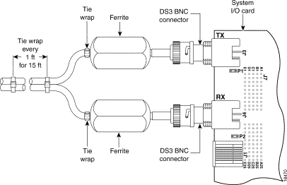
Use the following procedures to add ferrites to the DS3 system I/O card on the backplane of the MC. Figure 1 shows the attachment of the ferrites.
Step 2 Attach coax cables to the two DS3 BNC connectors (J3 and J4) on the left side of the DS3 system I/O card.
Step 3 Attach one ferrite (36-0087-01, quantity 2) to each of the cables as close to the DS3 BNC connectors as possible.
Step 4 Place one tie wrap (51-202060, quantity 18) directly behind each ferrite.
Step 5 Place another tie wrap around both cables where the cables meet after coming from the ferrite, and every 1 foot thereafter for a total of 15 feet.
Step 6 Reinsert the fuses in the fuse and alarm panel. By reinserting the fuses, the system will become powered.
If you have a subtended network, use the following procedures to add ferrites to the DS3 subtending card on the backplane of the MC. Figure 2 shows the attachment of the ferrites.
Step 2 Attach coax cables to the four DS3 BNC connectors (J1 through J4) on the right side of the DS3 subtending card.
Step 3 Attach one ferrite (36-0087-01, quantity 4) to each of the cables as close to the DS3 BNC connectors as possible.
Step 4 Place one tie wrap (51-202060, quantity 36) directly behind each ferrite.
Step 5 Place another tie wrap around both cables where the cables meet after coming from the ferrite, and every 1 foot thereafter for a total of 15 feet.
Step 6 Reinsert the fuses in the fuse and alarm panel. By reinserting the fuses, the system will become powered.

The power connections from the MC to the fuse and alarm panel can be wired for dual- or single-power feed.
The ferrites included in the NEBS compliance kit must be installed on the cables used to connect the fuse and alarm panel and the power connections on the MC. The cables used to connect the fuse and alarm panel and the power connections should be looped through the ferrite as shown in Figure 3.

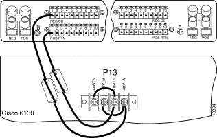
Use the following procedures to add ferrites to the cables connecting the power connections on the backplane of the MC to the fuse and alarm panel for dual-power feed. Figure 4 shows the dual-power feed connections from the MC to the fuse and alarm panel and the attachment of the ferrites to the power connection cables.
Step 2 Wire the -48V_A and -48V_B power connections from the MC (P13) to the fuse and alarm panel NEG DC connectors.
Step 3 Wire both -48RTN power connections from the MC (P13) to the fuse and alarm panel POS RTN connectors.
Step 4 Attach one ferrite (36-0087-01, quantity 4) close to the connectors on each of the cables going to the fuse and alarm panel.
Step 5 Reinsert the fuses in the fuse and alarm panel. By reinserting the fuses, the system will become powered.

Use the following procedures to add ferrites to the cables connecting the power connections on the backplane of the MC to the fuse and alarm panel for single-power feed. Figure 5 shows the dual-power feed connections from the MC to the fuse and alarm panel and the attachment of the ferrites to the power connection cables.
Step 2 Wire the -48V_B power connection from the MC (P13) to the fuse and alarm panel NEG DC connector.
Step 3 Wire a -48RTN power connection from the MC (P13) to the fuse and alarm panel POS RTN connector. See Figure 5 for correct placement.
Step 4 Wire the -48RTNs to each other.
Step 5 Wire the -48V_A and -48V_B to each other.
Step 6 Attach one ferrite (36-0087-01, quantity 4) close to the connectors on each of the cables going to the fuse and alarm panel.
Step 7 Reinsert the fuses in the fuse and alarm panel. By reinserting the fuses, the system will become powered.
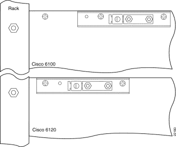
In the upper left corners of the MC and POTS splitter chassis (PSC) are ground lugs used to ground the chassis to the rack. The one hole lugs should be replaced by two hole lugs and a longer bracket. Figure 6 shows the original ground lugs.
 | Caution If fuses are already installed in the fuse and alarm panel, remove them. You can replace the fuses after you have replaced the ground lugs. The system should not be powered while replacing the ground lugs. |

Figure 7 shows the replacement ground lugs on both chassis
Use the following procedures to replace the ground lugs on the MC.
Step 2 Remove the original ground lug by removing the one screw and lug.
Step 3 Attach the new, longer bracket (700-04424-01) using both original screws. These screws should be in the second and third holes from the upper left corner of the MC.
Step 4 Attach the two hole lug (32-0621-01) to the adapter bracket using the two nuts (49-0401-01).
Step 5 Reinsert the fuses in the fuse and alarm panel. By reinserting the fuses, the system will become powered.
Use the following procedures to replace the ground lugs on the PSC.
Step 2 Remove the original ground lug by removing the one screw and lug.
Step 3 Attach the new, longer bracket (700-04424-01) using both original screws. These screws should be in the first and second holes from the upper left corner of the PSC.
Step 4 Attach the two hole lug (32-0621-01) to the adapter bracket using the two nuts (49-0401-01).
Step 5 Reinsert the fuses in the fuse and alarm panel. By reinserting the fuses, the system will become powered.
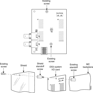
A plastic ESD shield should be mounted over the DS3 system I/O card. Use the following procedures to add the ESD shield. Figure 8 shows the addition of the ESD shield.
 | Caution If fuses are already installed in the fuse and alarm panel, remove them. You can replace the fuses after you have mounted the ESD shield over the DS3 system I/O card. The system should not be powered while mounting the ESD shield. |
Step 2 Remove the two screws holding the DS3 system I/O card to the two existing standoff screws attached to the backplane of the MC. Be careful that the card does not fall away from the connectors.
Step 3 Add additional standoff screws (50-0767-01) by screwing them through each of the screw holes in the DS3 system I/O card and into the original standoff screws.
Step 4 Position the holes in the plastic ESD shield (700-04921-01) over the new standoff screws and use the original screws from Step 1 to attach the shield to the new standoff screws.
Step 5 Reinsert the fuses in the fuse and alarm panel. By reinserting the fuses, the system will become powered.
A thermal shield is required between the two shelves of the MC to meet NEBS compliance. Use the following procedures to place the thermal shield between the shelves. Figure 9 shows the placement of the thermal shield in the MC.
Step 2 Remove all the modules from the lower shelf on the left side of the MC.
Step 3 Insert the thermal shield (700-04630-01) in the space between the upper and lower shelves. The shield orientation should be with the notch in the back and offset to the right, knife edge toward the rear of the chassis, rounded edges away from the rear of the chassis, and the arrow on the shield up.
Step 4 Insert the right rear corner of the thermal shield first to create a gap. Continue to push the shield into the guide plates as far as possible.
Step 5 Use the second shield or a flat head screw driver to push the thermal shield in until it drops onto the lower module guides.
Step 6 Replace the modules in the lower shelf and reprovision.
Step 7 Repeat the steps above for the right side of the MC.

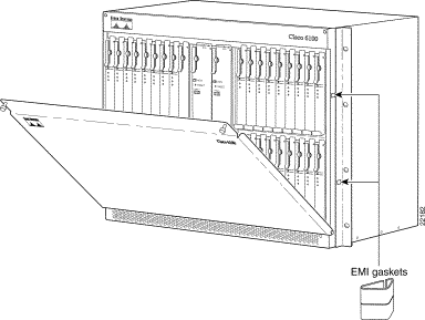
Use the following procedures to replace the front door of the MC chassis with a new stiffened door and EMI gaskets on the chassis. Figure 10 shows the replacement of the front door and the addition of the gaskets.
Step 2 Attach the new stiffened front door (700-03491-02) at the base of the lower shelf of the MC.
Step 3 Add two gaskets to either side of the chassis frame in the positions shown in the figure below.
Step 4 Use the screws in the upper corners of the door to close it firmly over the front of the chassis.
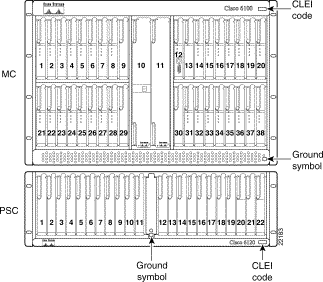
The grounding symbols, CLEI codes, and PSC 800 number labels should replace the current labels on the chassis. Figure 11 shows the positions of the labels being replaced.
Use the following steps to replace the proper labels on the MC.
Step 2 Replace the 800-04390-02 label on the right side of the chassis with the new 800-04390-03 label.
Step 3 Replace the original ground symbol label in the lower right corner of the MC with the new one.
Use the following steps to replace the proper labels on the PSC.
Step 2 Replace the 800-04325-03 label on the right side of the chassis with the new 800-04325-04 label.
Step 3 Replace the original ground symbol label in the lower center of the PSC with the new one.
Use these release notes in conjunction with the following documents:
Cisco Connection Online (CCO) is Cisco Systems' primary, real-time support channel. Maintenance customers and partners can self-register on CCO to obtain additional information and services.
Available 24 hours a day, 7 days a week, CCO provides a wealth of standard and value-added services to Cisco's customers and business partners. CCO services include product information, product documentation, software updates, release notes, technical tips, the Bug Navigator, configuration notes, brochures, descriptions of service offerings, and download access to public and authorized files.
CCO serves a wide variety of users through two interfaces that are updated and enhanced simultaneously: a character-based version and a multimedia version that resides on the World Wide Web (WWW). The character-based CCO supports Zmodem, Kermit, Xmodem, FTP, and Internet e-mail, and it is excellent for quick access to information over lower bandwidths. The WWW version of CCO provides richly formatted documents with photographs, figures, graphics, and video, as well as hyperlinks to related information.
You can access CCO in the following ways:
For a copy of CCO's Frequently Asked Questions (FAQ), contact cco-help@cisco.com. For additional information, contact cco-team@cisco.com.
Cisco documentation and additional literature are available in a CD-ROM package, which ships with your product. The Documentation CD-ROM, a member of the Cisco Connection Family, is updated monthly. Therefore, it might be more current than printed documentation. To order additional copies of the Documentation CD-ROM, contact your local sales representative or call customer service. The CD-ROM package is available as a single package or as an annual subscription. You can also access Cisco documentation on the World Wide Web at http://www.cisco.com, http://www-china.cisco.com, or http://www-europe.cisco.com.
If you are reading Cisco product documentation on the World Wide Web, you can submit comments electronically. Click Feedback in the toolbar and select Documentation. After you complete the form, click Submit to send it to Cisco. We appreciate your comments.
.
![]()
![]()
![]()
![]()
![]()
![]()
![]()
![]()
Posted: Thu Jul 25 00:52:46 PDT 2002
All contents are Copyright © 1992--2002 Cisco Systems, Inc. All rights reserved.
Important Notices and Privacy Statement.