|
|

This chapter describes how to use the web interface to manage the a Cisco CPE device.
The web interface is designed for individuals who prefer a GUI program or who are familiar with these navigational principles. The web interface enables you to set some configuration parameters in the browser, and to view other settings. The view-only functions are marked as "Display Only."
Microsoft Internet Explorer 2.0 the Cisco 67x web interface. You must use Netscape 4.0 or higher or Internet Explorer 4.0 or higher for the web interface.
 |
Note The web interface may not be available for certain Cisco CPE device configurations. Contact your service provider if you have questions concerning this feature. |
The user password comes in two modes: Exec (read-only), and Enable (both read and write). You must have Enable privileges to save changes made via the web interface to NVRAM.
Click Submit Changes and Write in the Configure menu to make changes to NVRAM.
 |
Caution The system disregards all changes when rebooted if you have not written the changes to NVRAM. |
Do the procedure below to activate the web interface.
Step 1 Logon to CBOS using either a serial or telnet interface.
Step 2 Enter the exec password.
Step 3 Enter the user name enable and press Enter to bypass the initial password if you have not yet created a password. If you have already created a password, proceed to Step 8.
 |
Note Your service provider may assign a user password. |
Step 4 On the CPE, set the address for the remote client. Enter:
set web remote n.n.n.nwhere n.n.n.n is the IP address of the remote client. For example:
set web remote 192.168.0.100 |
Note Only the remote client with that IP address will be able to access the CPE web interface. |
Step 5 To save the new configuration, enter:
cbos>writeStep 6 The web interface is enabled by default; however, if it was previously disabled, you must enable it with the following command:
cbos>set web enabledStep 7 Reboot the CPE.
Step 8 On the remote client, launch your preferred web browser.
Step 9 Enter the IP address assigned by your Cisco CPE service provider in the browser locator field. For example, instead of http//www.cisco.com/ insert the dotted decimal format (http://10.0.0.1/ ) of the Cisco 67x IP address. The following screen appears:
 |
Note Screens displayed here are representative of screens in the web interface. Screens for your particular Cisco 67x may vary slightly. |
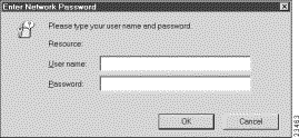
Step 10 Enter the user name and the password.
Step 11 Once the web interface home page appears, you should add a bookmark in your browser for the new Cisco 67x location. Once the bookmark has been added, simply activate the bookmark to access the web interface.
 |
Note If you have an exec-only password, you will not be able to make any changes to your configuration. |
When you start he Cisco web interface you first see the home page.
The web interface home page has four buttons that link to other pages. To navigate to the various pages, click the icon or on the appropriate word in the navigation line at the bottom of each page. The purpose of each of the pages is as follows:
Click Configure. Five sub buttons appear in the exec mode. A sixth button, the Write button, appears in the enable mode only.

The functions for each button are explained in the following sections.
The General button allows you to set general configuration parameters, such as the IP address and netmask of the Cisco 67x, the VC base and count metrics, and the DSL rate configuration. The three sections of the General Configuration screen and instructions on how to use these options are described below.
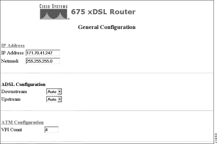
This option allows you to set the IP address and netmask for the Ethernet port of your Cisco equipment. Changing IP addresses will disconnect the web interface. You must reconnect using the new IP address.
To use this option:
Step 1 Enter the address and netmask (usually provided by LAN administrator or ISP).
Step 2 To apply these addresses, click Submit Changes.
Step 3 To reject these addresses, click Reset Values.
 |
Note Steps 2 and 3 appear in the enable mode only. |
Step 4 The new addresses are displayed.
This option allows you to set the up and downstream rates for your ADSL connection.
 |
Warning You should not need to change these values. To alter the values, consult your service provider. If these values are changed, you might lose the connection to your CPE. |
This option allows you to set up the total number of VPI addresses that you can configure.
To use this option:
Step 1 Select the Base and Count number from their respective drop down menus.
Step 2 To apply these numbers, click Submit Changes.
Step 3 To reject these numbers, click Reset Values.
Click Apps. The Application Configuration screen appears. Apps allows you to enable and disable applications associated with the Cisco 67x.
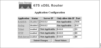
The applications are described in the following sections.
Remote Authentication Dial-In User Service (RADIUS), authenticates users for access to a network. The RADIUS server uses an authentication scheme, such as PAP, to authenticate incoming messages from RADIUS clients. When a password is present, it is hidden using a method based on the RSA Message Digest Algorithm MD5.
Select whether you want to enable or disable RADIUS via the first drop down menu.
Step 1 Specify the IP address of the server.
Step 2 Enter a port number.
Step 3 Click Submit Changes to apply changes or Reset Values to discard changes. These buttons are visible in the enable mode only.
Syslog logs system information to a specified Syslog server for processing without requiring large amounts of local storage or local processing.
Step 1 Select whether you want to enable or disable Syslog via the first drop down menu.
Step 2 Specify the IP address of the Syslog server.
Step 3 Enter a port number.
Step 4 Click Submit Changes to apply changes or Reset Values to discard changes. These buttons are visible in the enable mode only.
Telnet provides access to the CBOS command line interface via a network.
Step 1 Select whether you want to enable or disable Telnet via the first drop down menu.
Step 2 Specify the IP address of the machine allowed to use Telnet to connect to the Cisco 67x. To allow any machine to connect, specify 0.0.0.0.
Step 3 Enter a port number.
Step 4 Click Submit Changes to apply changes or Reset Values to discard changes. These buttons are visible in the enable mode only.
The Trivial File Transfer Protocol (TFTP) server allows you to transfer a new configuration file or new software to and from Cisco equipment.
Step 1 Select whether you want to enable or disable TFTP via the first drop down menu.
Step 2 Specify the IP address of the machine allowed to use TFTP to connect to the Cisco 67x. To allow any machine to connect, specify 0.0.0.0.
Step 3 Enter a port number.
Step 4 Click Submit Changes to apply changes or Reset Values to discard changes. These buttons are visible in the enable mode only.
The Web Server allows you to use the web interface to access Cisco equipment.
 |
Note The Web Server is enabled by default. |
Step 1 Select whether you want to enable or disable the web interface via the first drop down menu.
Step 2 Specify the IP address of the machine allowed to use the web interface to connect to the Cisco 67x. To allow any machine to connect, specify 0.0.0.0.
Step 3 Enter a port number.
Step 4 Click Submit Changes to apply changes or Reset Values to discard changes. These buttons are visible in the enable mode only.
 |
Note You write changes using the Write button under the configure menu before rebooting to apply changes. These changes take effect the next time you reboot the CPE. |
Click Filtering. The Filter Configuration screen appears. This option allows you to set up filters to prevent or allow the flow of IP packets into Cisco equipment.
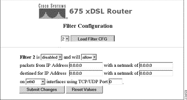
Step 1 Select the filter name and number from the first drop down menu at the top of the screen. Click Load Filter CFG to load existing filter information.
Step 2 Set filters by completing the sentence.
Step 3 Select either enabled or disabled from drop down menu to activate a filter.
Step 4 Select either allow or deny from the drop down menu. The allow option allows the specified filter to accept packets from a particular IP address. The deny option does not permit these packets to flow to a particular IP address.
Step 5 Enter the source address and netmask of where the packet is originating. The source address is the IP address of the source computer from which you will allow or deny traffic. The source netmask is the source network from which you will allow or deny traffic. By entering a source netmask, you can filter a group of incoming IP addresses.
Step 6 Enter the destination address and netmask. The destination address is the IP address of the computer that, if allowed, will receive packets originating from the source IP address. The destination netmask is the destination network that, if allowed, will receive packets originating from the source netmask. By entering a destination netmask, you can filter a group of outgoing IP addresses.
Step 7 Select the interface that this filter affects from the drop down menu. Select the all option for all interfaces.
Step 8 Select the TCP/UDP Port this affects from the drop down menu. Select 0 for all ports.
 |
Note You must click Submit Changes to save the routing changes to NVRAM. Also, once you change an IP address, you should reboot the Cisco 67x to bind the new IP addresses to the ports. |
Click Routing. The Routing Configuration screen appears. This option allows you to build a new routing table or change an existing routing table. Routes consist of the IP addresses of all machines with which you want to communicate, and the netmask, gateway, and precedence of those machines.
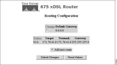
The Routing Configuration screen allows you to change your routing table. See the sections below for instructions on individual tasks.
Step 1 Left click in the Default Gateway box to select it.
Step 2 Click Submit Changes. A new screen appears that allows you to change the IP address of the default gateway. This button is visible in the enable mode only.
Step 3 Enter the IP address.
Step 4 To apply changes, click Submit Changes. To clear the changes, click Reset Values. These buttons are visible in the enable mode only.
Step 1 Select the route you want to change by clicking the button next to the route.
Step 2 Click Submit Changes. A new screen appears that allows you to change the route. This button is visible in the enable mode only.
Step 3 Enter the target address, the netmask, and the gateway.
Step 4 The target address is the IP address of the machine with which you are trying to communicate. You can modify or delete existing IP addresses by simply typing in the new address.
Step 5 The netmask is the address of the network with which you want to communicate. You can modify or delete existing netmask addresses by typing in the new address.
Step 6 The gateway is the address of the gateway machine through which the information you are sending is routed. Data is sent through the external gateway to the destination address. Therefore, this address must be the address of a gateway that is physically linked to your network. You can modify or delete existing gateway addresses by simply typing in the new address.
Step 7 Select the route Precedence. If no value is selected, the default precedence is set to 0.
Step 8 To apply changes, click Submit Changes. To clear the changes, click Reset Values. These buttons are visible in the enable mode only.
Step 9 The new routing information is displayed.
 |
Note Precedence routing routes data according to the precedence settings. The default setting is 0. |
Step 1 Click Add new route option.
Step 2 Click Submit Changes. A new screen appears.
Step 3 Enter the new route including the target IP address, the netmask, the gateway, and the precedence. See the section above for further descriptions on these addresses.
Step 4 To apply changes, click Submit Changes. To clear the changes, click Reset Values. These buttons are visible in the enable mode only.
Click User CFG. The User Configuration screen appears. This option allows you to set up a user profile for each logical WAN connection. The user profile can be saved and reloaded each time you want to reuse it.
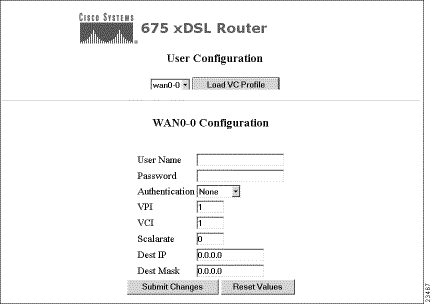
Step 1 Select the Virtual Circuit (VC) from the drop down menu.
Step 2 Click Load VC Profile.
Step 3 Enter or change existing user information. The field definitions are:
 |
Note User information is usually assigned and entered by your network administrator or service provider. |
Step 4 To submit changes, click Submit Changes. To undo all changes, click Reset Values. These buttons are visible in the enable mode only.
After you apply changes, the new user configuration information is displayed.
The Statistics button allows you to display statistics about applications, errors, and ports. The Statistics button has three sub-buttons shown below.

Click Apps. The Application Statistics screen appears. This screen displays the application statistics for the Cisco 67x. Click Load Statistics.

Click Errors. The following screen appears. This screen displays the current error report. Up to 40 errors at a time can be displayed.
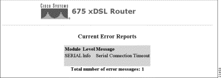
Click Ports. The Port Statistics screen appears. This screen allows you to display statistics on the Ethernet and WAN ports.

Step 1 Select a port from the drop down menu.
Step 2 Click Load Statistics. The statistics for the port are displayed as shown below.
Step 3 Repeat for all ports for which you want to display statistics.
Click Information to get information about the Cisco equipment you are working on and about Cisco Systems.
![]()
![]()
![]()
![]()
![]()
![]()
![]()
![]()
Posted: Sat Sep 28 01:08:23 PDT 2002
All contents are Copyright © 1992--2002 Cisco Systems, Inc. All rights reserved.
Important Notices and Privacy Statement.