|
|

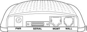
Figure A-2 through Figure A-4 show the connectors located on the rear panels of the Cisco 600 series CPEs.


The following ports are located on the backside of the Cisco 600 series CPEs.
| Interface | 626 | 627 | 633 | 673 | 675 | 675e | 676 | 677 | 678 |
|---|---|---|---|---|---|---|---|---|---|
Serial (Blue) - Serial Interface |
|
| ¸ |
|
|
|
|
|
|
¸ | ¸ |
|
|
|
|
|
|
| |
|
|
| ¸ | ¸ | ¸ | ¸ | ¸ | ¸ | |
¸ | ¸ | ¸ | ¸ | ¸ | ¸ | ¸ | ¸ | ¸ | |
¸ | ¸ | ¸ | ¸ | ¸ | ¸ | ¸ | ¸ | ¸ | |
PHONE (gray) - Phone interface (must use microfilter between PHONE port and telephone) |
|
|
|
|
|
|
|
| ¸ |
|
|
|
| ¸ |
|
|
|
|
These interfaces are described in the following sections.
The serial interface uses 12-in-1 V.35 Data Terminal Equipment (DTE) serial connector. This interfface connects to a 5-in-1 V.35 Data Communications Equipment (DCE) serial port on a Cisco router.

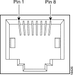
The LAN interface uses an Ethernet port that conforms to the IEEE 802.3 and 802.3u protocols and supports 10 or 100 Mbps half-duplex or full-duplex data rates on Category 3 (10 Mbps) or Category 5 (10/100 Mbps) twisted-pair wire up to 100 meters. The Ethernet connector is an RJ-45. Table A-3 shows the connector pinouts.
| Pin | Signal |
|---|---|
1 | TXD+ |
2 | TXD- |
3 | RXD+ |
6 | RXD- |

The LAN interface uses an RJ-45 connector that conforms to the ATM Forum Specification for ATM 25.6 Mbits over a category 5 twisted-pair wire up to 100 meters. Table A-4 shows the connector pinouts.
| Pin | Signal |
|---|---|
7 | TXD+ |
8 | TXD- |
1 | RXD+ |
2 | RXD- |

The management port uses an RJ-45 connector.
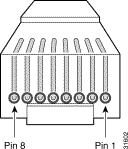
If you are not using a management cable ordered from Cisco, use the pinouts in Table A-5 for the DB-9 end of the serial cable used to connect the management port to the serial port of the PC.
Table A-5 shows the connector pinouts for the management port and the DB-9 end of the serial cable.
| Signal | Management Port (RJ-45 Pin) | RJ-45-to-DB-9 Serial Cable (DB-9 Pin) | Signal |
|---|---|---|---|
Do not connect | 1 | 1 | Do not connect |
Do not connect | 2 | 4 | Do not connect |
Do not connect | 3 | 6 | Do not connect |
Ground | 4 | 5 | Ground |
RX (input to the Cisco 600 series CPEs product) | 5 | 3 | RX (output from the PC/terminal) |
TX (output from the Cisco 600 series CPEs product) | 6 | 2 | TX (input to the PC/terminal) |
Do not connect | 7 | 7 | Do not connect |
Do not connect | 8 | 8 | Do not connect |
|
| 9 | Do not connect |
 |
Caution Do not connect pins 1, 2, 3, 7, and 8 of the RJ-45 end of the serial cable or pins 1, 4, 6, 7, 8, and 9 of the DB-9 end of the serial cable. Connecting these pins might damage the CPE. |


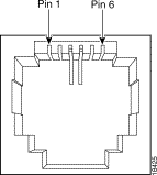
The ADSL/SDSL port uses an RJ-11 connector. Table A-6 shows the connector pinouts for the ADSL/SDSL connector.
| Pin | Signal |
|---|---|
3 | Ring |
4 | Tip |

The Phone port uses an RJ-11 connector. Table A-7 shows the connector pinouts for the Phone connector.
| Pin | Signal |
|---|---|
3 | Ring |
4 | Tip |

![]()
![]()
![]()
![]()
![]()
![]()
![]()
![]()
Posted: Fri May 4 14:18:38 PDT 2001
All contents are Copyright © 1992--2001 Cisco Systems, Inc. All rights reserved.
Important Notices and Privacy Statement.