|
|

Table Of Contents
Node Line Card Interface Configuration
Interim Interswitch Signaling Protocol Interfaces
Configuring the NLC Interface Clock
OC-3 NLC and OC-12 NLC Interface Options
Configuring the OC-3 and OC-12 Interface Options
Verifying the OC-3 and OC-12 Interface Configuration
Configuring the DS3 Interface Options
Verifying the DS3 Interface Configurations
Troubleshooting the NLC Interface Configuration
Node Line Card Interface Configuration
The plug-and-play mechanisms of the Cisco 6400 allow it to come up automatically. All configuration information for node line cards (NLCs) can be saved between hot swaps and switch reboots, while interface types are automatically discovered by the switch, eliminating mandatory manual configuration.
This chapter describes how to manually configure ATM interfaces for the Cisco 6400 NLC, as opposed to using Interim Local Management Interface (ILMI) autoconfiguration (which senses the peer interface type and appropriately configures the system interfaces).
The network configuration modifications described in this chapter are used to explicitly specify your ATM network operation. Although the Cisco 6400 defaults to a working configuration suitable for most networks, you might need to customize the configuration for your network.
This chapter contains the following sections:
•
NLC Interface Identification
•
•
NLC Interface Identification
In the Cisco 6400, NLC interface addresses specify the physical location of each port on the system. The address is composed of a three-part number in the format slot/subslot/port:
•
•
•
Interfaces maintain the same address, even while other cards are installed in or removed from the chassis. If, however, you move an NLC to a different slot or subslot, the address changes to reflect the new slot and subslot.
Autoconfiguration
Enabled by default, autoconfiguration determines the interface type each time an interface initially comes up. To manually configure an NLC interface, you must disable autoconfiguration.
Disabling Autoconfiguration
Autoconfiguration is enabled by default, but can be disabled to manually configure an NLC interface.
To disable autoconfiguration on an interface, use the following commands beginning in global configuration mode:
Step 1
Switch(config)# interface atm slot/subslot/port
Selects the NLC interface.
Step 2
Switch(config-if)# no atm auto-configuration
Disables autoconfiguration on the interface.
Example
In the following example, autoconfiguration is disabled on the interface ATM 1/0/0:
!interface atm 1/0/0no atm auto-configuration!Default NLC Interface Configuration
When autoconfiguration is disabled, the NLC interface assumes the default configuration shown in Table 4-1.
Verifying Autoconfiguration
To check if autoconfiguration is enabled or disabled on an NLC interface, use the show atm interface EXEC command.
In the following example, autoconfiguration is disabled on the OC-3 ATM interface 1/0/0:
Switch# show atm interface atm 1/0/0Interface: ATM1/0/0 Port-type: oc3suniIF Status: UP Admin Status: upAuto-config: disabled AutoCfgState: not applicable
IF-Side: Network IF-type: NNIUni-type: not applicable Uni-version: not applicableMax-VPI-bits: 8 Max-VCI-bits: 14Max-VP: 255 Max-VC: 16383Svc Upc Intent: pass Signalling: EnabledATM Address for Soft VC: 47.0091.8100.0000.0040.0b0a.2b81.4000.0c80.8000.00Configured virtual links:PVCLs SoftVCLs SVCLs PVPLs SoftVPLs SVPLs Total-Cfgd Installed-Conns3 0 0 0 0 0 3 3Logical ports(VP-tunnels): 0Input cells: 234663 Output cells: 2354835 minute input rate: 0 bits/sec, 0 cells/sec5 minute output rate: 0 bits/sec, 0 cells/secInput AAL5 pkts: 153211, Output AAL5 pkts: 153626, AAL5 crc errors: 0Switch#ATM Interface Types
This section describes how to configure NLC interfaces of the following types:
•
•
Note
User-Network Interfaces
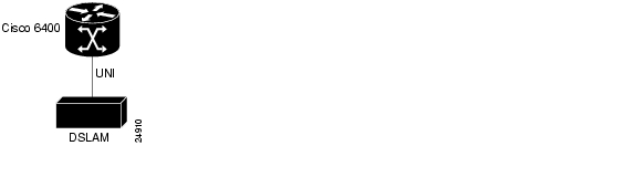
The User-Network Interface (UNI) specification defines communications between ATM-based products (a router or an ATM switch) located in a private network and the ATM switches located within the public carrier networks.
Figure 4-1 shows example UNIs configured between the Cisco 6400 and a digital subscriber line access multiplexer (DSLAM).
Figure 4-1 UNI Example
Note
Configuring UNIs
To manually configure an interface as UNI, complete the following steps, beginning in global configuration mode:
Step 1
Switch(config)# interface atm slot/subslot/port
Specifies the ATM interface and enters interface configuration mode.
Step 2
Switch(config-if)# no atm auto-configuration
Disables autoconfiguration on the interface.
Step 3
Switch(config-if)# atm uni [side {private | public}
type {network | user} version {3.0 | 3.1 | 4.0}]Configures the ATM UNI.
Step 4
Switch(config-if)# atm maxvpi-bits bits
(Optional) 0-8. Modifies the maximum VPI1 bits configuration.
Step 5
Switch(config-if)# atm maxvci-bits bits
(Optional) 0-14. Modifies the maximum VCI2 bits configuration.
1 VPI = virtual path identifier
2 VCI = virtual channel identifier
Example
In the following example, ATM 3/0/0 is configured as the private side of a UNI connection:
!interface atm 3/0/0no atm auto-configurationatm uni side user type private version 4.0!Verifying UNI Configuration
To verify UNI configuration for an ATM interface, use the show atm interface EXEC command:
Switch# show atm interface atm 3/0/0Interface: ATM0/1/0 Port-type: oc3suniIF Status: UP Admin Status: upAuto-config: disabled AutoCfgState: not applicable...Network-to-Network Interfaces
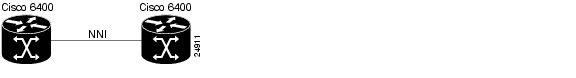
The Network-to-Network Interface (NNI) standard defines communication between two ATM switches that are both located in a private network or are both located in a public network. The interface between a public switch and private one is defined by the UNI standard.
Figure 4-2 shows example NNIs configured between two central office (CO) Cisco 6400 systems.
Figure 4-2 Private NNI Interface Example
Note
Configuring NNIs
To manually configure an interface as an NNI, complete the following steps, beginning in global configuration mode:
Example
In the following example, ATM 3/0/0 is configured as an NNI:
!interface atm 3/0/0no atm auto-configurationatm nni!Verifying NNI Configuration
To verify NNI configuration for an ATM interface, use the show atm interface EXEC command:
Switch# show atm interface atm 3/0/0Interface: ATM3/0/0 Port-type: oc3suniIF Status: UP Admin Status: upAuto-config: disabled AutoCfgState: not applicableUni-type: not applicable Uni-version: not applicable...Interim Interswitch Signaling Protocol Interfaces
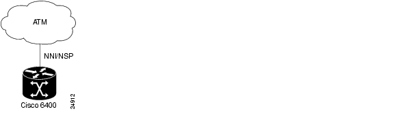
The Interim Interswitch Signalling Protocol (IISP) defines a static routing protocol (using manually configured prefix tables) for communication between ATM switches. IISP provides support for switched virtual circuits (SVCs) on ATM switches that do not support the Private Network-to-Network Interface (PNNI) protocol. For more information, see the "Configuring ATM Routing and PNNI" chapter in the ATM Switch Router Software Configuration Guide.
Figure 4-3 shows an example IISP interface that connects the Cisco 6400 to a switch in the ATM cloud.
Figure 4-3 IISP Interface Example
Configuring IISP Interfaces
To manually configure an IISP interface, complete the following steps beginning in global configuration mode:
Example
In the following example, ATM 3/0/0 is configured as the user side of an IISP connection:
!interface atm 3/0/0no atm auto-configurationatm iisp side user!atm route 47.0091.8100.0000.0000.0ca7.ce01 atm 3/0/0!Verifying IISP Interface Configuration
To verify IISP interface configuration, use the show atm interface EXEC command:
Switch# show atm interface atm 3/0/0Interface: ATM3/0/0 Port-type: oc3suniIF Status: UP Admin Status: upAuto-config: disabled AutoCfgState: not applicableUni-type: not applicable Uni-version: V3.0Max-VPI-bits: 8 Max-VCI-bits: 14Max-VP: 255 Max-VC: 16383ConfMaxSvpcVpi: 255 CurrMaxSvpcVpi: 255ConfMaxSvccVpi: 255 CurrMaxSvccVpi: 255ConfMinSvccVci: 35 CurrMinSvccVci: 35Svc Upc Intent: pass Signalling: EnabledATM Address for Soft VC: 47.0091.8100.0000.00e0.4fac.b401.4000.0c80.8000.00Configured virtual links:PVCLs SoftVCLs SVCLs TVCLs PVPLs SoftVPLs SVPLs Total-Cfgd Inst-Conns3 0 0 0 0 0 0 3 2Logical ports(VP-tunnels): 0Input cells: 264089 Output cells: 2732535 minute input rate: 0 bits/sec, 0 cells/sec5 minute output rate: 0 bits/sec, 0 cells/secInput AAL5 pkts: 172421, Output AAL5 pkts: 176993, AAL5 crc errors: 0NLC Interface Clocking
Each NLC port can be configured to support the following clocking options:
•
•
•
For detailed information on network clocking, see the "Network Clocking" section on page 2-14.
Configuring the NLC Interface Clock
To select the transmit clock source for a port, complete the following steps, beginning in global configuration mode:
Example
In the following example, ATM 4/0/0 is configured with a network-derived transmit clock source:
!network-clock-select 1 atm 2/0/0network-clock-select 2 atm 2/0/1network-clock-select 3 atm 1/0/0!interface atm 4/0/0!OC-3 NLC and OC-12 NLC Interface Options
The OC-3 NLC and OC-12 NLC support the following Synchronous Optical Network (SONET) and Synchronous Digital Hierarchy (SDH) framing modes:
•
•
•
•
The OC-3 NLC and OC-12 NLC support the following scrambling modes, both turned on by default:
•
•
Configuring the OC-3 and OC-12 Interface Options
To configure framing and scrambling on the OC-3 NLC and OC-12 NLC, complete the following steps beginning in global configuration mode:
Example
In the following example, both cell-payload scrambling and STS-stream scrambling are disabled for the OC-3 interface ATM 1/0/0. Also, the SONET mode of operation is set to SDH/STM-1.
!interface atm 1/0/0no scrambling cell-payloadno scrambling sts-streamsonet sts-3c!Verifying the OC-3 and OC-12 Interface Configuration
To verify successful configuration of OC-3 or OC-12 interfaces, use the show controller atm EXEC command. Check that the output displays the correct interface options.
Switch# show controller atm 7/0/0Redundancy NOT Enabled on interfaceIF Name: ATM7/0/0 Chip Base Address(es): A8B08000, 0 Port type: OC3 Port rate: 155 Mbps Port medium: SM FiberPort status:Good Signal Loopback:None Flags:8308TX Led: Traffic Pattern RX Led: Traffic Pattern TX clock source: network-derivedFraming mode: sts-3cCell payload scrambling onSts-stream scrambling on...DS3 NLC Interface Options
The DS3 NLC supports the following framing modes:
•
•
•
•
The DS3 NLC supports the cell payload scrambling mode, which scrambles only the payload of the cell (not the header). Cell payload scrambling is turned off by default.
The DS3 NLC defaults to a short line buildout, which supports cables less than 50 feet long. If the cable attached to the DS3 interface is longer than 50 feet, you must configure the long line buildout.
The DS3 NLC automatic far-end receive failure (FERF) alarms support the following values, all turned on by default:
•
•
•
•
•
Configuring the DS3 Interface Options
To manually change any of the default configuration values, complete the following steps, beginning in global configuration mode:
Example
In the following example, the DS3 interface ATM 3/0/0 is configured for C-bit with the ATM direct mapping framing mode and a short line buildout.
!interface atm 3/0/0framing cbitadmlbo short!Verifying the DS3 Interface Configurations
To verify successful configuration of DS3 interfaces, use the show controllers atm EXEC command. Check that the output displays the interface options you configured.
Switch# show controllers atm 1/1/0IF Name:ATM1/1/0, Chip Base Address:A8C08000Port type:DS3 Port rate:45000 Kbps Port medium:CoaxPort status:Good Signal Loopback:None Flags:8108TX Led:Traffic Pattern RX Led:Traffic Pattern TX clock source:network-derivedDS3 Framing Mode: cbit plcpFERF on AIS is onFERF on LCD is on (n/a in PLCP mode)FERF on RED is onFERF on OOF is onFERF on LOS is onLBO:<= 225'Cell payload scrambling on...Troubleshooting the NLC Interface Configuration
Table 4-2 describes commands that you can use to confirm proper configuration of the hardware, software, and interfaces for the Cisco 6400. Unless otherwise specified, all of the commands can be used in EXEC mode.
For more information on these commands, see the ATM and Layer 3 Switch Router Command Reference.
![]()
![]()
![]()
![]()
![]()
![]()
![]()
![]()
Posted: Wed Nov 10 16:26:07 PST 2004
All contents are Copyright © 1992--2004 Cisco Systems, Inc. All rights reserved.
Important Notices and Privacy Statement.