|
|

This chapter describes the major components of the Cisco 6400 Carrier-Class Broadband Aggregator.
This chapter includes the following sections:
 |
Note The illustrations in this guide depict the original Cisco 6400 chassis. Your chassis may appear or look slightly different. |
The Cisco 6400 is a broadband concentrator that features Cisco end-to-end ATM services, Point-to-Point Protocol (PPP) termination, and tunneling. The Cisco 6400 combines Cisco IOS ATM switching and routing capabilities in a modular, scalable, redundant, Network Equipment Building Systems/European Telecommunication Standards Institute (NEBS/ETSI)-compliant chassis.
This section includes detailed information about the following Cisco 6400 components and features:
The Cisco 6400 chassis, designed for mounting in 19-inch or 23-inch equipment racks, consists of the following:
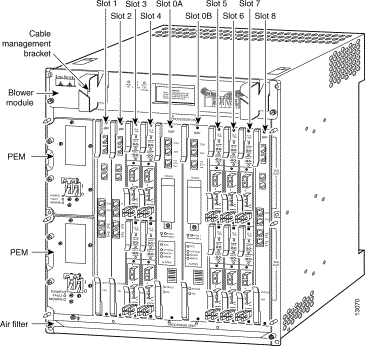
The module compartment has ten slots: two central slots that are reserved for NSP cards, and eight slots that can accommodate a mixture of full-height NRP cards, and full-height and half-height NLCs. All cards support hot-swapping and redundancy. Figure 1-1 shows a fully-loaded chassis with redundant cards and power entry modules (PEMs).
 |
Note The NSP card supports hot-swapping. One NSP is required for the system to operate, so hot-swapping a nonredundant NSP will result in a system outage. A standby NSP in a redundant configuration can be hot-swapped without impacting system operation. |

The blower module (Figure 1-2) is located on the top of the chassis and is connected to the backplane. The module provides airflow throughout the system. The air intake is located at the bottom of the chassis, and there is an exhaust in the top rear of the chassis through the blower module. The blower module supports hot-swapping and can be replaced without interruption to system operation.
 |
Note The system will shut down after two minutes if the blower module is removed and not replaced. |

Table 1-1 describes the blower module LEDs on the front center panel.
| LED | Status | Condition |
|---|---|---|
Steady green | Fans are operational. | |
Single Fan Failure | Steady yellow | One fan has failed and alarms are triggered. |
Multiple Fan Failure | Steady yellow | Two or more fans have failed and the system will shut down. |
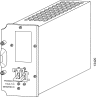
The DC PEM (Figure 1-3) provides filtering, and supplies DC power to the chassis electronics. There are two PEM bays in the chassis; however, only one PEM is required. An additional PEM can be used for redundancy. The PEMs are located on the left side of the chassis and are installed from the front. Input source power (-48 VDC from building centralized power source) enters the chassis through screw terminals on the rear of the chassis and is supplied to the PEMs when they are plugged into the backplane.
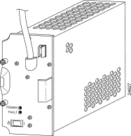
The AC PEM (Figure 1-4) provides power conversion directly from the facility VAC input power to the -48 VDC used internally in the Cisco 6400 chassis. AC power comes into the AC PEM through a power cord attached to the front faceplate.
 |
Note The Cisco 6400 no longer features the AC-Input Power Shelf. If your Cisco 6400 chassis has an AC-Input Power Shelf and this component requires replacement, Cisco will send you the new AC PEM (Cisco part number PEM-PWR-AC=) to replace the older unit. If you want to use AC power as the sole input and your Cisco 6400 chassis contains DC PEMs, you must remove the DC PEMs and replace them with the AC PEMs. Instructions for removing and installing DC PEMs and AC PEMs are provided in "Maintaining the Cisco 6400." |

Table 1-2 describes the LEDs located on the front panel of the PEM.
| LED | Status | Condition |
|---|---|---|
Power | Steady green | Power is available. |
Fault | Steady yellow | The PEM has failed or is turned off. |
Miswire | Steady yellow | Cables are attached incorrectly and should be reversed. |

Table 1-3 describes the LEDs located on the front panel of the PEM.
| LED | Status | Condition |
|---|---|---|
Power | Steady green | Power is available. |
Fault | Steady yellow | The PEM has failed or is turned off. |
The backplane is attached to the rear of the Cisco 6400 chassis and provides system interconnect.
The Node Switch Processor (NSP) (Figure 1-5) is the main system processor card in the Cisco 6400, residing in chassis slot 0A or 0B. The NSP contains the ATM switch engine and processor, and most memory components. The NSP runs the system software, which maintains and executes the management functions that control the system.

The NSP is a three-card module, which supports the following functions and features:
The LEDs on the NSP indicate the module status conditions (Table 1-4).
| LED | Status | Condition |
|---|---|---|
STATUS
| Steady yellow | Cisco IOS software is not running. |
FAIL | Yellow | NSP has failed. |
| ETH | ||
ACT (Activity) | Green | Packets are being transmitted and received. |
LNK (Link) | Steady green | Port is operational. |
PCMCIA Slot 0 | Steady green | Slot is active. |
PCMCIA Slot 1 | Steady green | Slot is active. |
| ALARMS | ||
Yellow | Alarm is active. | |
MAJOR | Yellow | Alarm is active. |
MINOR | Yellow | Alarm is active. |
The NSP with Stratum 3 BITS timing (NSP-S3B) supports the same functions and features as the standard NSP, as well as the following:
Figure 1-6 shows the faceplate of the NSP with Stratum 3 BITS timing.

By default, the NSP-S3B functions exactly the same as the standard NSP. You must specifically configure the NSP-S3B to implement the Stratum 3 BITS timing features. All content in this document that refers to the NSP also applies to the NSP-S3B.
The two PCMCIA card slots can be used to store Cisco IOS software or system configuration information on a PCMCIA disk memory card. The system can also boot from the software stored on the PCMCIA disk memory card.
The alarm cut-off (ACO) switch is located near the center of the NSP faceplate. Press the switch to turn off audible alarms. You can also disable audible alarms by using the command-line interface (CLI). For more information, refer to Cisco 6400 Command Reference.
The NSP card has three ports with RJ-45 connectors:
The console port is a serial EIA/TIA-232 interface. Table 1-5 lists the signals for the console port connector.
 |
Note The console port on the NSP does not support hardware flow control. To ensure proper operation, please configure any terminal equipment connected to the console port for no hardware flow control or no flow control. |
| Pin | Signal | Direction | Description |
|---|---|---|---|
1 | RTS | - | Hard wired to pin 8 |
2 | DTR | Output | Data terminal ready (for modem control) |
3 | TxD | Output | Transmit data |
4 | GND | - | Signal ground |
5 | GND | - | Signal ground |
6 | RxD | Input | Receive data |
7 | DSR | Input | Data set ready (for modem control) |
8 | CTS | - | Hard wired to pin 1 |
The auxiliary port supports hardware flow control and modem control. Table 1-6 lists the signals for the auxiliary port connector.
| Pin | Signal | Direction | Description |
|---|---|---|---|
1 | RTS | Output | Request to send (hardware flow control) |
2 | DTR | Output | Data terminal ready (modem control) |
3 | TxD | Output | Transmit data |
4 | GND | - | Signal ground |
5 | GND | - | Signal ground |
6 | RxD | Input | Receive data |
7 | DSR | Input | Data set ready (modem control) |
8 | CTS | Input | Clear to send (hardware flow control) |
The network management Ethernet (NME) port provides out-of-band network management of the NSP. Table 1-7 lists the signals for the NME port connector.
| Pin | Signal | Direction | Description |
|---|---|---|---|
1 | TxD+ | Output | Transmit data + |
2 | TxD- | Output | Transmit data - |
3 | RxD+ | Input | Receive data + |
4 | NC | - | No connection |
5 | NC | - | No connection |
6 | RxD- | Input | Receive data - |
7 | NC | - | No connection |
8 | NC | - | No connection |
The node route processor (NRP) receives traffic from one or more NSP ATM switch ports, reassembles the ATM cells into packets, routes the packets, segments the routed packets, and sends them back to the ATM switch. The Cisco 6400 can contain multiple NRP modules, configured to operate independently or as redundant pairs (1+1). You can insert NRPs into slots 1 through 8 in the Cisco 6400 chassis.
The Cisco 6400 supports two node route processors, designated as NRP-2SV and NRP-1:
These two types of NRPs can be used together in any combination in a single Cisco 6400 chassis.
This section describes the hardware components for an NRP-2SV module.

 |
Warning Class 1 laser product. To see translations of this warning, refer to the Regulatory Compliance and Safety Information document that accompanied this device. |
The LEDs on the NRP-2SV indicate port and module status (Table 1-8).
| LED | Status | Condition |
|---|---|---|
STATUS | Steady green | NRP-2SV is active. |
FAIL | Steady yellow | NRP-2SV has failed. |
| GBIC | ||
TX | Blinking green | Packets are being transmitted. |
RX | Blinking green | Packets are being received. |
LNK | Steady green | Port is operational. |
Table 1-9 lists the GBICs and their respective cable types and lengths.
| GBIC | Wavelength (nm) | Fiber Type | Core Size (microns) | Modal Bandwidth (MHz/km) | Cable Distance |
|---|---|---|---|---|---|
1000BASE-SX | 850 | MMF | 62.5 | 160 | 722 ft (220 m) |
1000BASE-LX/LH | 1300 | MMF1 | 62.5 | 500 | 1804 ft (550 m) |
The NRP-2SV faceplate also has a four-digit alphanumeric display that indicates status information and error codes.
This section describes the hardware components on the NRP-1 module.

The LEDs on the NRP-1 indicate port and module status (Table 1-10).
| LED | Status | Condition |
|---|---|---|
STATUS | Steady green | NRP is active (primary). |
FAIL | Steady yellow | NRP has failed. |
| ETH | ||
| ACT (Activity) | Blinking green | Packets are being transmitted and received. |
LNK (Link) | Steady green | Port is operational. |
| FE | ||
| ACT (Activity) | Blinking green | Packets are being transmitted and received. |
LNK (Link) | Steady green | Port is operational. |
The NRP-1 card has four ports with RJ-45 connectors:
The console port is a serial EIA/TIA-232 interface. Table 1-11 lists the signals for the console port connector.
| Pin | Signal | Direction | Description |
|---|---|---|---|
1 | NC | - | No connection |
2 | DTR | Output | Data terminal ready (for modem control) |
3 | TxD | Output | Transmit data |
4 | GND | - | Signal ground |
5 | GND | - | Signal ground |
6 | RxD | Input | Receive data |
7 | DSR | Input | Data set ready |
8 | NC | - | No connection |
 |
Note The console port on the NRP does not support hardware flow control. To ensure proper operation, configure any terminal equipment connected to the console port for no hardware flow control or no flow control. |
The auxiliary port supports hardware flow control and modem control. Table 1-12 lists the signals for the auxiliary port connector.
| Pin | Signal | Direction | Description |
|---|---|---|---|
1 | RTS | Output | Request to send (for hardware flow control) |
2 | DTR | Output | Data terminal ready (for modem control) |
3 | TxD | Output | Transmit data |
4 | GND | - | Signal ground |
5 | GND | - | Signal ground |
6 | RxD | Input | Receive data |
7 | DSR | Input | Data set ready (for modem control) |
8 | CTS | Input | Clear to send (for hardware flow control) |
Table 1-13 lists the signals for the Ethernet port connector.
| Pin | Signal | Direction | Description |
|---|---|---|---|
1 | TxD+ | Output | Transmit data + |
2 | TxD- | Output | Transmit data - |
3 | RxD+ | Input | Receive data + |
4 | NC | - | No connection |
5 | NC | - | No connection |
6 | RxD- | Input | Receive data - |
7 | NC | - | No connection |
8 | NC | - | No connection |
Table 1-14 lists the signals for the Fast Ethernet port connector.
| Pin | Signal | Direction | Description |
|---|---|---|---|
1 | TxD+ | Output | Transmit data + |
2 | TxD- | Output | Transmit data - |
3 | RxD+ | Input | Receive data + |
4 | NC | - | No connection |
5 | NC | - | No connection |
6 | RxD- | Input | Receive data - |
7 | NC | - | No connection |
8 | NC | - | No connection |
The Cisco 6400 supports three half-height and one full-height node line card (NLC) modules:
The Cisco 6400 can contain multiple NLC modules, configured to operate independently or as redundant pairs. NLCs can be inserted into slots 1 through 8 (subslots 0 and 1) in the Cisco 6400 chassis.
The three types of NLC can be configured to support the following clocking options:


 |
Warning Class 1 laser product. To see translations of this warning, refer to the Regulatory Compliance and Safety Information document that accompanied this device. |
 |
Warning Because invisible radiation may be emitted from the aperture of the port when no fiber cable is connected, avoid exposure to radiation and do not stare into open apertures. To see translations of this warning, refer to the Regulatory Compliance and Safety Information document that accompanied this device. |
 |
Warning Invisible laser radiation present. To see translations of this warning, refer to the Regulatory Compliance and Safety Information document that accompanied this device. |
| |
Varning! | Osynlig laserstrålning när denna del är öppen och förregleringen är urkopplad. Rikta inte blicken in mot strålen. |
| |
Varoitus | Alleviates ja suojalukitus ohitettaessa olet alttiina näkymättömälle lasersäteilylle. Äjä katso säteeseen. |


 |
Warning Class 1 laser product. To see translations of this warning, refer to the Regulatory Compliance and Safety Information document that accompanied this device. |
 |
Warning Because invisible radiation may be emitted from the aperture of the port when no fiber cable is connected, avoid exposure to radiation and do not stare into open apertures. To see translations of this warning, refer to the Regulatory Compliance and Safety Information document that accompanied this device. |
 |
Warning Invisible laser radiation present. To see translations of this warning, refer to the Regulatory Compliance and Safety Information document that accompanied this device. |
| |
Varning! | Osynlig laserstrålning när denna del är öppen och förregleringen är urkopplad. Rikta inte blicken in mot strålen. |
| |
Varoitus | Alleviates ja suojalukitus ohitettaessa olet alttiina näkymättömälle lasersäteilylle. Äjä katso säteeseen. |
The LEDs on the three types of NLC provide status and operational information about port connections (Table 1-15 and Table 1-16).
| LED | Status | Condition |
|---|---|---|
FAIL | Steady yellow | NLC has failed |
| PORT 0 (top connector) | ||
TX (transmit) | Green | Transmit activity |
RX (receive) | Green | Receive activity |
STATUS | Green | Active (primary) |
| PORT 1 (bottom connector) | ||
TX (transmit) | Green | Transmit activity |
RX (receive) | Green | Receive activity |
STATUS | Steady green | Active |
| LED | Status | Condition |
|---|---|---|
FAIL | Steady yellow | OC-12/STM-4 NLC has failed |
TX (transmit)
| Green | Transmit activity |
RX (receive) | Green | Receive activity |
STATUS | Green | Active (primary) |
![]()
![]()
![]()
![]()
![]()
![]()
![]()
![]()
Posted: Fri Jul 5 10:53:37 PDT 2002
All contents are Copyright © 1992--2002 Cisco Systems, Inc. All rights reserved.
Important Notices and Privacy Statement.