|
|

This chapter describes the Layer 2 tunnel protocol (L2TP) features supported in Cisco IOS Release 12.1(5)DB/DC.
Defined by RFC 2661, L2TP is an emerging Internet Engineering Task Force (IETF) standard that combines the best features of two existing tunneling protocols: Cisco's Layer 2 Forwarding (L2F) and Microsoft's Point-to-Point Tunneling Protocol (PPTP). For a description, benefits, restrictions, and configuration information for L2TP, see the Cisco IOS Release 12.0(1) T Layer 2 Tunnel Protocol feature module and the Configuring Virtual Private Networks chapter of the Cisco IOS Dial Services Configuration Guide: Network Services, Release 12.1.
L2TP Tunnel Service Authorization
Static tunnel service authorization does not support switched virtual channels (SVCs).
When using a RADIUS service profile for tunnel service authorization, the NRP configured as an L2TP tunnel switch must forward all sessions through L2TP tunnels. The L2TP tunnel switch must not terminate any of the sessions.
The total number of precloned interfaces must not exceed 3000 on the Cisco 6400 NRP.
Cisco Express Forwarding
To support over 1000 sessions, you must enable Cisco Express Forwarding (CEF) with the ip cef global configuration command. For more information on CEF, see the "Cisco Express Forwarding" chapter of the Cisco IOS Switching Services Configuration Guide .
Cisco recommends at least 128 MB of DRAM on the Cisco 6400 NRP while using these feature enhancements.
Configuring L2TP involves the following tasks:
| Command | Purpose | |
|---|---|---|
Step 1 | vpdn enable
| Enables VPDN and informs the router to look for tunnel definitions from an LNS. |
Step 2 | vpdn group group-number
| Defines a local group number identifier for which other VPDN variables can be assigned. Valid group numbers range between 1 and 3000. |
Step 3 | request dialin [l2f |
l2tp] ip ip-address {domain | Enables the router to request a dial-in tunnel to an IP address if the dial-in user belongs to a specific domain or the dial-in user dialed a specific DNIS. |
| Command | Purpose | |
|---|---|---|
Step 1 | vpdn enable
| Enables VPDN and informs the router to look for tunnel definitions from an LNS. |
Step 2 | vpdn group group-number
| Defines a local group number identifier for which other VPDN variables can be assigned. Valid group numbers range between 1 and 3000. |
Step 3 | accept dialin [l2f | l2tp |
any] virtual-template | Allows the LNS to accept an open tunnel request from the specified remote peer, define the Layer 2 protocol to use for the tunnel, and identify the virtual template to use for cloning virtual access interfaces. |
At this point, you can configure the virtual template interface with configuration parameters you want to apply to virtual access interfaces. A virtual template interface is a logical entity configured for a serial interface. The virtual template interface is not tied to any physical interface and is applied dynamically as needed. Virtual access interfaces are cloned from a virtual template interface, used on demand, and then freed when no longer needed. Enter the following commands to create and configure a virtual template interface beginning in global configuration mode:
| Command | Purpose | |
|---|---|---|
Step 1 | interface virtual-template
number
| Creates a virtual template interface and enters interface configuration mode. |
Step 2 | ip unnumbered ethernet 0
| Enables IP without assigning a specific IP address on the LAN. |
Step 3 | encapsulation ppp
| Enables PPP encapsulation on the virtual template interface, which will be applied to virtual access interfaces. |
Step 4 | ppp authentication pap |
chap
| Enables PAP or CHAP authentication on the virtual template interface, which will be applied to virtual access interfaces. |
Optionally, you can configure other commands for the virtual template interface. For information about configuring virtual template interfaces, see the "Configuring Virtual Template Interfaces" chapter in the Dial Solutions Configuration Guide.
Refer to the "Important Notes" section of the Cisco 6400 NRP - Release Notes for Cisco IOS Release 12.1(5)DC to learn about scaling and enhancing VPDN and L2TP features.
 |
Note Static tunnel service authorization does not support SVCs. |
2. Tunnel Service Authorization—The user profile on the RADIUS server provides a list of domains accessible to the user, enabling tunnel service authorization for the client-supplied domain. If successful, the LAC establishes an L2TP tunnel.
You can configure the static domain name on the PVC or on the VC class.
To configure the static domain name on the PVC, enter the following commands beginning in global configuration mode:
| Command | Purpose | |
|---|---|---|
Step 1 | Router(config)#interface atm 0/0/0[.subinterface-number] | Specifies the ATM interface and optional subinterface. |
Step 2 | Router(config-subif)#no ip directed-broadcast
| Disables forwarding of directed broadcasts. |
Step 3 | Router(config-subif)# | Configures a PVC on the ATM interface or subinterface. |
Step 4 | Router(config-if-atm-vc)# | Sets encapsulation as PPP. Also specifies the virtual template interface to clone for the new virtual access interface. |
Step 5 | Router(config-if-atm-vc))# | Configures the static domain name on the PVC. |
To configure the static domain name on the VC class, enter the following commands beginning in global configuration mode:
| Command | Purpose | |
|---|---|---|
Step 1 | Router(config)#vc-class atm vc-class-name
| Creates and names a map class. |
Step 2 | Router(config-vc-class)#encapsulation aal5mux ppp
Virtual-Template number
| Sets encapsulation as PPP. Also specifies the virtual template interface to clone for the new virtual access interface. |
Step 3 | Router(config-vc-class)#vpn service domain-name
| Configures the static domain name on the VC class. |
Step 4 | Router(config-vc-class)#exit
| Returns to global configuration mode. |
Step 5 | Router(config)#interface atm 0/0/0[.subinterface-number] | Specifies the ATM interface and optional subinterface. |
Step 6 | Router(config-subif)# | Applies VC class to all VCs on the ATM interface or subinterface. |
To verify that you successfully configured the static domain name, enter the show running-config EXEC command.
To enable the LAC to perform domain authorization before tunneling, enter the following command in global configuration mode:
| Command | Purpose |
|---|---|
Router(config)#vpdn authorize domain
| Enables domain preauthorization. |
To check that you successfully enabled domain preauthorization, enter the show running-config EXEC command.
To enable the LAC to communicate properly with the RADIUS server for tunnel service authorization, enter the following commands in global configuration mode:
| Command | Purpose | |
|---|---|---|
Step 1 | Router(config)#radius-server
host {hostname | | Specifies the RADIUS server host. |
Step 2 | Router(config)#radius-server attribute nas-port | Selects the ATM VC extended NAS port format for RADIUS accounting features. |
Step 3 | Router(config)# | Specifies the authentication and encryption key for all RADIUS communications between the router and the RADIUS daemon. |
Step 4 | Router(config)# | Configures the LAC to recognize and use vendor-specific attributes. |
To check that you successfully configured the LAC to communicate properly with the RADIUS server for tunnel service authorization, enter the show running-config EXEC command.
To enable domain preauthorization, enter the following configuration in the user profile on the RADIUS server:
| RADIUS Entry | Purpose |
|---|---|
nas-port:ip-address:slot/subslot/port/vpi.vci
| Configures the NAS port username for domain preauthorization. |
Password = "cisco"
| Sets the fixed password. |
User-Service-Type = Outbound-User
| Configures the service-type as outbound. |
Cisco-AVpair = "vpdn:vpn-domain-list=domain1, domain2,..."
| Specifies the domains accessible to the user. |
Syntax Description
ip-address | Management IP address of the NSP. |
slot/subslot/port | Specify ATM interface. |
vpi.vci | VPI and VCI values for the PVC. |
domain | Domain to configure as accessible to the user. |
To verify the RADIUS user profile, refer to the user documentation for your RADIUS server.
| RADIUS Entry | Purpose |
|---|---|
domain Password "cisco"
| Sets the fixed password. |
User-Service-Type = Outbound-User
| Configures the service-type as outbound. |
Cisco-AVpair = "vpdn:tunnel-id=name"
| Specifies the name of the tunnel that must match the LNS's VPDN terminate-from hostname. |
Cisco-AVpair = "vpdn:l2tp-tunnel-password=secret"
| Specifies the secret (password) for L2TP tunnel authentication. |
Cisco-AVpair = "vpdn:tunnel-type=l2tp"
| Specifies Layer 2 Tunnel Protocol. |
Cisco-AVpair = "vpdn:ip-addresses=ip-address"
| Specifies IP address of LNS. |
Syntax Description
domain
| Client-supplied domain. |
name
| Name of the tunnel that must match the LNS's VPDN terminate-from hostname statement. |
secret
| Secret (password) used for L2TP tunnel authentication. |
ip-address
| IP address of LNS. |
To verify the RADIUS service profile, refer to the user documentation for your RADIUS server.
This section contains the following examples:
Static Domain Name Configuration on a PVC Example
The following example shows the static domain names "net1.com" and "net2.com" assigned to PVCs on an ATM interface. All PPP sessions originating from PVC 30/33 are sent to the "net1.com" L2TP tunnel, while all PPP sessions originating from PVC 30/34 are sent to the "net2.com" tunnel.
!
interface ATM 0/0/0.33 multipoint
  pvc 30/33
   encapsulation aal5ciscoppp Virtual-Template1
   vpn service net1.com
  !
  pvc 30/34
   encapsulation aal5ciscoppp Virtual-Template1
   vpn service net2.com
  !
Static Domain Name Configuration on a VC Class Example
In the following example, the static domain name "net.com" is assigned to a VC class. The VC class is then assigned to the VCs on an ATM subinterface.
!
vc-class ATM MyClass
  encapsulation aal5ciscoppp Virtual-Template1
  vpn service net.com
  !
interface ATM 0/0/0.99 multipoint
  class-int MyClass
  no ip directed-broadcast
  pvc 20/40
  pvc 30/33
  !
Domain Preauthorization Configuration on the LAC Example
The following example shows the configuration necessary for the LAC to participate in domain preauthorization:
!
aaa new-model
aaa authorization network default local group radius
!
vpdn authorize domain
!
radius-server host 10.9.9.9 auth-port 1645 acct-port 1646
radius-server attribute nas-port format d
radius-server key MyKey
radius-server vsa send authentication
!
Domain Preauthorization RADIUS User Profile Example
The following example shows a domain preauthorization RADIUS user profile:
user = nas-port:10.9.9.9:0/0/0/30.33{
 profile_id = 826
 profile_cycle = 1
 radius=Cisco {
 check_items= {
 2=cisco
 }
 reply_attributes= {
 9,1="vpdn:vpn-domain-list=net1.com,net2.com"
 6=5
 }
 }

 }
Tunnel Service Authorization Configuration on the LAC Example
The following example shows the configuration necessary for the LAC to participate in tunnel service authorization:
!
aaa new-model
aaa authorization network default local group radius
!
radius-server host 10.9.9.9 auth-port 1645 acct-port 1646
radius-server attribute nas-port format d
radius-server key MyKey
radius-server vsa send authentication
!
Tunnel Service Authorization RADIUS Service Profile Example
The following example shows a tunnel service authorization RADIUS service profile:
user = net1.com{
profile_id = 45
profile_cycle = 18
member = me
radius=Cisco {
check_items= {
2=cisco
}
reply_attributes= {
9,1="vpdn:tunnel-id=LAC-1"
9,1="vpdn:l2tp-tunnel_password=MySecret"
9,1="vpdn:tunnel-type=l2tp"
9,1="vpdn:ip-addresses=10.10.10.10"
6=5
}
}
}
This feature enables the initiate-to command to limit the number of sessions per L2TP tunnel.
To limit the number of sessions per tunnel without using a RADIUS server, complete the following steps on the NRP-LAC beginning in global configuration mode:
| Command | Purpose | |
|---|---|---|
Step 1 | Router(config)#vpdn-group number
| Selects the VPDN group. |
Step 2 | Router(config-vpdn)#request-dialin
| Enables the LAC to request L2TP tunnels to the LNS. Enters VPDN request-dialin group mode. |
Step 3 | Router(config-vpdn-req-in)#protocol l2tp
| Specifies the Layer 2 Tunnel Protocol. |
Step 4 | Router(config-vpdn-req-in)#or
Router(config-vpdn-req-in)#or
Router(config-vpdn-req-in)# | Initiates a tunnel based on the LAC's host name or ingress tunnel ID.
Initiates a tunnel based on the client-supplied domain name.
Initiates a tunnel based on the user's DNIS number. |
Step 5 | Router(config-vpdn-req-in)#exit
| Returns to VPDN group mode. |
Step 6 | Router(config-vpdn)# | Specifies the LNS IP address and the maximum number of sessions per tunnel. Optionally specifies the priority of the IP address (1 is highest). |
In the following example, the LAC initiates up to three tunnels. Each tunnel is limited to 40 sessions.
!
vpdn-group 1
 request-dialin
  protocol l2tp
  domain net.com
 initiate-to ip 10.1.1.1 limit 40
 initiate-to ip 10.2.2.2 limit 40
 initiate-to ip 10.2.2.2 limit 40
!
Step 2 Enter the show vpdn tunnel privileged EXEC command to verify that the number of displayed sessions does not exceed your configured limit.
Router# show vpdn tunnel


L2TP Tunnel Information (Total tunnels 50 sessions 2000)

LocID RemID Remote Name   State  Remote Address  Port Sessions

41234 7811  LNS1          est    10.1.1.1        1701 40
20022 2323  LNS1          est    10.1.1.1        1701 40
41234 7811  LNS2          est    10.1.2.2        1701 40
59765 3477  LNS2          est    10.1.3.3        1701 40
...
To use a RADIUS server to limit the number of sessions per tunnel, enter the following Cisco-AVpair attributes in the RADIUS service profile.
This attribute specifies the IP addresses of the LNSes to receive the L2TP connections.
Cisco-AVpair = "vpdn:ip-addresses=address1[<delimiter>address2][<delimiter>address3]..." Syntax Description
address | IP address of the LNS. | |
<delimiter> | , (comma) | Selects load sharing among IP addresses. |
(space) | Selects load sharing among IP addresses. | |
/ (slash) | Groups IP addresses on left side in higher priority than the right side. | |
In the following example, the LAC sends the first PPP session through a tunnel to 10.1.1.1, the second PPP session to 10.2.2.2, the third to 10.3.3.3. The fourth PPP session is sent through the tunnel to 10.1.1.1, and so forth. If the LAC fails to establish a tunnel with any of the IP addresses in the first group, then the LAC attempts to connect to those in the second group (10.4.4.4 and 10.5.5.5).
Example (RADIUS Freeware Format)
Cisco-AVpair="vpdn:ip-addresses=10.1.1.1,10.2.2.2,10.3.3.3/10.4.4.4,10.5.5.5"
Example (CiscoSecure ACS for UNIX)
9,1="vpdn:ip-addresses=10.1.1.1,10.2.2.2,10.3.3.3/10.4.4.4,10.5.5.5"
This attribute specifies the maximum number of sessions in each tunnel to the IP addresses listed with the vpdn:ip-addresses attribute.
Cisco-AVpair = "vpdn:ip-address-limits=limit1 [limit2] [limit3]... " Syntax Description
limit | Maximum number of sessions per tunnel to the corresponding IP address. | |
Example (RADIUS Freeware Format)
Cisco-AVpair="vpdn:ip-address-limits=10 20 30 40 50 "
Example (CiscoSecure ACS for UNIX)
9,1="vpdn:ip-address-limits=10 20 30 40 50 "
|
Note You must enter a space between the final limit entry and the end quotation marks. |
The following example shows a tunnel service authorization RADIUS service profile, along with the session limiting entry. IP addresses 10.1.1.1 and 10.2.2.2 are assigned priority 1, while IP addresses 10.3.3.3 and 10.4.4.4 are assigned priority 2. Tunnels to 10.1.1.1 are limited to 100 sessions, tunnels to 10.2.2.2 are limited to 200 sessions, tunnels to 10.3.3.3 are limited to 300 sessions, and tunnels to 10.4.4.4 are limited to 400 sessions.
user = net.com{
profile_id = 45
profile_cycle = 18
member = me
radius=Cisco {
check_items= {
2=cisco
}
reply_attributes= {
9,1="vpdn:tunnel-id=LAC-1"
9,1="vpdn:l2tp-tunnel_password=MySecret"
9,1="vpdn:tunnel-type=l2tp"

9,1="vpdn:ip-addresses=10.1.1.1 10.2.2.2/10.3.3.3 10.4.4.4"

9,1="vpdn:ip-address-limits=100 200 300 400 "
6=5
}
}
}
To verify the RADIUS service profile, refer to the user documentation for your RADIUS server.
This feature enables sessions authorized with different domains to share the same tunnel.
To implement the tunnel sharing feature, complete the following steps on the NRP-LAC beginning in global configuration mode:
| Command | Purpose | |
|---|---|---|
Step 1 | Router(config)#vpdn-group number
| Selects the VPDN group. |
Step 2 | Router(config-vpdn)#request-dialin
| Enables the LAC to request L2TP tunnels to the LNS. Enters VPDN request-dialin group mode. |
Step 3 | Router(config-vpdn-req-in)#protocol l2tp
| Specifies the Layer 2 Tunnel Protocol. |
Router(config-vpdn-req-in)#or
Router(config-vpdn-req-in)#or
Router(config-vpdn-req-in)# | Initiates a tunnel based on the LAC's host name or ingress tunnel ID.
Initiates a tunnel based on the client-supplied domain name.
Initiates a tunnel based on the user's DNIS number. Note Repeat Step 4 to enter all keys chosen for tunnel sharing. | |
Step 5 | Router(config-vpdn-req-in)#exit
| Returns to VPDN group mode. |
Step 6 | Router(config-vpdn)# | Specifies the LNS IP address. Optionally specifies the priority of the IP address (1 is highest). |
Step 7 | Router(config-vpdn)# | Enables tunnel sharing among the keys entered in Step 4. |
In the following example, all sessions that are locally authorized through VPDN group 1 are sent through the same tunnel to 10.1.1.1.
!
vpdn-group 1
 request-dialin
  protocol l2tp
  domain net1.com
  domain net2.com
 initiate-to ip 10.1.1.1
 tunnel share
!
Enter the show running-config EXEC command to check that you successfully enabled the tunnel sharing feature.
To implement the tunnel sharing feature, enter the following Cisco-AVpair attributes in the RADIUS service profile.
This attribute specifies the group to which the service belongs. All services with matching group names are considered members of the same VPDN group.
Cisco-AVpair = "vpdn:vpdn-group=group-name" Syntax Description
group-name | Group to which the service belongs. |
Example (RADIUS Freeware Format)
Cisco-AVpair="vpdn:vpdn-group=group1"
Example (CiscoSecure ACS for UNIX)
9,1="vpdn:vpdn-group=group1"
This attribute indicates that the tunnel sharing feature is enabled for the service.
Cisco-AVpair = "vpdn:tunnel-share=yes" Syntax Description
This attribute has no arguments or keywords.
Example (RADIUS Freeware Format)
Cisco-AVpair="vpdn:tunnel-share=yes"
Example (CiscoSecure ACS for UNIX)
9,1="vpdn:tunnel-share=yes"
In the following example, both the net1.com and net2.com services are members of the "group1" VPDN group. With tunnel sharing enabled in both service profiles, the sessions for net1.com and net2.com will be combined and sent through the same tunnels.
user = net1.com{
profile_id = 45
profile_cycle = 18
member = me
radius=Cisco {
check_items= {
2=cisco
}
reply_attributes= {
9,1="vpdn:tunnel-id=LAC-1"
9,1="vpdn:l2tp-tunnel_password=MySecret"
9,1="vpdn:tunnel-type=l2tp"
9,1="vpdn:ip-addresses=10.10.10.10"

9,1="vpdn:vpdn-group=group1"

9,1="vpdn:tunnel-share=yes"
6=5
}
}
}

user = net2.com{
profile_id = 45
profile_cycle = 18
member = me
radius=Cisco {
check_items= {
2=cisco
}
reply_attributes= {
9,1="vpdn:tunnel-id=LAC-1"
9,1="vpdn:l2tp-tunnel_password=MySecret"
9,1="vpdn:tunnel-type=l2tp"
9,1="vpdn:ip-addresses=10.10.10.10"

9,1="vpdn:vpdn-group=group1"

9,1="vpdn:tunnel-share=yes"
6=5
}
}
}
To verify the RADIUS service profile, refer to the user documentation for your RADIUS server.
|
Note When using a RADIUS service profile for tunnel service authorization, the NRP configured as an L2TP tunnel switch must forward all sessions through L2TP tunnels. The L2TP tunnel switch must not terminate any of the sessions. |
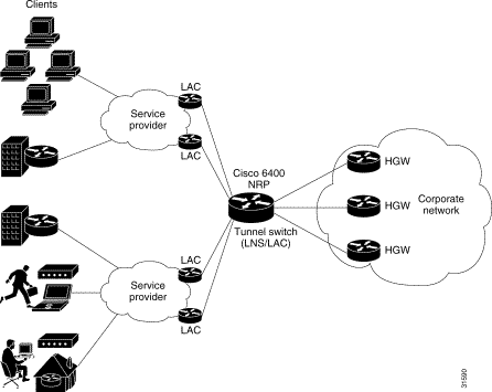
The L2TP Tunnel Switching feature enables the Cisco 6400 node route processor (NRP) to terminate tunnels from LACs and forward the sessions through new L2TP tunnels selected independently of the client-supplied domains. The NRP as a tunnel switch performs VPDN tunnel authorization based on the ingress tunnel names that are mapped to specified LNSes.
Figure 2-1 shows an example network topology using the L2TP tunnel switching feature.
See the following procedures to configure the L2TP Tunnel Switching feature. The listed tasks are required to configure the L2TP tunnel switch.
|
Note The NRP as a tunnel switch requires at least two VPDN groups: one to handle incoming tunnels from the LAC, and one to create the L2TP tunnels/sessions to the LNS. |
To use the L2TP Tunnel Switching feature, you must first enable VPDN and multihop capabilities by entering the following commands beginning in global configuration mode:
| Command | Purpose | |
|---|---|---|
Step 1 | Router(config)#vpdn enable
| Enables VPDN functionality. |
Step 2 | Router(config)#vpdn multihop
| Enables VPDN multihop functionality. |
To verify that you enabled VPDN and multihop functionality, enter the show running-config EXEC command.
To terminate the tunnel from the LAC, enter the following commands beginning in global configuration mode:
| Command | Purpose | |
|---|---|---|
Step 1 | Router(config)#username remote-hostname password secret
| Configures the secret (password). Must match the secret configured on the LAC. |
Step 2 | Router(config)#username local-name password secret
| Configures the secret (password). Must match secret in Step 1. |
Step 3 | Router(config)#vpdn-group number
| Selects the VPDN group. |
Step 4 | Router(config-vpdn)#accept-dialin
| Accepts incoming L2TP tunnel connections. Enters VPDN accept-dialin group mode. |
Step 5 | Router(config-vpdn-acc-in)#protocol l2tp
| Specifies the Layer 2 Tunnel Protocol. |
Step 6 | Router(config-vpdn-acc-in)#virtual-template number
| Specifies the virtual template interface to use to clone the new virtual access interface. |
Step 7 | Router(config-vpdn-acc-in)#exit
| Returns to VPDN group mode. |
Step 8 | Router(config-vpdn)# | Specifies the host name of the remote LAC that will be required when accepting a VPDN tunnel. Must match remote-hostname in Step 1. |
Step 9 | Router(config-vpdn)# | Specifies the local host name of the tunnel. Must match local-name in Step2. |
To verify that you successfully configured the tunnel switch to terminate tunnels from the LAC, enter the show running-config EXEC command.
To map the ingress tunnel name to an LNS, complete the following steps beginning in global configuration mode:
| Command | Purpose | |
|---|---|---|
Step 1 | Router(config)#username username password secret
| Configures the secret (password). Username must match LNS's hostname or tunnel ID. Secret must match the secret configured on the LNS. |
Step 2 | Router(config)#username egress-tunnel-name
password secret
| Configures the secret (password). Must match secret in Step 1. |
Step 3 | Router(config)#vpdn-group number
| Selects the VPDN group. |
Step 4 | Router(config-vpdn)#request-dialin
| Enables the tunnel switch to request L2TP tunnels to the LNS. Enters VPDN request-dialin group mode. |
Step 5 | Router(config-vpdn-req-in)#protocol l2tp
| Specifies the Layer 2 Tunnel Protocol. |
Step 6 | Router(config-vpdn-req-in)# | Initiates a tunnel based on the LAC's hostname or ingress tunnel ID. |
Step 7 | Router(config-vpdn-req-in)#exit
| Returns to VPDN group mode. |
Step 8 | Router(config-vpdn)# | Specifies the LNS. Optionally specifies the maximum number of sessions per tunnel as well as the priority of the IP address (1 is highest). |
Step 9 | Router(config-vpdn)# | Specifies the local host name of the tunnel. Must match egress-tunnel-name in Step 2. |
To verify that you successfully mapped the ingress tunnel name to the LNS, enter the show running-config EXEC command.
To specify how to perform VPDN tunnel authorization searches, enter the following command in global configuration mode:
| Command | Purpose |
|---|---|
Router(config)#vpdn search-order multihop-hostname [domain]
| Specifies a search by the configured ingress tunnel name. Optionally specifies to search by domain or DNIS if the first search type fails. |
To verify that you successfully configured the tunnel switch to perform VPDN tunnel authorization searches by ingress tunnel name, enter the show running-config EXEC command.
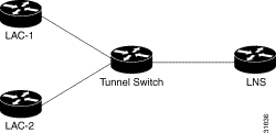
The examples in this section show the configurations necessary for the basic L2TP tunnel switch topology shown in Figure 2-2. In this topology, a tunnel switch terminates tunnels from two LACs and forwards all the sessions through one tunnel to the LNS.
This section provides the following configuration examples:
In the following example, LAC-1 performs tunnel authorization based on domain name and initiates a tunnel to the L2TP tunnel switch:
!
vpdn enable
!
username net.com password Secret1
username Tunnel-Switch-In password Secret1
!
vpdn-group 1
 request-dialin
  protocol l2tp
  domain service1.net.com
 initiate-to ip 10.1.1.1
 local name net.com
!
In the following example, LAC-2 also performs tunnel authorization based on domain name and initiates a tunnel to the L2TP tunnel switch:
!
vpdn enable
!
username net.com password Secret2
username Tunnel-Switch-In password Secret2
!
vpdn-group 1
 request-dialin
  protocol l2tp
  domain service2.net.com
 initiate-to ip 10.1.1.1
 local name net.com
!
L2TP Tunnel Switch Configuration Example
In the following example, the NRP is configured as an L2TP tunnel switch. VPDN groups 1 and 2 are used to terminate the tunnels from the LAC. VPDN group 11 is used to initiate the tunnel to the LNS, and it performs tunnel authorization based on the configured ingress tunnel name.
!
vpdn enable
vpdn multihop
vpdn search-order multihop-hostname domain
!
username net.com password Secret1
username Tunnel-Switch-In password Secret1
username net.com password Secret2
username Tunnel-Switch-In password Secret2
username LNS password Secret3
username Tunnel-Switch-Out password Secret3
!
vpdn-group 1
 accept-dialin
  protocol l2tp
  virtual-template 1
 terminate-from hostname net.com
 local name Tunnel-Switch-In
!
vpdn-group 11
 request-dialin
  protocol l2tp
  multihop hostname net.com
 initiate-to ip 10.2.2.2
 local name Tunnel-Switch-Out
!
interface ATM 0/0/0.1001 point-to-point
 ip address 10.1.1.1 255.255.255.0
 pvc 5/10
 encapsulation aal5snap
!
interface Virtual-Template 1
 ip unnumbered FastEthernet 0/0/0
 no ip directed-broadcast
 no keepalive
 no peer default ip address
 ppp authentication chap
!
In the following example, the LNS terminates the tunnel from the L2TP tunnel switch:
vpdn enable
!
username LNS password Secret3
username Tunnel-Switch-Out password Secret3
!
vpdn-group 1
 accept-dialin
  protocol l2tp
  virtual-template 1
 terminate-from hostname Tunnel-Switch
 local name LNS
!
interface Virtual-Template 1
 ip unnumbered FastEthernet 0/0/0
 no ip directed-broadcast
 ip mroute-cache
 no keepalive
 peer default ip address pool pool-1
 ppp authentication chap
!
|
Note The total number of precloned interfaces must not exceed 3000 on the Cisco 6400 NRP. |
Before configuring this feature, see the L2TP Scalability Prerequisites.
By improving L2TP control connection processing and virtual template cloning, these enhancements provide resilience to dropouts between the L2TP access concentrator (LAC) and L2TP network server (LNS). See the "Important Notes" section of the Cisco 6400 NRP - Release Notes for Cisco IOS Release 12.1(5)DC for a list of supported scalability numbers and the recommended commands for achieving those numbers.
To accommodate more incoming control messages in the queue, set the maximum number of packets to a high value (at least 1000 packets on the Cisco 6400). Use the following steps on the interfaces between the LAC and LNS, beginning in global configuration mode.
| Command | Purpose | |
|---|---|---|
Step 1 | Router(config)# interface atm slot/subslot/port
| Selects the ATM interface. |
Step 2 | Router(config-if)# hold-queue length in
| Specifies the maximum number of packets in the input queue. |
To display the current hold queue setting and the number of packets discarded because of hold queue overflows, enter the EXEC command show interfaces.
Precloning virtual access interfaces at the LNS reduces the load on the system during call setup. Enter the following commands to preclone a virtual access interface, beginning in global configuration mode.
| Command | Purpose | |
|---|---|---|
Step 1 | Router(config)# virtual-template template-number | Specifies the number of virtual access interfaces to be created and cloned from a specific virtual template. |
|
Note The precloning operation might take a long time to complete (on the order of minutes for a large number of interfaces). Avoid incoming calls at the LNS until precloning is finished. You can monitor the precloning operation with the show vtemplate privileged EXEC command. |
To check the successful precloning of virtual access interfaces, enter the privileged EXEC command show vtemplate.
By default, the system uses 10 L2TP tunnel control channel retransmission attempts. To change the number of retries, enter the following commands beginning in global configuration mode.
| Command | Purpose | |
|---|---|---|
Step 1 | Router(config)# vpdn-group number
| Selects the VPDN group. |
Step 2 | Router(config-vpdn)# | Specifies the number of retransmission attempts. |
To check the configured number of retransmission attempts, enter the EXEC command show running-config. To check general control channel retransmission parameters, enter the privileged EXEC command show vpdn tunnel all.
Control channel retransmissions follow an exponential backoff, starting at the minimum retransmission timeout, and ending at the maximum retransmission timeout. Enter the following commands to change the timeout lengths beginning in global configuration mode.
| Command | Purpose | |
|---|---|---|
Step 1 | Router(config)# vpdn-group number
| Selects the VPDN group. |
Step 2 | Router(config-vpdn)# | Specifies the minimum timeout for retransmissions. |
Step 3 | Router(config-vpdn)# | Specifies the maximum timeout (up to 8 seconds) for retransmissions. |
To determine the best minimum and maximum timeouts for a given topology, enter the privileged EXEC command show vpdn tunnel all. Check the displayed retransmit time distribution.
Retransmit time distribution: 0 0 0 0 1 0 0 0 1
Each value corresponds to the number of retransmissions at 0, 1, 2,..., 8 seconds, respectively, displaying a histogram of all tunnel retransmission times.
To check the configured control channel retransmission timeouts, enter the EXEC command show running-config. To check general control channel retransmission parameters, enter the privileged EXEC command show vpdn tunnel all.
The default local receive window size (RWS) is now 3000 packets for a Cisco 6400 NRP. This allows the L2TP control channel to send requests as fast as possible. To change the local RWS, enter the following commands beginning in global configuration mode.
| Command | Purpose | |
|---|---|---|
Step 1 | Router(config)#vpdn-group number
| Selects the VPDN group. |
Step 2 | Router(config-vpdn)# | Specifies the size of advertised receive window. |
Step 3 | Router(config-vpdn)#exit
| Returns to global configuration mode. |
Step 4 | Router(config)#end
| Returns to privileged EXEC mode. |
Step 5 | Router#clear vpdn tunnel l2tp remote-name local-name
| Clears all sessions and drop the tunnel. |
To display the local RWS, enter the privileged EXEC command show vpdn tunnel all.
The tunnel timeout dictates how long a tunnel lingers after all its sessions are gone. This feature is useful if you expect sessions to come back immediately, or if you plan to examine the tunnel status after the sessions have ended. The default tunnel timeout is 10 seconds for an LNS and 15 seconds for a LAC. To set the L2TP tunnel timeout, enter the following commands beginning in global configuration mode.
| Command | Purpose | |
|---|---|---|
Step 1 | Router(config)#vpdn-group number
| Selects the VPDN group. |
Step 2 | Router(config-vpdn)#l2tp tunnel nosession-timeout seconds
| Specifies the tunnel timeout length. |
To check the configured tunnel timeout, enter the EXEC command show running-config.
For general L2TP configuration examples, see the Layer 2 Tunnel Protocol feature module.
The following example shows a configuration implementing the L2TP scalability enhancements. The input hold queue limit on an ATM interface is set to 1200, and virtual template 1 is used to preclone 2000 virtual access interfaces. VPDN group 1 is set to use 7 retransmission attempts, with the retransmission timeouts beginning at 2 seconds and ending at 4 seconds, and the L2TP tunnel timeout is set to 10 seconds. The local RWS is set to 500 packets.
!
vpdn enable
!
vpdn-group 1
 accept-dialin
  protocol l2tp
  virtual-template 1
 terminate from hostname LAC1
 local name LNS1
 l2tp tunnel receive-window 500
 l2tp tunnel nosession-timeout 10
 l2tp tunnel retransmit retries 7
 l2tp tunnel retransmit timeout min 2
 l2tp tunnel retransmit timeout max 4
!
virtual-template 1 pre-clone 2000
!
interface ATM 0/0/0
 hold-queue 1200 in
!
interface FastEthernet 0/0/0
 ip address negotiated
 no ip directed-broadcast
!
interface Virtual-Template 1
 ip unnumbered FastEthernet 0/0/0
 no ip directed-broadcast
 no logging event link-status
 no keepalive
 peer default ip address pool pool-1
 ppp authentication chap
!
To troubleshoot VPDN and L2TP, enter the privileged EXEC command debug vpdn. For sample output of debug vpdn, see the "Debug Examples" section in the Layer 2 Tunnel Protocol feature module.
You can also enter the privileged EXEC command show vpdn tunnel all, which contains new information for these L2TP scalability enhancements. The new fields are described in Table 2-1.
Router# show vpdn tunnel all


 L2TP Tunnel Information (Total tunnels=1 sessions=500)

 Tunnel id 20 is up, remote id is 12, 500 active sessions
   Tunnel state is established, time since change 00:00:33
   Remote tunnel name is LAC
     Internet Address 10.1.1.1, port 1701
   Local tunnel name is LNS
     Internet Address 10.1.1.2, port 1701
   971 packets sent, 1259 received, 19892 bytes sent, 37787 received
   Control Ns 501, Nr 746
   Local RWS 3000 (default), Remote RWS 3000 (max)
   Retransmission time 4, max 8 seconds
   Unsent queuesize 0, max 0
   Resend queuesize 251, max 261
   Total resends 390, ZLB ACKs 251
   Current nosession queue check 0 of 5
   Retransmit time distribution: 0 0 0 0 1 0 0 0 1
   Sessions disconnected due to lack of resources 0
| New field as appears in Example | Description |
|---|---|
Retransmission time 4, max 8 seconds | Current retransmit timeout for the tunnel; maximum retransmit timeout reached by the tunnel. |
Unsent queuesize 0, max 0 | Number of control packets waiting to be sent to the peer; maximum number of control packets in the unsent queue. |
Resend queuesize 251, max 261 | Number of control packets sent but not acknowledged; maximum number of unacknowledged control packets in the resend queue. |
Total resends 390, ZLB ACKs 251 | Total number of packets resent; number of zero length body acknowledgment messages sent. |
Current nosession queue check 0 of 5 | Number of tunnel timeout periods since the last session ended. Up to 5 tunnel timeouts are used if there are outstanding control packets on the unsent or resend queue. Otherwise, the tunnel is dropped after 1 tunnel timeout. |
Retransmit time distribution: 0 0 0 0 1 0 0 0 1 | Histogram showing the number of retransmissions at 0, 1, 2,..., 8 seconds, respectively. |
Sessions disconnected due to lack of resources 0 | Number of sessions for which there were no precloned interfaces available. By default, a request for a new session at an LNS is refused if a precloned interface is not available. |
Table 2-2 describes privileged EXEC commands that help you monitor and maintain VPDNs that use L2TP tunnels.
| Command | Purpose |
|---|---|
show vpdn tunnel [all | packets | state | summary | transport] | Displays VPDN tunnel information including tunnel protocol, ID, packets sent and received, receive window sizes, retransmission times, and transport status. |
show vpdn session [all [interface | tunnel | username]| | Displays VPDN session information including interface, tunnel, username, packets, status, and window statistics. |
clear vpdn tunnel l2tp remote-name local-name
| Shuts down a specific tunnel and all the sessions within the tunnel. |
Troubleshooting components in VPDN is not always straightforward because there are multiple technologies and OSI layers involved. Table 2-3 describes EXEC commands that will help you isolate and identify problems on VPDNs that use L2TP tunnels:
| Command | Purpose |
|---|---|
clear vpdn tunnel [l2f [nas-name | hgw-name] | l2tp [remote-name | Shuts down a specific tunnel and all the sessions within the tunnel. |
debug ppp negotiation
| Displays information about packets transmitted during PPP start-up and detailed PPP negotiation options. |
debug ppp chap
| Displays CHAP packet exchanges. |
debug vpdn event [protocol | flow-control]
| Displays VPDN errors and basic events within the protocol (such as L2TP, L2F, PPTP) and errors associated with flow control. Flow control is only possible if you are using L2TP and the remote peer "receive window" is configured for a value greater than zero. |
debug vpdn packet [control | data] [detail]
| Displays protocol-specific packet header information, such as sequence numbers if present, such as flags and length. |
show interface virtual access number
| Displays information about the virtual access interface, LCP, protocol states, and interface statistics. The status of the virtual access interface should be: " |
show vpdn session [all [interface | tunnel | username] | packets | Displays VPDN session information including interface, tunnel, username, packets, status, and window statistics. |
show vpdn tunnel [all [id | local-name | remote-name] | packets | Displays VPDN tunnel information including tunnel protocol, id, local and remote tunnel names, packets sent and received, tunnel, and transport status. |
![]()
![]()
![]()
![]()
![]()
![]()
![]()
![]()
Posted: Tue Feb 26 15:33:15 PST 2002
All contents are Copyright © 1992--2002 Cisco Systems, Inc. All rights reserved.
Important Notices and Privacy Statement.