|
|

Product Number: 6015-48XDSL-I/F=
This document provides an overview of and installation and replacement procedures for the Cisco 6015 digital subscriber line (DSL) interface module. The DSL interface module is a field-replaceable unit (FRU).
 |
Warning Only trained and qualified personnel should be allowed to install, replace, or service this equipment. |
This document includes the following sections:
The DSL interface module enables you to
Figure 1 shows the location of the DSL interface module in the Cisco 6015 chassis.
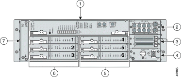
| 1 | NI-2 card | 5 | xDSL line cards (slots 4 to 6) |
| 2 | I/O1 module | 6 | xDSL line cards (slots 1 to 3) |
| 3 | DSL interface module | 7 | Fan module |
| 4 | DC PEM2 |
|
| 1I/O = input/output 2PEM = power entry module |
Figure 2 shows a close-up of the DSL interface module faceplate.
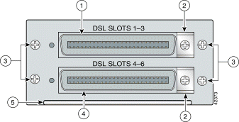
| 1 | 50-pin Champ connector for DSL slots 1 through 3 | 4 | 50-pin Champ connector for DSL slots 4 through 6 |
| 2 | Cable tie-downs | 5 | Extraction handle |
| 3 | Screws to secure the DSL interface module to the chassis |
|
Table 1 lists the specifications for the DSL interface module.
| Specification | Description |
Dimensions | Height: 1.375 in. (3.493 cm) Depth: 9.375 in. (23.813 cm) Width: 3.375 in. (8.573 cm) |
Weight | 0.71 lb (0.32 kg) |
Data connectors | Two 50-pin Champ connectors |
Power consumption | Not applicable. |
Minimum software and network management requirement | Cisco IOS—Release 12.1(4)DA CDM1—Release 3.2 (optional) |
| 1CDM = Cisco DSL Manager |
Table 2 lists the tools and equipment that you need to install and remove a DSL interface module.
| Check | Tools and Equipment |
|---|---|
| Hardware Components and Cables |
| DSL interface module. |
| Equipment necessary for ESD protection—You need this equipment whenever you handle Cisco chassis, modules, and cards. |
| One of the following cables for POTS splitter connections.
Note The wye-cable is used only with quad-port xTU-C line cards. |
|
Note If unshielded cable is used for FCC Class A or EN55022 Class A compliance, ferrites are needed. |
|
|
| Equipment necessary for ESD protection—You need this equipment whenever you handle Cisco chassis, modules, and cards. |
| Tools |
| Phillips-head or flat-head screwdriver. |
| Two Champ connector screws. |
| Tie wraps. |
| Software Components | |
Cisco IOS or CDM Note See Table 1 for minimum software and network management release requirements. |
This section describes the following areas:
 |
Note To see translations of the warnings that appear in this publication, refer to the Regulatory Compliance and Safety Information for the Cisco 6015 System document that accompanied this product. |
 |
Caution Before you start the installation procedures, read the entire document for important information and safety warnings. |
 |
Caution Proper ESD protection is required whenever you handle Cisco equipment. Installation and maintenance personnel should be properly grounded by means of grounding straps to eliminate the risk of ESD damage to the equipment. Equipment is subject to ESD damage whenever it is removed from the chassis. |
 |
Caution If fuses are already installed in the fuse and alarm panel, remove them. You can replace the fuses after the system is installed. Do not power up the system while you install and connect the system. |
 |
Caution If the power connections are improperly connected and power is applied while the cards are installed, the cards and chassis could be damaged. |
 |
Caution It is important that the chassis cooling fans run continuously while the system is powered. |
 |
Caution Any card that is only partially connected to the backplane can disrupt system operation. |
 |
Warning This warning symbol means danger. You are in a situation that could cause bodily injury. Before you work on any equipment, be aware of the hazards involved with electrical circuitry and be familiar with standard practices for preventing accidents. |
 |
Warning This unit is intended for installation in restricted access areas. A restricted access area is where access can only be gained by service personnel through the use of a special tool, lock and key, or other means of security, and is controlled by the authority responsible for the location. |
 |
Warning Only trained and qualified personnel should be allowed to install, replace, or service this equipment. |
 |
Warning To prevent personal injury or damage to the chassis, never attempt to lift or tilt the chassis using the handles on the port adapters; these types of handles are not designed to support the weight of the unit. Lift the unit only by grasping the chassis underneath its lower edge. |
 |
Warning Never attempt to lift the chassis with the handles on the power supplies or the switching modules. These handles are not designed to support the weight of the chassis. Using them to lift or support the chassis can result in severe damage to the equipment and serious bodily injury. |
 |
Warning Before opening the chassis, disconnect the telephone-network cables to avoid contact with telephone-network voltages. |
 |
Warning To prevent bodily injury when mounting or servicing this unit in a rack, you must take special precautions to ensure that the system remains stable. The following guidelines are provided to ensure your safety: —This unit should be mounted at the bottom of the rack if it is the only unit in the rack. —When mounting this unit in a partially filled rack, load the rack from the bottom to the top with the heaviest component at the bottom of the rack. —If the rack is provided with stabilizing devices, install the stabilizers before mounting or servicing the unit in the rack. |
 |
Warning Removing I/O cards, CPU cards, fans, and power supplies can expose you to high-energy (high-amperage) circuits and possible ejection of molten metal or to the shock hazard of telephony circuit voltages. Be sure to remove all rings, watches, and other jewelry from fingers, wrists, and arms before removing panels and devices. |
 |
Warning Use extreme care when removing or installing connectors so that you do not damage them. |
 |
Warning Use copper conductors only. |
 |
Warning A readily accessible two-poled disconnect device must be incorporated in the fixed wiring. |
 |
Warning You are in a situation that could cause bodily injury. Before you work on any equipment, be aware of the hazards involved with electrical circuitry and be familiar with standard practices for preventing accidents. |
 |
Warning Never install telephone wiring during an electrical storm. |
 |
Warning Do not reach into a vacant slot or chassis while you install or remove a card, a module, or a fan. Exposed circuitry could constitute an energy hazard. |
 |
Warning Blank faceplates and cover panels serve three important functions: they prevent exposure to hazardous voltages and currents inside the chassis; they contain electromagnetic interference (EMI) that might disrupt other equipment; and they direct the flow of cooling air through the chassis. Do not operate the system unless all cards, faceplates, front covers, and rear covers are in place. |
 |
Warning Never defeat the ground conductor or operate the equipment in the absence of a suitably installed ground conductor. Contact the appropriate electrical inspection authority or an electrician if you are uncertain that suitable grounding is available. |
 |
Warning When installing the unit, the ground connection must always be made first and disconnected last. |
 |
Warning For personal safety, the ground wire must connect to safety (earth) ground at both the equipment and supply side of the DC wiring (unless the local electrical code requirements are different). |
 |
Warning This equipment needs to be grounded. Use a green and yellow 12 to 14 AWG ground wire to connect the host to earth ground during normal use. |
 |
Warning Incorrect connection of this or connected equipment to a general purpose outlet could result in a hazardous situation. |
 |
Warning Read the installation instructions before you connect the system to its power source. |
 |
Warning Do not work on the system or connect or disconnect cables during periods of lightning activity. |
 |
Warning Use caution when installing or modifying telephone lines. |
 |
Warning To reduce the risk of fire, use only No. 26 AWG or larger telecommunication line cord. |
 |
Warning Secure all power cabling when installing this unit to avoid disturbing field-wiring connections. |
 |
Warning Before working on a system that has an on/off switch, turn OFF the power and unplug the power cord. |
 |
Warning This equipment will be inoperable when main power fails. |
 |
Warning The power supply circuitry for the equipment can constitute an energy hazard. Before you install or replace the equipment, remove all jewelry (including rings, necklaces, and watches). Metal objects can come into contact with exposed power supply wiring or circuitry inside the equipment. This could cause the metal objects to heat up and cause serious burns or weld the metal object to the equipment. |
 |
Warning Before working on a chassis or working near power supplies, unplug the power cord on AC units; disconnect the power at the circuit breaker on DC units. |
 |
Warning Do not touch the power supply when the power cord is connected. For systems with a power switch, line voltages are present within the power supply even when the power switch is off and the power cord is connected. For systems without a power switch, line voltages are present within the power supply when the power cord is connected. |
 |
Warning Ultimate disposal of this product should be handled according to all national laws and regulations. |
 |
Warning This chassis must be installed in a rack that is secured to the building structure. |
 |
Warning Make sure that your equipment rack is properly ventilated. |
 |
Warning The ports labeled "CNSL," "AUX," "ENET," "Tx," and "Rx (DS3)" are safety extra-low voltage (SELV) circuits. SELV circuits should only be connected to other SELV circuits. Because the Basic Rate Interface (BRI) circuits are treated like telephone-network voltage (TNV), avoid connecting the SELV circuit to the TNV circuits. |
 |
Warning This equipment is to be installed and maintained by service personnel only as defined by AS/NZS 3260 Clause 1.2.14.3 Service Personnel. |
 |
Warning Network hazardous voltages are present in the T1 PRI cable. If you detach the cable, detach the end away from the router first to avoid possible electric shock. Network hazardous voltages are also present in the area of the T1 PRI (RJ-48C) ports, regardless of whether power is off or on. |
 |
Warning The telecommunications lines must be disconnected 1) before unplugging the main power connector or 2) while the housing is open. |
 |
Warning Never install telephone jacks in wet locations unless the jack is specifically designed for wet locations. |
 |
Warning Do not use a telephone to report a gas leak in the vicinity of the leak. |
 |
Warning Avoid using a telephone (other than a cordless type) during an electrical storm. There may be a remote risk of electric shock from lightning. |
 |
Warning Hazardous network voltages are present in WAN ports regardless of whether power to the router is OFF or ON. To avoid electric shock, use caution when working near WAN ports. When detaching cables, detach the end away from the router first. |
 |
Warning To reduce the risk of electric shock when servicing any individual unit, disconnect the power cord or cords that connect the unit to the AC power strip or DC busbar. When working with a DC system, remove the busbar connector before working on a device. Exposed live voltages are present at the device end; exposure to these may cause injury. |
 |
Warning Do not use this product near water; for example, near a bath tub, wash bowl, kitchen sink or laundry tub, in a wet basement, or near a swimming pool. |
 |
Warning Never touch uninsulated telephone wires or terminals unless the telephone line has been disconnected at the network interface. |
 |
Warning During line card installation, wear grounding wrist straps to avoid ESD damage to the card. Do not directly touch the backplane with your hand or any metal tool, or you could shock yourself. |
 |
Warning This equipment is intended to be grounded. Ensure that the host is connected to earth ground during normal use. |
 |
Warning Metal objects heat up when connected to power and ground, and can cause serious burns. |
This section covers the following topics:
 |
Caution Any module that is only partially connected to the backplane can disrupt system operation. |
The DSL interface module is a FRU; however, it is not hot swappable. Removing the DSL interface module will interrupt the service for the entire system until it is replaced.
 |
Caution The DSL interface module must be installed and removed by a trained technician only. |
 |
Tip Use the ESD grounding jack on the fan module for all maintenance except when you are removing the fan module. Use the ESD grounding jack on the DC PEM when you are removing the fan module. |
Follow these guidelines to prevent ESD damage:
 |
Caution Periodically check the resistance value of the antistatic strap. Ensure that the measurement is between 1 and 10 megohms. |
The following sections describe how to remove or install a DSL interface module.
 |
Caution Proper ESD protection is required whenever you handle Cisco equipment. Installation and maintenance personnel should be properly grounded by means of grounding straps to eliminate the risk of ESD damage to the equipment. Equipment is subject to ESD damage whenever it is removed from the chassis. |
 |
Note If you are using AC power and the power cord is plugged in to the wall outlet, unplug it. If you are using DC power and the fuses are already installed in the fuse and alarm panel, remove them. You can replace the fuses after the system is installed and connected. The fuse and alarm panel is not provided by Cisco. |
 |
Tip Cisco recommends that you label each data cable at both ends to identify its destination. |
Complete the following steps to remove the DSL interface module from the Cisco 6015 chassis:
Step 2 Set the circuit breaker on the DC PEM to the OFF (0) position.
Step 3 Disconnect the two Champ connector cables from the front of the DSL interface module.
Step 4 Use a flat-head or Phillips-head screwdriver to unscrew the four screws that hold the DSL interface module to the Cisco 6015 chassis.
Step 5 Hold the extraction handle on the front of the module and firmly pull the module out of the slot.
See the "Installing the DSL Interface Module" section for DSL interface module installation procedures.
 |
Note If you are using AC power and the power cord is plugged in to the wall outlet, unplug it. If you are using DC power and the fuses are already installed in the fuse and alarm panel, remove them. You can replace the fuses after the system is installed and connected. The fuse and alarm panel is not provided by Cisco. |
 |
Caution Before installing or replacing the module, verify that the rack is securely stabilized. |
 |
TimeSaver Cisco recommends that you label each data cable at both ends to identify its destination. |
Complete the following steps to install the DSL interface module in the Cisco 6015 chassis:
Step 2 Verify that the circuit breaker on the DC PEM is set to the OFF (0) position.
Step 3 Horizontally align the module edges with the module guides at the right and left of the slot in the Cisco 6015.
Figure 3 shows the DSL interface module installation.
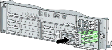
Step 4 Hold the extraction handle on the front of the module and gently apply pressure while carefully pushing the module into the slot.
Step 5 Push on the faceplate of the module to fully seat the module.
Step 6 Use a flat-head or Phillips-head screwdriver to attach the four screws to the Cisco 6015 chassis.
Step 7 Connect the DSL interface module to the POTS splitter (Cisco 6015 with a POTS splitter configuration) or MDF (Cisco 6015 without a POTS splitter configuration).
Use the cables that are described in the "Part and Tool Requirements" section to connect the DSL interface module to the POTS splitter or MDF. For cabling procedures for each POTS splitter, refer to the appropriate vendor documentation.
 |
Note If unshielded cable is used for FCC Class A or EN55022 Class A compliance, the cables will need to be looped through ferrites. |
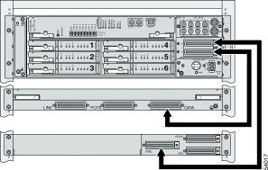
Figure 4 shows the cabling between the DSL interface module and a third-party POTS splitter. These connections are for xDSL data flow between the Cisco 6015 and the POTS splitter.
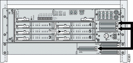
A system configuration using octal-port xTU-C line cards requires the installation of an additional POTS splitter. The additional POTS splitter expands the system capacity to 48 subscriber ports. Figure 5 shows the cabling between the DSL interface module and two third-party POTS splitters. These connections are for xDSL data flow between the Cisco 6015 and the POTS splitters.
Step 8 Use a flat-head screwdriver to screw in the Champ connectors and tie wrap the connector to the chassis, as shown in Figure 6.
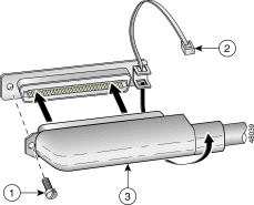
| 1 | Champ connector screw | 3 | Champ connector |
| 2 | Tie wrap |
|
Step 9 Plug the AC power cord into the wall outlet or reinsert the fuses in the fuse and alarm panel.
Step 10 Set the circuit breaker on the DC PEM to the ON (1) position.
The DSL interface module has the same standards as the Cisco 6015 system, as shown in Table 3.
| Area of Compliance | Compliance Standard |
|---|---|
Product Safety | UL 1950, 3rd Edition, EN 60950, AS/NZS 3260, IEC 950, |
Emissions | CISPR22, EN55022, AS/ANS 3548, ICES-003, VCCI, BSMI (CNS 13438) |
Immunity | EN61000-4-2, 3, 4, 5 and 6 / IEC-61000-4-2, 3, 4, 5 and 6; |
NEBS | Bellcore GR-63-CORE, GR-1089-CORE, SR-3590 Level 3 |
Telecom | FCC Part 68, CS-03, ACA TS 016: 1997, CTR 12 97/520/EC |
ETSI | 300-386-1, 300-386-2, 300-019 |
A complete list of all DSL product related documentation is available on the World Wide Web at http://www.cisco.com/univercd/cc/td/doc/product/dsl_prod/index.htm
The following sections explain how to obtain documentation from Cisco Systems.
You can access the most current Cisco documentation on the World Wide Web at the following URL:
Translated documentation is available at the following URL:
http://www.cisco.com/public/countries_languages.shtml
Cisco documentation and additional literature are available in a Cisco Documentation CD-ROM package, which is shipped with your product. The Documentation CD-ROM is updated monthly and may be more current than printed documentation. The CD-ROM package is available as a single unit or through an annual subscription. Registered Cisco.com users can order the Documentation CD-ROM through the online Subscription Store:
http://www.cisco.com/go/subscription
If you are reading Cisco product documentation on Cisco.com, you can submit technical comments electronically. Click Leave Feedback at the bottom of the Cisco Documentation home page. After you complete the form, print it out and fax it to Cisco at 408 527-0730.
You can e-mail your comments to bug-doc@cisco.com.
To submit your comments by mail, use the response card behind the front cover of your document, or write to the following address:
Cisco Systems
Attn: Document Resource Connection
170 West Tasman Drive
San Jose, CA 95134-9883
We appreciate your comments.
Cisco provides Cisco.com as a starting point for all technical assistance. Customers and partners can obtain documentation, troubleshooting tips, and sample configurations from online tools by using the Cisco Technical Assistance Center (TAC) Web Site. Cisco.com registered users have complete access to the technical support resources on the Cisco TAC Web Site.
Cisco.com is the foundation of a suite of interactive, networked services that provides immediate, open access to Cisco information, networking solutions, services, programs, and resources at any time, from anywhere in the world.
Cisco.com is a highly integrated Internet application and a powerful, easy-to-use tool that provides a broad range of features and services to help you to
You can self-register on Cisco.com to obtain customized information and service. To access Cisco.com, go to the following URL:
The Cisco TAC is available to all customers who need technical assistance with a Cisco product, technology, or solution. Two types of support are available through the Cisco TAC: the Cisco TAC Web Site and the Cisco TAC Escalation Center.
Inquiries to Cisco TAC are categorized according to the urgency of the issue:
Which Cisco TAC resource you choose is based on the priority of the problem and the conditions of service contracts, when applicable.
The Cisco TAC Web Site allows you to resolve P3 and P4 issues yourself, saving both cost and time. The site provides around-the-clock access to online tools, knowledge bases, and software. To access the Cisco TAC Web Site, go to the following URL:
All customers, partners, and resellers who have a valid Cisco services contract have complete access to the technical support resources on the Cisco TAC Web Site. The Cisco TAC Web Site requires a Cisco.com login ID and password. If you have a valid service contract but do not have a login ID or password, go to the following URL to register:
http://www.cisco.com/register/
If you cannot resolve your technical issues by using the Cisco TAC Web Site, and you are a Cisco.com registered user, you can open a case online by using the TAC Case Open tool at the following URL:
http://www.cisco.com/tac/caseopen
If you have Internet access, it is recommended that you open P3 and P4 cases through the Cisco TAC Web Site.
The Cisco TAC Escalation Center addresses issues that are classified as priority level 1 or priority level 2; these classifications are assigned when severe network degradation significantly impacts business operations. When you contact the TAC Escalation Center with a P1 or P2 problem, a Cisco TAC engineer will automatically open a case.
To obtain a directory of toll-free Cisco TAC telephone numbers for your country, go to the following URL:
http://www.cisco.com/warp/public/687/Directory/DirTAC.shtml
Before calling, please check with your network operations center to determine the level of Cisco support services to which your company is entitled; for example, SMARTnet, SMARTnet Onsite, or Network Supported Accounts (NSA). In addition, please have available your service agreement number and your product serial number.
This document is to be used in conjunction with the documents listed in the "Related Documentation" section.

Copyright © 2002, Cisco Systems, Inc.
All rights reserved.
![]()
![]()
![]()
![]()
![]()
![]()
![]()
![]()
Posted: Wed Jul 24 17:53:15 PDT 2002
All contents are Copyright © 1992--2002 Cisco Systems, Inc. All rights reserved.
Important Notices and Privacy Statement.