|
|

Table Of Contents
Cisco CRS-1 Carrier Routing System 16-Slot Line Card Chassis Unpacking, Moving,
and Securing GuideCisco Product Security Overview
Obtaining Technical Assistance
Obtaining Additional Publications and Information
Preparing to Unpack the Chassis
Preventing Electrostatic Discharge
Unpacking the Chassis and Components
Attaching the Dolly to the Chassis
Removing the Chassis Shipping Pallet
Dolly and Chassis Moving Guidelines
Verifying the Securing Location
Modifying the Dolly Configuration to Move the Chassis
Cisco CRS-1 Carrier Routing System 16-Slot Line Card Chassis Unpacking, Moving,
and Securing Guide
Created: February 22, 2006, 78-17535-02CDC Date September 29, 2006
Contents
This document presents the following topics:
•
Preparing to Unpack the Chassis
•
•
Documentation Overview
This section presents the following topics:
•
•
•
•
Objective
This document provides instructions for unpacking the Cisco CRS-1 16-slot line card chassis (LCC) and its components, attaching the dolly, moving the chassis safely, and securing the chassis to the floor. This document does not provide background information and basic theory-of-operation for anyone wanting to understand the Cisco CRS-1 Carrier Routing System.
Audience
This document is intended for line card chassis unpackers and Cisco installation partners who are responsible for moving and securing the line card chassis. No additional knowledge of routing or the Cisco IOS XR software is assumed.
Related Documentation
For complete planning, installation, and configuration information, refer to the following documents:
Hardware Documents
•
•
•
•
•
Software Documents
For a complete listing of software documentation available, refer to About Cisco IOS XR Software Documentation, available online at
http://www.cisco.com/univercd/cc/td/doc/product/core/crs/xrabout.htm.
Changes to This Document
Table 1 lists the technical changes made to this document since it was first printed.
Table 1 Changes to This Document
78-17535-02
September 2006
The document was updated with technical corrections.
78-17535-01
April 2006
Initial release of the document
Obtaining Documentation
Cisco documentation and additional literature are available on Cisco.com. Cisco also provides several ways to obtain technical assistance and other technical resources. These sections explain how to obtain technical information from Cisco Systems.
Cisco.com
You can access the most current Cisco documentation at this URL:
http://www.cisco.com/techsupport
You can access the Cisco website at this URL:
You can access international Cisco websites at this URL:
http://www.cisco.com/public/countries_languages.shtml
Product Documentation DVD
The Product Documentation DVD is a comprehensive library of technical product documentation on a portable medium. The DVD enables you to access multiple versions of installation, configuration, and command guides for Cisco hardware and software products. With the DVD, you have access to the same HTML documentation that is found on the Cisco website without being connected to the Internet. Certain products also have PDF versions of the documentation available.
The Product Documentation DVD is available as a single unit or as a subscription. Registered Cisco.com users (Cisco direct customers) can order a Product Documentation DVD (product number DOC-DOCDVD= or DOC-DOCDVD=SUB) from Cisco Marketplace at this URL:
http://www.cisco.com/go/marketplace/
Ordering Documentation
Registered Cisco.com users may order Cisco documentation at the Product Documentation Store in the Cisco Marketplace at this URL:
http://www.cisco.com/go/marketplace/
Nonregistered Cisco.com users can order technical documentation from 8:00 a.m. to 5:00 p.m. (0800 to 1700) PDT by calling 1 866 463-3487 in the United States and Canada, or elsewhere by calling 011 408 519-5055. You can also order documentation by e-mail at tech-doc-store-mkpl@external.cisco.com or by fax at 1 408 519-5001 in the United States and Canada, or elsewhere at 011 408 519-5001.
Documentation Feedback
You can rate and provide feedback about Cisco technical documents by completing the online feedback form that appears with the technical documents on Cisco.com.
You can submit comments about Cisco documentation by using the response card (if present) behind the front cover of your document or by writing to the following address:
Cisco Systems
Attn: Customer Document Ordering
170 West Tasman Drive
San Jose, CA 95134-9883We appreciate your comments.
Cisco Product Security Overview
Cisco provides a free online Security Vulnerability Policy portal at this URL:
http://www.cisco.com/en/US/products/products_security_vulnerability_policy.html
From this site, you will find information about how to:
•
•
•
A current list of security advisories, security notices, and security responses for Cisco products is available at this URL:
To see security advisories, security notices, and security responses as they are updated in real time, you can subscribe to the Product Security Incident Response Team Really Simple Syndication (PSIRT RSS) feed. Information about how to subscribe to the PSIRT RSS feed is found at this URL:
http://www.cisco.com/en/US/products/products_psirt_rss_feed.html
Reporting Security Problems in Cisco Products
Cisco is committed to delivering secure products. We test our products internally before we release them, and we strive to correct all vulnerabilities quickly. If you think that you have identified a vulnerability in a Cisco product, contact PSIRT:
•
An emergency is either a condition in which a system is under active attack or a condition for which a severe and urgent security vulnerability should be reported. All other conditions are considered nonemergencies.
•
In an emergency, you can also reach PSIRT by telephone:
•
•
Tip
Never use a revoked or an expired encryption key. The correct public key to use in your correspondence with PSIRT is the one linked in the Contact Summary section of the Security Vulnerability Policy page at this URL:
http://www.cisco.com/en/US/products/products_security_vulnerability_policy.html
The link on this page has the current PGP key ID in use.
If you do not have or use PGP, contact PSIRT at the aforementioned e-mail addresses or phone numbers before sending any sensitive material to find other means of encrypting the data.Obtaining Technical Assistance
Cisco Technical Support provides 24-hour-a-day award-winning technical assistance. The Cisco Technical Support & Documentation website on Cisco.com features extensive online support resources. In addition, if you have a valid Cisco service contract, Cisco Technical Assistance Center (TAC) engineers provide telephone support. If you do not have a valid Cisco service contract, contact your reseller.
Cisco Technical Support & Documentation Website
The Cisco Technical Support & Documentation website provides online documents and tools for troubleshooting and resolving technical issues with Cisco products and technologies. The website is available 24 hours a day, at this URL:
http://www.cisco.com/techsupport
Access to all tools on the Cisco Technical Support & Documentation website requires a Cisco.com user ID and password. If you have a valid service contract but do not have a user ID or password, you can register at this URL:
http://tools.cisco.com/RPF/register/register.do
Note
Submitting a Service Request
Using the online TAC Service Request Tool is the fastest way to open S3 and S4 service requests. (S3 and S4 service requests are those in which your network is minimally impaired or for which you require product information.) After you describe your situation, the TAC Service Request Tool provides recommended solutions. If your issue is not resolved using the recommended resources, your service request is assigned to a Cisco engineer. The TAC Service Request Tool is located at this URL:
http://www.cisco.com/techsupport/servicerequest
For S1 or S2 service requests, or if you do not have Internet access, contact the Cisco TAC by telephone. (S1 or S2 service requests are those in which your production network is down or severely degraded.) Cisco engineers are assigned immediately to S1 and S2 service requests to help keep your business operations running smoothly.
To open a service request by telephone, use one of the following numbers:
Asia-Pacific: +61 2 8446 7411 (Australia: 1 800 805 227)
EMEA: +32 2 704 55 55
USA: 1 800 553-2447For a complete list of Cisco TAC contacts, go to this URL:
http://www.cisco.com/techsupport/contacts
Definitions of Service Request Severity
To ensure that all service requests are reported in a standard format, Cisco has established severity definitions.
Severity 1 (S1)—An existing network is down, or there is a critical impact to your business operations. You and Cisco will commit all necessary resources around the clock to resolve the situation.
Severity 2 (S2)—Operation of an existing network is severely degraded, or significant aspects of your business operations are negatively affected by inadequate performance of Cisco products. You and Cisco will commit full-time resources during normal business hours to resolve the situation.
Severity 3 (S3)—Operational performance of the network is impaired, while most business operations remain functional. You and Cisco will commit resources during normal business hours to restore service to satisfactory levels.
Severity 4 (S4)—You require information or assistance with Cisco product capabilities, installation, or configuration. There is little or no effect on your business operations.
Obtaining Additional Publications and Information
Information about Cisco products, technologies, and network solutions is available from various online and printed sources.
•
•
http://www.cisco.com/go/marketplace/
•
•
•
http://www.cisco.com/go/iqmagazine
or view the digital edition at this URL:
http://ciscoiq.texterity.com/ciscoiq/sample/
•
•
http://www.cisco.com/en/US/products/index.html
•
http://www.cisco.com/discuss/networking
•
http://www.cisco.com/en/US/learning/index.html
Preparing to Unpack the Chassis
This section presents the following topics:
•
•
Checklist of Tools and Parts
To unpack, move, and secure the chassis, you need the tools and parts shown in Table 2.
Chassis Packaging Overview
The LCC arrives packaged on several pallets (total depends on the details of the options you ordered) with each package containing a label that describes the contents:
•
•
•
•
•
•
•
For complete details on the contents of each pallet, see the shipping and parts identification label on the pallet or shipping manifest.
Key Chassis Specifications
Table 3 lists the specifications for the line card chassis (LCC).
Dolly Specifications
The dolly that is available for the LCC is flexible enough to meet several difficult challenges common when first positioning a chassis of this size and weight. Such challenges include limited hallway or doorway width, doorway thresholds, ramps, and tight corners along the transport route. To overcome these challenges, you can use the dolly in either of two configurations:
•
•
Note
Table 4 lists the specifications for the dolly.
Table 4 Dolly Specifications
Weight (each component)
126 lb (57.3 kg)
Maximum safe incline
10 degrees
Maximum safe curb height
1.5 inches (3.81 cm)
Note
Safety Guidelines
Before you perform any procedure in this document, review the safety guidelines in this section to avoid injuring yourself or damaging the equipment.
The following guidelines are for your safety and to protect equipment. The guidelines do not include all hazards. Be alert.
Note
•
•
•
•
•
•
•
•
•
•
Preventing Electrostatic Discharge
Electrostatic discharge (ESD) damage, which can occur when electronic cards or components are improperly handled, results in complete or intermittent failures. We recommend use of an ESD-preventive strap whenever you handle network equipment or one of its components.
Following are guidelines for preventing ESD damage:
•
•
•
•
Unpacking the Chassis and Components
This section presents the following topics:
•
•
Unpacking the Dolly
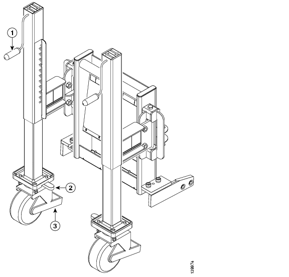
This section describes how to unpack the dolly (see Figure 1) used to move the unpacked LCC.
Figure 1 Chassis Dolly—90-Degree Position
Prerequisites
No prerequisites exist for this task.
Required Tools and Equipment
You need the following tools to perform this task:
•
•
Steps
To unpack the dolly, follow these steps:
Step 1
Step 2
Step 3
Step 4
Step 5
Caution
What to Do Next
After performing this task, unpack the chassis. See the "Unpacking the Chassis" section for more information.
Unpacking the Chassis
This section describes how to unpack the LCC.
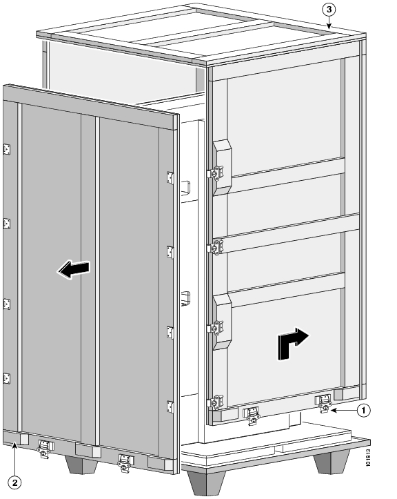
Caution
The chassis is shipped on a pallet by itself and arrives inside a polyethylene bag enclosed in a plywood box, held in place by steel clips (see Figure 2).
Figure 2 Line Card Chassis in Original Packaging
Prerequisites
Before performing this task, be sure to have sufficient room around the chassis pallet for unpacking.
Required Tools and Equipment
You need a 10-mm wrench to perform this task.
Steps
To unpack the chassis, follow these steps:
Step 1
Note
Caution
Step 2
Step 3
Step 4
Note
Note
Step 5
Step 6
Note
What to Do Next
After performing this task, you must attach the dolly to the chassis (see the "Attaching the Dolly to the Chassis" section).
Attaching the Dolly to the Chassis
This section describes how to attach the dolly (see Figure 3) to the LCC to prepare for removing the chassis shipping pallet and moving the chassis into place.
Figure 3 Chassis Dolly—90-Degree Position
Prerequisites
Before performing this task, unpack the chassis, unpack the dolly, and remove the chassis base cosmetic corner covers. See the "Unpacking the Chassis" section, and the "Unpacking the Dolly" section for more information.
Required Tools and Equipment
You need the following tools and part to perform this task:
•
•
•
•
Steps
To attach the dolly to the chassis, follow these steps:
Step 1
Step 2
Note
Step 3
Step 4
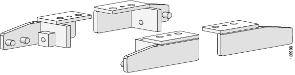
Note
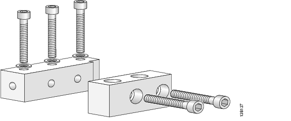
Figure 4 LCC Clamp Plates
Step 5
Step 6
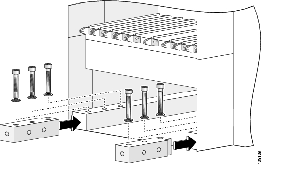
Figure 5 Attaching the Clamp Plates to the Chassis (Oblique View)
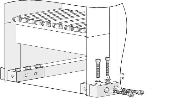
Figure 6 Attaching the Clamp Plates to the Chassis (Top View)
Step 7
Step 8
Step 9
Note
Step 10
Step 11
Step 12
Figure 7 Aligning and Attaching the Dolly to the Clamp Plates
Step 13
Step 14
What to Do Next
After performing this task, remove the shipping pallet from the chassis. See the "Removing the Chassis Shipping Pallet" section for more information.
Removing the Chassis Shipping Pallet
This section describes how to remove the chassis shipping pallet to prepare for moving the LCC into place.
Prerequisites
Before performing this task, unpack the chassis, unpack the dolly, and attach the dolly to the chassis. See the "Unpacking the Chassis" section, the "Unpacking the Dolly" section, and the "Attaching the Dolly to the Chassis" section for more information.
Required Tools and Equipment
No tools and equipment are required for this task.
Steps
To remove the shipping pallet from the chassis, follow these steps:
Step 1
Step 2
Step 3
Note
Step 4
Note
Step 5
Warning
What to Do Next
After performing this task, you may unpack the other pallets and move the chassis. See the "Unpacking the Other Pallets" section and the "Moving the Chassis" section.
Unpacking the Other Pallets
This section describes how to unpack the primary, secondary, power, and cosmetic pallets for the LCC.
Prerequisites
No prerequisites exist for this task.
Required Tools and Equipment
You need the following tools to perform this task:
•
•
•
Steps
To unpack the pallets, follow these steps:
Step 1
Note
Step 2
Step 3
Note
Step 4
Note
Note
Step 5
Step 6
Note
Note
What to Do Next
After performing this task, you may move the chassis (see the "Moving the Chassis" section).
Moving the Chassis
This section presents the following topics:
•
•
•
Dolly and Chassis Moving Guidelines
When you use the dolly or move the LCC, follow these guidelines:
•
•
–
–
–
•
–
–
–
–
–
–
•
–
–
–
–
–
•
–
–
–
–
–
–
–
•
–
–
–
–
–
Warning
Warning
Warning
Warning
Warning
Warning
Note
Caution
Verifying the Move Path
Before moving the chassis, it is critical that you verify that the path that you are planning to use to move the chassis to its final location can accommodate the chassis size and weight and the restrictions of the chassis when using the dolly (see the "Dolly Specifications" section).
See Table 5 for a list of the restrictions for your move path, and verify that you have sufficient room for the entire move path prior to moving the chassis.
Note
Verifying the Securing Location
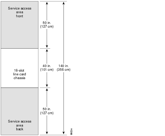
The chassis requires that you have a reasonable amount of space both in front and behind the chassis for sufficient airflow and the installation and removal of components. Allowing the recommended space also ensures that you have enough space available to perform the initial installation of the chassis and its components. Figure 8 shows a typical site floor plan.
Figure 8 Line Card Chassis Floor Plan
Before moving the chassis into position, make sure that you have properly prepared the site so that there is sufficient room for installation and maintenance.
For additional details on making your site ready for the chassis, see Cisco CRS-1 Carrier Routing System 16-Slot Line Card Chassis Site Planning Guide and Cisco CRS-1 Carrier Routing System Multishelf System Site Planning Guide.
Modifying the Dolly Configuration to Move the Chassis
This section describes how to modify the dolly from one configuration to another if your site requires it. The dolly can be configured in either the 180- or 90-degree position, depending on the needs of your site. For further information on the two configurations, see the "Dolly Specifications" section. See the "Dolly and Chassis Moving Guidelines" section section for important recommendations before modifying the dolly configuration.
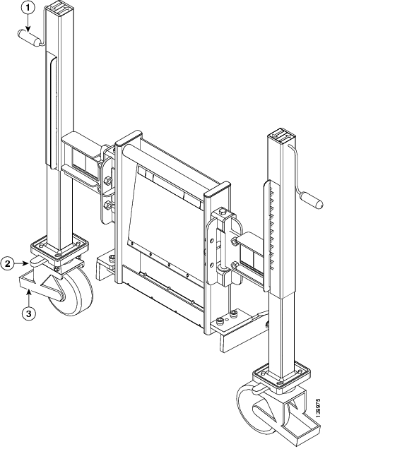
The dolly arrives in the 90-degree configuration, shown in Figure 9. ( Figure 9 shows the dolly with the LCC clamp plates installed.)
Figure 9 Chassis Dolly (90-Degree Position)
Prerequisites
Before performing this task, unpack the chassis, unpack the dolly, attach the dolly to the chassis, and remove the chassis from the shipping pallet. See the "Unpacking the Chassis" section, the "Unpacking the Dolly" section, the "Attaching the Dolly to the Chassis" section, and the "Removing the Chassis Shipping Pallet" section for more information.
Required Tools and Equipment
You need a 12-mm Allen wrench to perform this task.
Steps
To change the dolly configuration from the as-shipped 90-degree configuration to the preferred 180-degree transport configuration, follow these steps:
Step 1
Step 2
Step 3
Step 4
Step 5
Step 6
Step 7
Figure 10 Chassis Dolly—180-Degree Position
Step 8
Step 9
Step 10
Note
What to Do Next
After the dolly is in the correct configuration for your transport needs, you can move the chassis (see the "Moving the Chassis" section for more information). See the "Dolly and Chassis Moving Guidelines" section section for important recommendations before moving the chassis.
Moving the Chassis
This section describes how to move the unpacked LCC.
Note
Note
Prerequisites
Before performing this task, unpack the chassis, unpack the dolly, attach the dolly to the chassis, remove the pallet from chassis, and modify the dolly configuration (if necessary). See the "Unpacking the Chassis" section, the "Unpacking the Dolly" section, the "Attaching the Dolly to the Chassis" section, the "Removing the Chassis Shipping Pallet" section, and the "Modifying the Dolly Configuration to Move the Chassis" section for more information.
Required Tools and Equipment
You need the dolly (Cisco product number CRS-16-LIFT/B=) to perform this task.
Steps
To move the unpacked chassis, follow these steps:
Step 1
Step 2
Note
Caution
Note
Note
Step 3
Note
Step 4
Step 5
Note
What to Do Next
After performing this task, secure the chassis. See the "Securing the Chassis" section for more information.
Warning
Securing the Chassis
This section presents the following topics:
•
Site Preparation
Before moving the chassis into place and securing it, you must make sure that your site is prepared. Because of its size, weight, and EMI issues, the chassis must be securely bolted to the floor. Several possible bolting configurations exist for the chassis, including using the optional outrigger kit. Bolt hole templates are provided for the various securing options.
For complete details on preparing your site for the chassis, see Cisco CRS-1 Carrier Routing System 16-Slot Line Card Chassis Site Planning Guide.
Bolt Hole Templates
Cisco provides two bolt hole layout templates to help you determine where to install the system:
•
•
Complete information about the templates and floor plans, clearance information, and planning for future space needs, is included in Cisco CRS-1 Carrier Routing System 16-Slot Line Card Chassis Site Planning Guide.
Installing the Outrigger Kit
This section describes how to attach the outrigger kit (see Figure 11) to the LCC. The kit allows you to mount the chassis to the floor by providing offset holes for mounting. Primary and secondary bolt locations exist for securing the chassis to the floor. The drill hole template that is shipped with the chassis has two locations available for bolting the chassis the floor; the outrigger kit is needed if your site is such that you cannot bolt the chassis at the primary or secondary location. See Cisco CRS-1 Carrier Routing System Multishelf System Site Planning Guide for further details.
Figure 11 Outrigger Kit
Prerequisites
Before performing this task, you must prepare the floor, unpack the chassis, and move the chassis into position. See the "Unpacking the Chassis" section, the "Moving the Chassis" section, and the LCC sections of Cisco CRS-1 Carrier Routing System Multishelf System Site Planning Guide.
Note
Required Tools and Equipment
You need the following tools and part to perform this task:
•
•
•
•
•
Steps
To install an outrigger kit, follow these steps:
Step 1
Step 2
Step 3
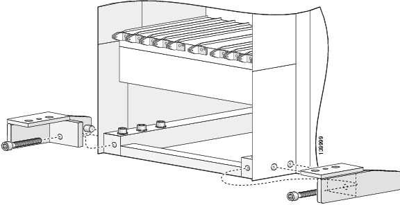
Step 4
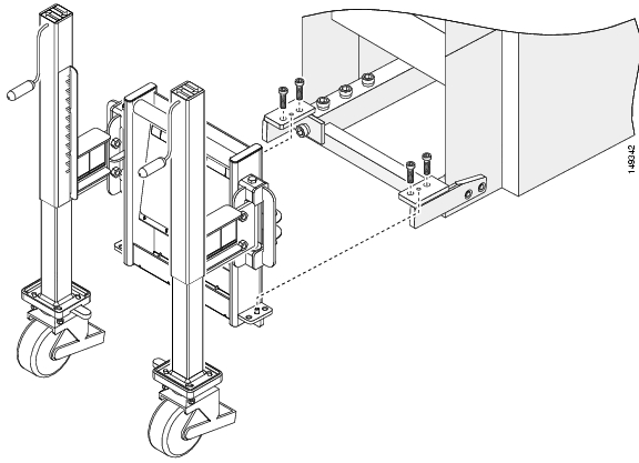
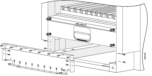
Figure 12 Inserting the Front (PLIM) Side Outrigger Interior Chassis Bolt Brackets
Step 5
Step 6
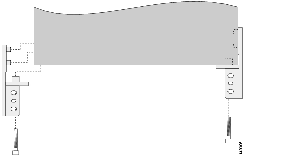
Figure 13 Attaching the Exterior Outrigger Brackets
Step 7
Step 8
Step 9
Step 10
Figure 14 Removing the Rear (MSC) Side Lower Chassis Cover Plate
Step 11
Step 12
Step 13
Step 14
Step 15
Step 16
Step 17
What to Do Next
After attaching the outrigger kit, you may secure the chassis to the floor. See the "Securing the Chassis" section.
Securing the Chassis
This section describes how to secure the LCC to a concrete floor. The chassis is shipped with a drill hole template to assist you in putting the bolts in the proper position on the floor.
Note
The instructions in this section are specific to securing the chassis to a concrete floor. The instructions for securing the chassis to a raised floor vary from site to site, depending on such details as whether your floor needs additional support, where (depending on the location of the floor tiles) the bolt holes need to be, and so on. Work with your vendor to determine your needs for your particular site.
Prerequisites
Before performing this task, you must use the drill template to prepare the floor, unpack the chassis, and move the chassis into position. See the "Unpacking the Chassis" section, the "Moving the Chassis" section, and the LCC sections of Cisco CRS-1 Carrier Routing System Multishelf System Site Planning Guide.
Required Tools and Equipment
You need the following parts to perform this task:
•
•
Note
Steps
To secure the chassis, follow these steps:
Step 1
Step 2
Step 3
Step 4
Note
Step 5
Step 6
Note
Caution
Step 7
Step 8
Step 9
What to Do Next
After performing this task, you need to unpack and install all remaining chassis parts. See the "Unpacking the Other Pallets" section for unpacking information and Installing the Cisco CRS-1 Carrier Routing System 16-Slot Line Card Chassis to locate the installation instructions for the individual parts.
Component Return Information
Before preparing to ship back the product or product components, you must contact Cisco technical support and provide them with the details of your difficulty. Technical support needs to confirm your product or component failure prior to assigning a RMA number for return shipment. For additional information. see the "Obtaining Technical Assistance" section.
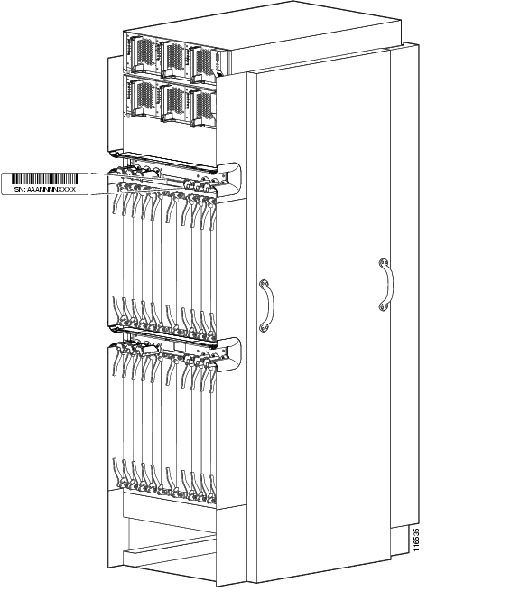
To facilitate your conversation with technical support, locate and note the serial number for the chassis. The serial number label for the LCC is located on the front (PLIM) side, between the upper PLIM card slots and cable management bracket (see Figure 15).
Figure 15 Cisco CRS-1 16-Slot Line Card Chassis Serial Number Location
![]()
![]()
![]()
![]()
![]()
![]()
![]()
![]()
Posted: Mon Oct 2 12:16:51 PDT 2006
All contents are Copyright © 1992--2006 Cisco Systems, Inc. All rights reserved.
Important Notices and Privacy Statement.