|
|

The procedures for installing the Cisco ONS 15194 are presented in the following sections:
After you prepare the area for installation and verify that all equipment is present, you can proceed with the ONS 15194 installation.
 |
Caution To prevent ESD damage, use an ESD wrist strap when you unpack and install ONS 15194 components. |
 |
Warning Only trained and qualified personnel should be allowed to install, replace, or service this equipment. |
You must install the ONS 15194 in a rack. The ONS 15194 is not designed to be installed as a shelf-mounted or a free-standing system. To install the ONS 15194 chassis into a rack mount, do the following:
Step 1 Open the rack-mount installation kit containing the paper stencil and eight nuts, bolts, and washers.
Step 3 Insert a nut from the back of the rack toward the front (so that the bolt can be screwed into the nut from the front of the rack) at the location of each of the eight marked holes.
Step 4 Lift the Cisco ONS 15194 up to the location of the nuts and have a second person screw in two of the bolts (one on each side) with the washers placed between the bolt and the ONS 15194 panel.
|
Warning Two people are required to lift the chassis. To prevent injury, keep your back straight and lift with your legs, not your back. |
Step 5 When the ONS 15194 is in place with one bolt on each side, screw in the other six bolts to secure the chassis on the rack.
When the chassis is secure in the rack, you can install the remaining line and switch cards into the ONS 15194. Possible cards and their respective slots in the ONS 15194 chassis are outlined in Figure 3-1. Inserting and removing ONS 15194 components are covered in the following sections:
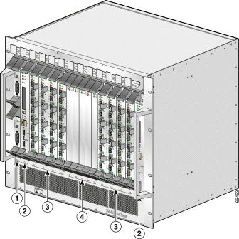
| 1 | PEM cards | 3 | Line cards (L1 to L8) |
| 2 | Controller cards (C1, C2) | 4 | Switch cards (S1 to S5) |
Open one card from its original packing. Keep unused cards in their original packing until use. Remove the blank card from the slot where the card is to be inserted and insert the card into the empty slot.
To insert a card into the chassis, do the following:
Step 1 Gently push the card into the slot until it is inserted into the backplane.
Step 2 Press inward on the two black handles, toward the center of the card, to lock the card in place.
Step 3 Screw the card in place on the top and bottom.
Continue to install all necessary line and switch cards into the chassis. Leave blank cards in any unused slots.
|
Caution Make sure that all cards are inserted completely into the backplane, because partially inserted card may cause unexpected behavior. |
To remove a card from the chassis, do the following:
Step 1 Unscrew the card from the chassis (one screw each on the top and bottom of the card).
Step 2 Press outward on the two black handles, toward the top and bottom of the card, respectively.
Step 3 Gently pull the card out of the slot.
Store any unused cards in their original packing.
Before powering up the ONS 15194, take note of the following safety warnings:
|
Warning The DC supply source is to be located within the same premises as this equipment. |
|
Warning This equipment shall be connected directly to the DC supply system earthing electrode conductor or to a bonding jumper from an earthing terminal bar or bus to which the DC supply system earthing electrode is connected. |
|
Warning This equipment shall be located in the same immediate area (such as, adjacent cabinets) as any other equipment that has a connection between the earthed conductor of the same DC supply circuit and the earthing conductor, and also the point of earthing of the DC system. The DC system shall not be earthed elsewhere. |
|
Warning There shall be no switching or disconnecting devices in the earthed circuit conductor between the DC source and the point of connection of the earthing electrode conductor. |
|
Warning Connect the unit only to a 48 Volt DC power source that complies with the Safety Extra-Low Voltage (SELV) requirements in IEC 60950 based safety standards. |
|
Warning This equipment needs to be grounded. Ensure that the ONS 15194 is connected to earth ground during normal use. |
When all necessary cards are installed into the chassis, power up the ONS 15194 as follows:
Step 1 Connect one or both PEM cards to an electrical power source. This may be a DC power source.
Step 2 Power up each of the PEM cards using the On/Off switch. The PWR LED should go on (green) immediately.
Step 3 Verify that the controller card PWR LED is on. If it is not on, verify that there is power to the ONS 15194. Initially, the FAIL LED will be on. Approximately 30 seconds after power up, the FAIL LED should turn off. The ACT LED should begin to flash once per second. The standby controller card ACT LED should flash once per 3 seconds.
Step 4 Verify that the line and switch cards PWR LED is on. The ACT LED should flash fast for 3 to 4 seconds and then, as it becomes synchronized with the active controller card, it should flash once per second. The FAIL LED will initially go on for 3 to 4 seconds, after which it should turn off.
|
Warning This unit might have more than one power supply connection. All connections need to be removed to de-energize the unit. |
Cable connections are presented in the following sections:
Fiber-optic cable connections depend on the type of device being connected and the configuration of the ONS 15194. Possible scenarios are presented in the following sections:
When an interface is correctly connected to functional equipment, the respective CARRIER LED on the line card should go on. Verify the corresponding link connectivity indication on the router interface card.
Connect each SRP/DPT node as shown in Figure 3-2.
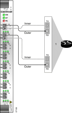
Two ONS 15194s can operate in an "inner-outer" fiber topology by connecting all inner SRP ring fibers to one ONS 15194 and all outer SRP ring fibers to another ONS 15194. Such a connection, in conjunction with the SRR protocol on the SRP nodes, provides ONS 15194 system redundancy. In this scenario, the Tx/Rx connector pair of the node is connected to different ONS 15194s. Connect both inner fibers of a node to the same connector pair in one ONS 15194 chassis and both outer fibers of the node to the same connector pair in a second ONS 15194 chassis as shown in Figure 3-3.
 |
Note In order for two ONS 15194s to work together and provide system redundancy, all routers/devices in the ring must support the single ring redundancy (SRR) functionality. SRR is supported in IOS Releases 12.0(16)S and subsequent S releases. |
Connect each POS node to a single port. Connect automatic protection switching (APS) nodes to two separate interfaces, one for working and one for protection. The working and protection links for the ONS 15194 must correspond to the working and protection connections on the routers.
When the software is running, only the interface of the active controller card is operational. Because of this, only one IP address needs to be configured for the ONS 15194, which is always used by the currently active controller card.
|
Caution If two controller cards are installed in the ONS 15194, but only one is connected to a hub or switch, you will loose all IP connectivity if the controller card is reloaded. |
|
Warning The ports labeled "Eth," "Console," "Maint," and "PCMCIA" are safety extra-low voltage (SELV) circuits. SELV circuits should only be connected to other SELV circuits. Avoid connecting the SELV circuits to the telephone network voltage (TNV) circuits." |
|
Note Before the ONS 15194 can be accessed via Ethernet, you must configure the networking parameters using a direct serial connection to the active controller card. See "Configuring Network Parameters" in the chapter "Configuring the ONS 15194." |
Connect the RS-232C serial cable between the CONSOLE connector on one of the controller cards and the COM port on your PC. The CONSOLE port controls the active controller card in the ONS 15194, even if it is connected via the standby controller card.
|
Warning The ports labeled "Eth," "Console," "Maint," and "PCMCIA" are safety extra-low voltage (SELV) circuits. SELV circuits should only be connected to other SELV circuits. Avoid connecting the SELV circuits to the telephone network voltage (TNV) circuits." |
|
Caution You can connect to only one of the controller cards using the CONSOLE port at any one time. A concurrent connection to the CONSOLE port on two controller cards causes the port to malfunction. |
The MAINT connector should only used in the following instances:
|
Caution Do not leave the UART password key plugged into the MAINT port. In addition to being a security hazard, the software will not run if the ONS 15194 is powered down and powered back up again. |
You should not have a permanent connection to this serial interface.
The default RS-232C connection parameters are 9600 bps, no parity, and no flow control.
Step 1 Unscrew all screws holding the fan tray grid on the lower front of the ONS 15194.
Step 2 Remove the fan tray grid.
Step 3 Gently pull the fan tray out of the chassis.
Step 4 Slide the replacement fan tray into place.
Step 5 Replace the fan tray grid and replace the screws.
|
Caution Do not leave the fan tray out of the ONS 15194 for more than 2 minutes while the ONS 15194 is operational to avoid over-heating the system. |
![]()
![]()
![]()
![]()
![]()
![]()
![]()
![]()
Posted: Sun Oct 6 02:21:18 PDT 2002
All contents are Copyright © 1992--2002 Cisco Systems, Inc. All rights reserved.
Important Notices and Privacy Statement.
