|
|

Table Of Contents
Cisco Supervisor Engine Cisco IOS Software
Cisco Supervisor Engine Software Releases
Bulk MWAM Configuration Storage on Cisco Supervisor Engine Boot Flash
Using the Remote Console for MWAMs
Remote Console Support for the PC
Performing the Inline Cisco IOS Image Upgrades from AP
VLANs over IP Unnumbered Interfaces
IEEE 802.1Q-in-Q VLAN Tag Termination
Software and Hardware Requirements
Cisco Supervisor Image Prerequisite
Reverting to Previous IOS Image
MWAM Processor Naming Conventions
Configuring MWAM VLANs on the Cisco Supervisor Engine
Configuring Layer 3 Interfaces on VLANs
Establishing Processor Session to Configure Application
IOS Command Restrictions at the Processor Level
Configuring a LAN Port for Layer 2 Switching
Configuring Subinterfaces on an MWAM Processor
Verifying the MWAM Configuration
Configuring Remote Console and Logging
Clearing MWAM Session from Supervisor Console
Recovering from MWAM Processor Lockout
Processor Control (PC) Commands
Determining the MWAM Cisco IOS Image Name
Maximum Buffer Allocation for Complex 0 CPUs
Logging Into a Processor Complex.
CrashInfo and Crashdump Error Messages
Boot Flash Memory Error Message
Obtaining Technical Assistance
Obtaining Additional Publications and Information
Cisco Multiprocessor WAN Application Module Installation and Configuration Notes for the Cisco 7600 Series Internet Router
Product number: WS-SVC-MWAM-1
The Cisco Multiprocessor WAN Application Module (MWAM) is a Cisco IOS software application module that you can install into the Cisco 7600 Series Internet Routers. The module allows you to run multiple instances of Cisco Ethernet Service Aggregation applications.
The MWAM system currently includes the following Cisco services:
•
Service Selection Gateway (SSG)
•
•
•
•
•
This document describes how to install and configure the MWAM software and hardware.
Contents
Software and Hardware Requirements
Obtaining Technical Assistance
Obtaining Additional Publications and Information
MWAM Hardware Overview
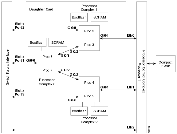
Each Cisco Multiprocessor WAN Application Module (MWAM) card contains three processor complexes, with two CPUs each ( Figure 1). The CPUs share a common IOS image but each runs independently of the others so that there are six unique Cisco IOS software instances running simultaneously. These Cisco IOS instances use gigabit Ethernet 802.1Q trunk port interfaces to carry VLAN encapsulated traffic to and from the network through the Cisco 7600 switching hardware. Each processor complex (housing two Cisco IOS instances) shares one gigabit Ethernet interface.
Figure 1 MWAM Card
Currently, an MWAM card running SSG or LNS can run up to six instances of Cisco IOS software simultaneously. Each MWAM card is dedicated to run one function, SSG or LNS. The Cisco 7600 chassis can house up to four MWAM cards.
Processor Complexes
The daughter card has three processor complexes with two processors on each complex. Each of the processors can run one Cisco IOS application image. Table 1 shows the mapping between MWAM processors and complexes, as well as other important information about the processors on the MWAM.
Table 1 MWAM Processor Matrix
1
Processor Control (PC)
—
2
1
1 Gigabyte
Gi 0/0
Slot x, port 2
3
4
2
1 Gigabyte
Gi 0/0
Slot x, port 3
5
6
0
512 Mbyte
Gi 0/0
Slot x, port 1
71
1 Processor 7 is disabled for use by most applications because processors 6 and 7 would be sharing the smaller memory size on processor complex 0.
Currently, an MWAM can run five instances (mobile wireless) or six instances (broadband) of Cisco IOS software simultaneously (depending on the Cisco IOS application that is purchased). Each MWAM has one IOS application image. All processors on the MWAM are loaded with the same image. Mixed applications (for example, PDSN, GGSN, and SSG) on the same MWAM are not supported. The Catalyst 6500 chassis and Cisco 7600 chassis can accommodate multiple MWAMs. Therefore, multiple applications could run in the same chassis on different MWAMs.
Memory
Each processor complex (except processor complex 0) is allocated 1 GB of memory. Processor complex 0 has only 1 memory slot, which provides a 512 MB memory module. Depending on the application purchased, the 512 MB of memory is either shared by both processors in complex 0 or reserved for only one processor in the complex (the other processor being disabled).
Boot Flash Memory
Each processor complex has boot flash memory that it uses to store Cisco IOS configurations, failure information, Read Only Memory for Monitor (ROMMON) images, and variables for both processors. The 8 MB boot flash memory is partitioned as follows:
•
•
•
•
•
•
Caution
Both processors on a processor complex share the same physical boot flash memory. However, each processor has its own partition. If you list the directory of each processor, you observe that even though the processors share the same boot flash memory, the contents of each directory are unique. For example:
proc2# dirDirectory of bootflash:/No files in directory524288 bytes total (524288 bytes free)proc2#proc3# dirDirectory of bootflash:/0 -rw- 1897 Jun 13 2003 22:25:41 running-config1 -rw- 1897 Jun 14 2003 03:54:35 running-2524288 bytes total (520110 bytes free)
Note
Compact Flash
The compact flash (cf) card is a component of the Processor Control (PC) Complex.
Table 2 lists the partitions configured on the compact flash card.
Table 2 Compact Flash Partitions1
1
16
Maintenance (boot partition)
2
1
Maintenance
3
7
Maintenance
4
100
Application (extended/boot partition)
5
16
Application (root partition)
6
48
Application (Cisco IOS image partition)
7
36
Application (logging/debugging partition)
1 Partitions, sizes, and descriptions listed here are introduced with Cisco IOS Release 12.3(5)B. Before this release, only six partitions were configured and sizes for the Application Partition were different from the values listed here.
Gigabit Ethernet Interfaces
Each processor complex shares one Gigabit Ethernet link to the switching fabric on the Cisco 7600 router. Gigabit Ethernet links to the switching fabric perform as 802.1q trunks. Additional Gigabit Ethernet interfaces provide internal connections between the processor complexes and to the processor control complex.
Each of the three MWAM processor complexes uses one Gigabit Ethernet interface (Gi0/0) that maps to the three Gigabit Ethernet interfaces referred to as the supervisor engine (see Figure 1). Therefore, two processors on each processor complex share a single Gigabit Ethernet interface. Each processor interface can be configured with multiple subinterfaces as required by the application.
Cisco MWAM Software Overview
The Cisco MWAM requires two software components for its operation:
•
Note
•
Cisco Supervisor Engine Cisco IOS Software
The first software component is the Cisco IOS image on the Supervisor Engine 2, Supervisor Engine 720, and Supervisor Engine 720 with PFC3BXL. This image on the supervisor module recognizes and initializes the MWAM and its processors. You must use a Cisco IOS release that supports the MWAM: Release 12.2(18)SXD1 or later.
Note
MWAM Software Bundle
The MWAM software resides in the compact flash (cf) card that is integrated with the PC complex:
•
•
You can upgrade the MWAM software on the compact flash card through the Cisco supervisor engine. The upgrade process downloads the latest versions of the AP and MP images from the Cisco Software Center to the compact flash card.
The standard process involves booting the daughter card from the MP partition, copying the AP image to the compact flash card, then resetting the daughter card to the AP partition. Then, from the AP partition, you copy the MP image to the compact flash card. An inline Cisco IOS image upgrade procedure is provided. See the "Standard Upgrade Procedures" section for more information about these procedures.
The application processors (2-6) boot from processor 1. All processors run the same Cisco IOS application image.
Supported Applications
The MWAM supports the following applications:
•
•
•
•
•
•
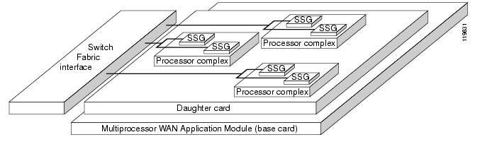
The MWAM architecture allows six broadband applications to reside on a single MWAM. Figure 2 shows an example of six SSGs on one module. Each Cisco Catalyst 6500 or Cisco 7600 chassis can be populated with multiple MWAMs. Therefore, a chassis with three MWAMs can support 18 SSGs.
Figure 2 Example of SSG Application on MWAM
Application Releases
Tip
For release notes and feature module descriptions of the applications that are supported on the MWAM, and for detailed information about the Cisco SSG or LNS, see the Cisco publications at the following URLs:
Cisco SSG
http://www.cisco.com/univercd/cc/td/doc/product/software/ios122/122newft/122t/122t8/ft_ssg8t.htm
Cisco LNS
http://www.cisco.com/univercd/cc/td/doc/product/software/ios122/122newft/122t/122t8/ft_ssg8t.htm
Layer 2 Access Concentration (LAC)
http://www.cisco.com/univercd/cc/td/doc/product/software/ios122/122newft/122t/122t8/ft_ssg8t.htm
L2TP out PPP Termination Aggregation (PTA)
http://www.cisco.com/univercd/cc/td/doc/product/software/ios122/122newft/122t/122t8/ft_ssg8t.htm
NBAR
http://www.cisco.com/univercd/cc/td/doc/product/software/ios122/122newft/122t/122t8/dtnbarad.htm
CBAC
Cisco Supervisor Engine Software Releases
Tip
For information about the Cisco supervisor engine image that supports the applications on the MWAM, see the Cisco publications at the following URLs:
http://www.cisco.com/en/US/products/sw/iosswrel/ps5012/prod_release_note09186a0080145494.html
http://www.cisco.com/univercd/cc/td/doc/product/lan/cat6000/122sx/ol_4164.htm
Cisco MWAM Module Features
The Cisco MWAM module provides the features listed in Table 3. The table lists, where applicable, supervisor engine IOS image requirements and MWAM IOS image requirements.
Bulk MWAM Configuration Storage on Cisco Supervisor Engine Boot Flash
Note
You can store configuration files for MWAM processors in either of the following locations:
•
•
Storing in Local Mode
The MWAM provides local storage of Cisco IOS configurations in NVRAM. However, if a fully configured MWAM requires replacement, the operator must perform the following tasks:
1.
2.
3.
4.
This replacement scenario requires time-consuming intervention by the operator. To reduce operator intervention, you can configure the MWAM to provide supervisor (boot flash) storage instead of local (NVRAM) storage of configuration files.
Storing in Supervisor Mode
Supervisor storage mode allows MWAM configuration files to be stored in the supervisor boot flash. This mode allows centralized management of all MWAM configuration files. In supervisor mode, when an MWAM is replaced, all processors on the MWAM automatically load their configuration files from the supervisor boot flash. No configuration files are contained locally in NVRAM.
The supervisor module verifies that its boot flash contains a properly named configuration file for each MWAM processor. The following naming convention is used:
SLOTxPCy.cfgThe variable x represents the MWAM slot number and y represents the processor number. For example, SLOT6PC3.cfg is the configuration file for processor 3 on the MWAM in slot 6.
The following example shows the display of MWAM configuration files on the supervisor module:
ce-cat6k-1# dir bootflash:Directory of bootflash:/1 -rw- 1733412 May 28 2002 18:59:10 c6msfc2-boot-mz.121-11b.E2 -rw- 11280364 May 28 2002 18:59:22 c6msfc2-psv-mz.121-11b.E.bin73 -rw- 42 Jun 24 2003 22:24:31 SLOT4PC7.cfg74 -rw- 2876 Jun 24 2003 22:24:32 SLOT6PC2.cfg75 -rw- 42 Jun 24 2003 22:24:32 SLOT6PC3.cfg79 -rw- 482 Jun 24 2003 22:24:34 SLOT6PC7.cfg85 -rw- 2747 Jul 01 2003 19:56:02 SLOT6PC6.cfg86 -rw- 450 Jul 01 2003 19:58:04 SLOT4PC2.cfg87 -rw- 450 Jul 01 2003 19:58:47 SLOT4PC3.cfg89 -rw- 450 Jul 01 2003 20:02:25 SLOT4PC4.cfg90 -rw- 450 Jul 01 2003 20:03:30 SLOT4PC5.cfg91 -rw- 450 Jul 01 2003 20:04:13 SLOT4PC6.cfg107 -rw- 455 Jul 16 2003 11:31:50 SLOT6PC5.cfg109 -rw- 505 Jul 25 2003 08:43:55 SLOT6PC4.cfgIf a standby (slave) supervisor is installed, the slave boot flash stores backups of the MWAM configuration files that are on the master supervisor. If a difference is detected between corresponding files on the active and standby supervisor modules, the file on the boot flash is copied over the file on the slave boot flash. This compare and copy operation occurs after MWAM replacement or when the active supervisor module detects that a standby supervisor module is installed.
When operating in supervisor mode, the NVRAM on the MWAM does not keep a backup configuration file. Instead, the backup files for MWAM configurations are stored on the standby supervisor. The following example shows the display of MWAM configuration files on the standby supervisor module:
ce-cat6k-1# dir slavebootflash:Directory of slavebootflash:/1 -rw- 1693168 May 08 2003 02:18:54 c6msfc2-boot-mz.121-8a.EX2 -rw- 27411228 May 28 2003 19:39:52 c6k222-jsv-mz.122-14.ZA1.bin877 -rw- 450 Jul 25 2003 08:26:41 SLOT4PC2.cfg878 -rw- 450 Jul 25 2003 08:26:42 SLOT4PC3.cfg879 -rw- 450 Jul 25 2003 08:26:42 SLOT4PC4.cfg880 -rw- 450 Jul 25 2003 08:26:43 SLOT4PC5.cfg881 -rw- 450 Jul 25 2003 08:26:44 SLOT4PC6.cfg882 -rw- 42 Jul 25 2003 08:26:44 SLOT4PC7.cfg883 -rw- 2876 Jul 25 2003 08:26:45 SLOT6PC2.cfg884 -rw- 42 Jul 25 2003 08:26:46 SLOT6PC3.cfg886 -rw- 455 Jul 25 2003 08:26:47 SLOT6PC5.cfg887 -rw- 2747 Jul 25 2003 08:26:48 SLOT6PC6.cfg888 -rw- 482 Jul 25 2003 08:26:49 SLOT6PC7.cfg889 -rw- 505 Jul 25 2003 08:43:36 SLOT6PC4.cfg
Caution
Note
The following commands are provided for storage mode configuration:
•
•
[local|supervisor]•
See the "Command Reference" section for syntax and usage guidelines.
Note
Using the Remote Console for MWAMs
Note
The remote console for MWAMs allows operators to use the existing supervisor console as a single connection point to control debugging, display show commands, and view logging output for all MWAM processors in the chassis. The remote console has three related components:
•
•
•
The User Data Protocol (UDP) transports the remote console commands, VTY output, and logging information. Initially, the traffic flows through the Processor Control Complex, which allows logging information to be relayed to the supervisor module before the MWAM processors have been configured. When the MWAM processors are configured, the traffic can continue to be transmitted through the Processor Control Complex, or it can be redirected to the switching fabric using a configuration command on the MWAM processor.
Unified Command Operations
The remote console provides a mechanism to execute supported commands on a specified MWAM processor in the chassis. The targeted processor receives the command through a registered UDP port, reassigns its VTY to the remote VTY, and executes the command. When the command operation completes, the VTY is restored.
The supported commands for unified operation from the remote console are listed in Table 4.
The mechanism for unified command operation is provided in the following command:
execute-on slot processor commandThe slot and processor variables represent the MWAM slot and processor numbers. The command variable can be any command in the unified command set listed in Table 4. Additional syntax and usage guidelines are provided in the "Command Reference" section.
Show and Debug Display
The remote VTY function directs output from executive level commands to the appropriate console. Commands that are received and processed by the MWAM processor are directed to a remote VTY process on the supervisor module. The remote VTY process directs the output to the supervisor level for either:
•
•
MWAM Logging to Console, Buffer, or Syslog
The MWAM's remote logging capability uses logging information from the MWAM logger process. When the MWAM attempts to log an event, the MWAM logger process invokes a list of destinations for the log. If the supervisor logger is enabled on the MWAM processor, then the log flows through the remote VTY and is processed by the supervisor. At the supervisor, the log can be directed to one or more of several destinations including console, buffer, or syslog.
Logs received by the supervisor are prefixed with information that identifies which processor generated the log. Examples of log messages follow.
Processor 5 on the MWAM in slot 6 generated the following error message:
MWAM 06/5: 00:02:05: %SNMP-5-MODULETRAP: Module 6 [Up] TrapProcessor 4 on the MWAM in slot 2 generated the following debug message:
MWAM 02/4: 00:03:42: ICMP: echo reply sent, src 10.10.10.2, dst 10.10.10.1Using the Log Option
When using the execute-on slot processor log show command, the volume of logging information can be large. Under these conditions, the console processing can load down the supervisor CPU.
To prevent overloading the console, two options are available:
1.
no logging console guaranteedThis configuration allows the output to be dropped when the console backs up.
2.
no logging console debugThis configuration directs the output to other logging endpoints such as buffer or SysLog.
Note
Example Usage
The following examples illustrate ways you can use the Remote Console and Logging feature to manage MWAM processors from the supervisor console.
Show Logs for All MWAM Processors
You can display logging information for all MWAM processors in a chassis with a single command from the supervisor console.
1.
2.
3.
Sup-7600# execute-on all all show loggingShow Image Version of All MWAM Processors
You can display the software release running on all MWAM processors in a chassis with a single command from the supervisor console. The following example illustrates this capability:
Sup-7600# execute-on all all show version----------- Slot 3/CPU 2, show ver-------------Cisco Internetwork Operating System SoftwareIOS (tm) MWAM Software (MWAM-G7IS-M), Experimental Version12.3(20031015:202420) [GGSN_R3_R4_1015_1 103]Copyright (c) 1986-2003 by cisco Systems, Inc.Compiled Wed 15-Oct-03 15:53 by testerImage text-base:0x20200D40, data-base:0x21168000ROM:System Bootstrap, Version 12.2(11r)YS1, RELEASE SOFTWARE (fc1)Router uptime is 2 days, 23 hours, 52 minutesSystem returned to ROM by power-onSystem restarted at 01:09:42 UTC Tue Oct 21 2003System image file is "svcmwam-g7is-mz.r3_r4-1015"Cisco MWAM (MWAM) processor with 473088K/32768K bytes of memory.SB-1 CPU at 700Mhz, Implementation 1, Rev 0.2Last reset from power-onBridging software.X.25 software, Version 3.0.0.1 Gigabit Ethernet/IEEE 802.3 interface(s)511K bytes of non-volatile configuration memory.Configuration register is 0x0----------- Slot 3/CPU 3, show ver-------------Cisco Internetwork Operating System SoftwareIOS (tm) MWAM Software (MWAM-G7IS-M), Experimental Version12.3(20031015:202420) [howang-GGSN_R3_R4_1015_1 103]Copyright (c) 1986-2003 by cisco Systems, Inc.Compiled Wed 15-Oct-03 15:53 by howangImage text-base:0x20200D40, data-base:0x21168000ROM:System Bootstrap, Version 12.2(11r)YS1, RELEASE SOFTWARE (fc1)Router uptime is 2 days, 23 hours, 52 minutesSystem returned to ROM by power-onSystem restarted at 01:10:19 UTC Tue Oct 21 2003System image file is "svcmwam-g7is-mz.r3_r4-1015"Cisco MWAM (MWAM) processor with 473088K/32768K bytes of memory.SB-1 CPU at 700Mhz, Implementation 1, Rev 0.2Last reset from power-onBridging software.X.25 software, Version 3.0.0.1 Gigabit Ethernet/IEEE 802.3 interface(s)511K bytes of non-volatile configuration memory.Configuration register is 0x0
Tip
Sup-7600#execute-on all all show version | include image
Remote Console Support for the PC
This feature is introduced with Cisco IOS release 12.3(5a)B.
Remote console support for the PC allows you to access the PC using the execute-on command. With this feature, you can execute Processor Control Commands from the Supervisor console; you do not have to session down to the PC. To enable remote console support for the PC, configure UDP port 4000 on the Supervisor and the MWAM processor (see Configuring Remote Console and Logging).
The supported commands for PC unified operation are listed in Table 5.
The mechanism for unified command operation is provided in the following command:
execute-on slot processor commandThe slot variable represents the MWAM slot and the processor variable is always 1 for the PC (see Table 1). The command variable can be any command in the PC unified command set listed in Table 5. Additional syntax and usage guidelines are provided in the Command Reference chapter.
Using Persistent Log Files
Logs are stored on the processor control complex. These logs can be used to help diagnose system failures. This feature is introduced with Cisco IOS Release 12.3(5)B.
Performing the Inline Cisco IOS Image Upgrades from AP
This feature is introduced with Cisco IOS Release 12.3(5)B.
The Inline Cisco IOS Image Upgrade is similar to the AP upgrade in that both procedures upgrade the image used by the application. However, you perform the inline Cisco IOS image upgrade from the AP, not the MP; therefore, you do not have to reset the module. This significantly reduces the amount of down time associated with module resets.
Note
VLANs over IP Unnumbered Interfaces
The VLANs over IP Unnumbered Interfaces feature allows IP unnumbered interface support to be configured on Ethernet virtual LAN (VLAN) subinterfaces. This feature also provides support for Dynamic Host Configuration Protocol (DHCP) on VLAN subinterfaces. Configuring Ethernet VLANs on IP unnumbered subinterfaces can save IPv4 address space, simplify configuration and address management, and simplify migration for DSL providers from ATM networks to IP. See http://www.cisco.com/en/US/products/sw/iosswrel/ps5207/products_feature_guide09186a00801d1dfd.html.
IEEE 802.1Q-in-Q VLAN Tag Termination
Encapsulating IEEE 802.1Q VLAN tags within 802.1Q enables service providers to use a single VLAN to support customers who have multiple VLANs. The IEEE 802.1Q-in-Q VLAN Tag Termination feature on the subinterface level preserves VLAN IDs and keeps traffic in different customer VLANs segregated.
This feature also includes RADIUS port identification for PPPoE over 802.1 O-in-Q. See http://www.cisco.com/en/US/products/sw/iosswrel/ps5207/products_feature_guide09186a00801f0f4a.html.
Software and Hardware Requirements
Supported Hardware
Before you can use the MWAM module, you must configure your network with a Cisco Supervisor Engine 2 with a Multilayer Switch Feature Card 2 (MSFC2) or a Supervisor Engine 720, and a module with ports to connect to server and client networks.
Software Requirements
Caution
Table 6 lists the required software versions for the supervisor engines.
Table 6 Cisco IOS Releases
Supervisor Engine 2 with an MSFC2
Supervisor Engine 720
•
•
For information on Cisco IOS Release 12.2(18)SXD1, see the Release Notes for Cisco IOS Release 12.2SX on the Catalyst 6500 and Cisco 7600 Supervisor Engine 720 and Supervisor Engine 2.
Front Panel Description
The MWAM module front panel ( Figure 3) includes a Status LED and a Shutdown button.
Figure 3 MWAM Front Panel
MWAM Status LED
The Status LED indicates the operating states of the module.
Table 7 lists the MWAM Status LEDs.
FIPS LED
The Federal Information Processing Standards (FIPS) LED is not currently used. It
Shutdown Button
Caution
You can shut down the module by entering the hw-module module <module slot number> shutdown command in privileged mode from the CLI at the supervisor engine.
If the MWAM module fails to respond to this command, shut down the module by using a small, pointed object (such as a paper clip) to access the Shutdown button on the front panel.
The shutdown procedure may require several minutes. The Status LED turns off when the module shuts down.
Safety Overview
Safety warnings appear throughout this publication in procedures that, if performed incorrectly, may harm you. A warning symbol precedes each warning statement.
Warning
Warning
Warning
Warning
Warning
Preparing to Install MWAMs
Before installing the MWAM, make sure that the following items are available:
•
•
Required Tools
This section describes the tools that you need to install the MWAM module.
Warning
Note
These tools are required to install the MWAM module into the Cisco 7600 series Internet routers:
•
•
•
Installing MWAMs
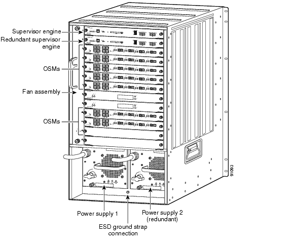
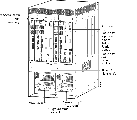
This section describes how to install the MWAM in the Cisco 7600 series Internet router. Make sure that you have an open slot available for the new module. Install the MWAMs as follows:
•
The slot numbering is the same in the 3-slot and 6-slot chassis ( Figure 4, Figure 5, and Figure 6)
•
The horizontal slots are numbered from top to bottom; the vertical slots are numbered from right to left.
In all chassis:
•
•
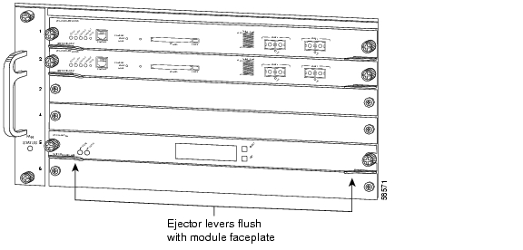
Figure 4 Cisco 7603 Internet Router Slot Numbers
Figure 5 Cisco 7606 Internet Router Slot Numbers
Figure 6 Cisco 7613 Internet Router Slot Numbers
Figure 7 Cisco 7609 Internet Router Slot Numbers
Caution
Warning
Warning
Warning
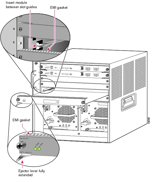
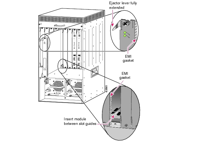
To install an MWAM in the Cisco 7600 series Internet router, perform these steps:
Step 1
Step 2
Step 3
This action ensures that the EMI gaskets on all modules are fully compressed to maximize the opening space for the new module or the replacement module.
Note
Step 4
Step 5
Step 6
Horizontal Slots
a.
b.
Figure 8 Positioning the Module in a Horizontal Slot Chassis
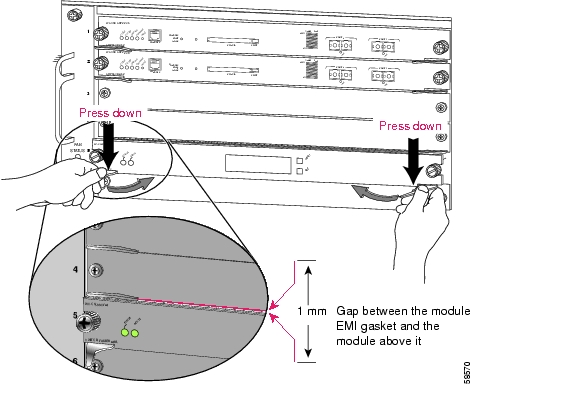
Figure 9 Clearing the EMI Gasket in a Horizontal Slot Chassis
c.
Caution
d.
Figure 10 Ejector Lever Closure in a Horizontal Slot Chassis
Note
e.
Note
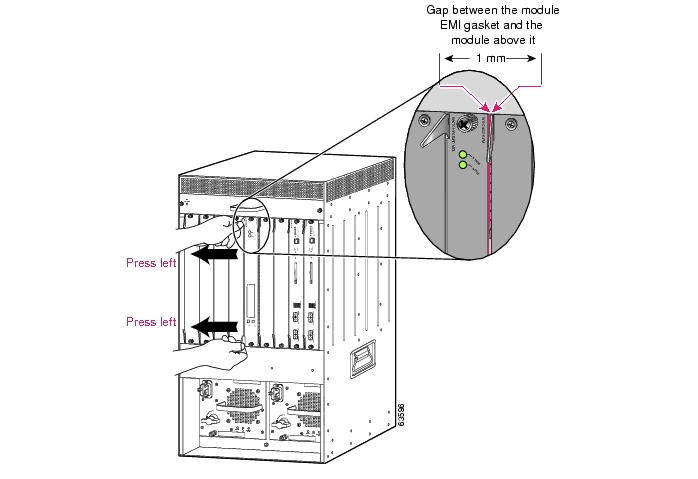
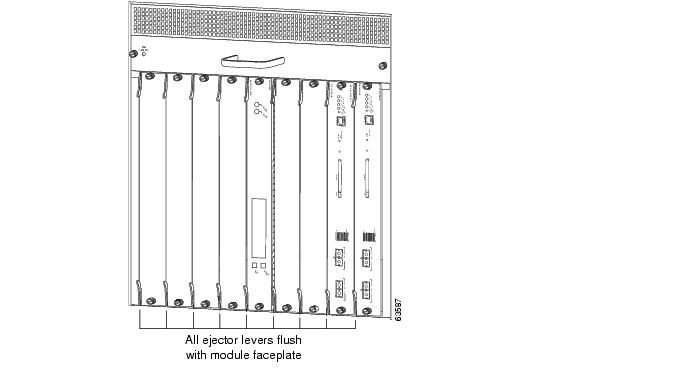
Vertical Slots
a.
Figure 11 Positioning the Module in a Vertical Slot Chassis
b.
c.
Figure 12 Clearing the EMI Gasket in a Vertical Slot Chassis
Caution
d.
Figure 13 Ejector Lever Closure in a Vertical Slot Chassis
e.
Note
Verifying the Installation
When you install the MWAM module into the Cisco 7600 chassis, the module goes through a boot sequence that requires no intervention. At the successful conclusion of the boot sequence, the green Status LED lights and remains on. If the Status LED is not green, or is a different color, see Table 7 to determine the module status.
Caution
*May 5 18:03:35.839:SP:oir_disable_notice:slot6:lcp failed to go online
Removing the MWAM
This section describes how to remove the MWAM module from the Cisco 7600 chassis.
Caution
Warning
Warning
Warning
To remove the MWAM module, perform these steps:
Step 1
a.
b.
c.
Note
Step 2
a.
b.
Step 3
Note
Step 4
Step 5
Horizontal slots
a.
b.
Vertical slots
a.
b.
Step 6
Step 7
Warning
Loading the MWAM
Cisco Supervisor Image Prerequisite
The Cisco supervisor engine must have a Cisco IOS image [Cisco IOS 12.2(14)ZA or later for Supervisor Engine 2; Cisco IOS 12.2(18)SXD1 for Supervisor Engine 720] that supports the application image on the MWAM. The latest image is available from the Cisco Software Center at:
http://www.cisco.com/cgi-bin/tablebuild.pl/ssg
For more information on the supervisor engines for the MWAM, see the following publications:
http://www.cisco.com/univercd/cc/td/doc/product/core/cis7600/iosrns/index.htm
MWAM Ordering Options
The MWAM comes from manufacturing in one of two options:
•
•
Image Loading Process
The NOAP MWAM is not operational until the user downloads an application image from the Cisco Software Center. The preloaded MWAM already has an application image; therefore, the download procedure is required only when the user wants to upgrade the application image to a later version.
The download process requires the following basic steps:
1.
2.
3.
4.
5.
Note
The image upgrade process loads the application image onto the three MWAM processor complexes.
NOAP MWAM Upgrade Procedure
The MWAM automatically attempts to boot to the application partition (AP) when it is initially installed. However, if the card is a NOAP MWAM, it fails the boot attempt because no application image is loaded. In this case, a message similar to the following appears on the console:
*May 5 18:03:35.839:SP:oir_disable_notice:slot6:lcp failed to go onlineTo set the NOAP MWAM back online, perform the following tasks.
You can now load the NOAP MWAM using the standard download/upgrade procedure.
Standard Upgrade Procedures
Table 8 lists the standard upgrade procedures available for the MWAM.
AP and MP Upgrades
The AP and MP upgrade procedures involve upgrading the AP and MP images on the compact flash of the MWAM. You upgrade one partition from the other partition. Usually, you upgrade the AP from the MP, then upgrade the MP from the AP. You upgrade the AP or MP to use new AP or MP features or fixes.
Inline Cisco IOS Image Upgrade
The inline IOS image upgrade procedure, also called the fast upgrade procedure, is similar to the AP upgrade in that both procedures upgrade the image used by the application. However, the inline Cisco IOS upgrade represents the best practice when you are upgrading multiple images on one or more MWAMs. Because this procedure is performed from the AP, you are not required to reset the module. After the upgrade, you must reload each MWAM processor to activate the images. This procedure significantly reduces the amount of down time associated with module resets.
Upgrade Notes
Read the upgrade notes before performing these procedures. (For an explanation of the MP and AP software, see the "MWAM Software Bundle" section.)
•
•
•
•
•
•
AP Upgrade Procedure
Note
To upgrade an application image to the latest available version, first locate the image in the Software Center at Cisco.com ( http://www.cisco.com/public/sw-center/).
Caution
To upgrade the application image, perform the following tasks:
The following example shows how to upgrade the AP image:
AP Upgrade Example
Sup-7606# hw-module module 4 reset cf:1Device BOOT variable for reset = <cf:1>Warning:Device list is not verified. <<<<<<<<<<<< This message is informational.Proceed with reload of module? [confirm]% reset issued for module 4Sup-7606# show module 4.. Following output displays MP image version because MWAM is reset to MP (cf:1).Mod MAC addresses Hw Fw Sw Status--- ---------------------------------- ------ ------------ ------------ -------4 0010.7b00.0c98 to 0010.7b00.0c9f 0.301 7.2(1) 2.1(0.11)m Other...Sup-7606# copy tftp://mwamimages/ap/c6svc-5mwam-g4js-bf21_10.123-5a.B pclc#4-fs:Upgrade has startedDo not reset the card till upgrade is complete!!!!!!!!!!!!!!!!!!!!!!!!!!!!!!!!!!!!!!!!!!!!!!!!!!!!!!!!!!!!!!!!!!!!!!!!!!!!!!!!!!!!!!!!!!!!!!!!!!!!!!!!!!!!!!!!!!!!!!!!!!!!!!!!!!!!!!!!!!!!!!!!!!!!!!!!!!!!!!!!!!!!!!!!!!!!!!!!!!!!!!!!!!!!!!!!!!!!!!!!!!!!!!!!!!!!!!!!!!!!!!!!!!!!!!!!!!!!!!!!!!!!!!!!!!!!!!!!!![OK - 29048727/58096640 bytes]29048727 bytes copied in 1230.204 secs (23616 bytes/sec)Sup-7606#2d21h: %SVCLC-SP-5-STRRECVD: mod 4: <Application upgrade has started>2d21h: %SVCLC-SP-5-STRRECVD: mod 4: <Do not reset the module till upgrade completes!!>Sup-7606#2d21h: %SVCLC-SP-5-STRRECVD: mod 4: <Application upgrade has succeeded>2d21h: %SVCLC-SP-5-STRRECVD: mod 4: <You can now reset the moduleSup-7606# show module 4...Mod MAC addresses Hw Fw Sw Status--- ---------------------------------- ------ ------------ ------------ -------4 0010.7b00.0c98 to 0010.7b00.0c9f 0.301 7.2(1) 2.1(0.11)m OK...Sup-7606# hw-module module 4 reset <<<<< Resets MWAM to APDevice BOOT variable for reset = <cf:4>Proceed with reload of module? [confirm]% reset issued for module 4SP:The PC in slot 4 is shutting down. Please wait ...SP:PC shutdown completed for module 4%C6KPWR-SP-4-DISABLED:power to module in slot 4 set off (Reset)%C6KPWR-SP-STDBY-4-DISABLED:power to module in slot 4 set off (Reset)%DIAG-SP-3-NO_TEST:Module 4:No test to run%OIR-SP-6-INSCARD:Card inserted in slot 4, interfaces are now onlineMP Upgrade Procedure
The MP image rarely requires upgrading. If you are instructed to update the MP, perform the following tasks:
The following example shows how to upgrade the MP image:
MP Upgrade Example
Sup-7606# copy tftp://mwamimages/mp/mp.2-1-0-11.bin.gz pclc#4-fs:Accessing tftp://mwamimages/mp/mp.2-1-0-11.bin.gz...Loading mwamimages/mp/mp.2-1-0-11.bin.gz from 10.69.1.129 (via Vlan172):!OOO!!!!!!!!!!!!!!!!!!!!!!!!!!!!!!!!!!!!!!!!!!!!!!!!!!!!!!!!!!!!!!!!!!!!!!!!!!!!!!!!!!!!!!! !!!!!!!!!!!!!!!!!!!!!!!!!!!!!!!!!!!!!!!!!!!!!!!!!!!!!!!!!!!!!!!!!!!!!!!!!!!!!!!!!!!!!!!!!! !!!!!!!!!!!!!!!!!!!!!!!!!!!!!!!!!!!!!!!!!!!!!!!!!!!!!!!!!!!!!!!!!!!!!!!!!!!!!!!!!!!!!!!!!! !!!!!!!!!!!!!!!!!!!!!!!!!!!!!!!!!!!!!!!!10300959 bytes copied in 124.360 secs (82832 bytes/sec)Sup-7606#3d19h:%SVCLC-SP-5-STRRECVD:mod 4:<Upgrade of MP was successful.>3d19h:%SVCLC-SP-5-STRRECVD:mod 4:<You can now reset the module>Sup-7606# show module 4.. Following output shows AP image name because MWAM is reset to AP (cf:4).Mod Ports Card Type Model Serial No.--- ----- -------------------------------------- ------------------ -----------4 3 MWAM Module WS-SVC-MWAM-1 SAD063703NLMod MAC addresses Hw Fw Sw Status--- ---------------------------------- ------ ------------ ------------ -------4 0010.7b00.0c98 to 0010.7b00.0c9f 0.301 7.2(1) 1.2(2.1) OkSup-7606# hw-module module 4 reset cf:1Device BOOT variable for reset = <cf:1>Warning:Device list is not verified. <<<<<<<<<<<< This message is informational.Proceed with reload of module? [confirm]% reset issued for module 4
Sup-7606# show module 4.. Following output shows MP image name because MWAM is reset to MP (cf:1).Mod MAC addresses Hw Fw Sw Status--- ---------------------------------- ------ ------------ ------------ -------4 0010.7b00.0c98 to 0010.7b00.0c9f 0.301 7.2(1) 2.1(0.11)m Other...Sup-7606# hw-module module 4 reset <<<<< Resets MWAM to AP (normal operation)Device BOOT variable for reset = <cf:4>Proceed with reload of module? [confirm]% reset issued for module 4SP:The PC in slot 4 is shutting down. Please wait ...SP:PC shutdown completed for module 4%C6KPWR-SP-4-DISABLED:power to module in slot 4 set off (Reset)%C6KPWR-SP-STDBY-4-DISABLED:power to module in slot 4 set off (Reset)%DIAG-SP-3-NO_TEST:Module 4:No test to run%OIR-SP-6-INSCARD:Card inserted in slot 4, interfaces are now online
Inline IOS Image Upgrade Procedure
This feature is introduced in Cisco IOS Release 12.3(5)B.
The AP Upgrade Procedure requires you to reset the MWAM, upgrade the image, then reset the module again. The inline Cisco IOS image upgrade, also called the fast upgrade, allows you to upgrade a Cisco IOS image without resetting the module. You must still reset each MWAM processor to load its image.
To upgrade a Cisco IOS image to the latest available version, first locate the image in the Software Center at Cisco.com:
http://www.cisco.com/cgi-bin/tablebuild.pl/ssg
Note
To upgrade the Cisco IOS image using this procedure, perform the following tasks:
The following example shows how to perform an inline Cisco IOS upgrade:
Inline IOS Upgrade Example
Sup-7606# copy tftp://mwamimages/ios/c6svc-5mwam-g4js-bi21_10.123-5.B.bin pclc#5-fs:Destination filename [svcmwam-js-mz.geo_t_040205.bin]?Accessing tftp://mwamimages/ios/svcmwam-js-mz.geo_t_040205.bin...Loading mwamimages/ios/svcmwam-js-mz.geo_t_040205.bin from 10.102.16.25 (via Vlan1): !OOO!!!!!!!!!!!!!!!!!!!!!!!!!!!!!!!!!!!!!!!!!!!!!!!!!!!!!!!!!!!!!!!!!!!!!!!!!!!!!!!!!!!!!!!!!!!!!!!!!!!!!!!!!!!!!!!!!!!!!!!!!!!!!!!!!!!!!!!!!!!!!!!!!!!!!!!!!!!!!!!!!!!!!!!!!!!!!!!!!!!!!!!!!!!!!!!!!!!!!!!!!!!!!!!!!!!!!!!!!!!!!!!!!!!!!!!!!!!!!!!!!!!!!!!!!!!!!!!!!!!!!!!!!!!!!!!!!!!!!!!!!!!!!!!!!!!!!!!!!!!!!!!!!!!!!!!!!!!!!!!!!!!!!!!!!!!!!!!!!!!!!!!!!!!!!!!!!!!!!!!!!!!!!!!!!!!!!!!!!!!!!!!!!!!!!!!!!!!!!!!!!!!!!!!!!!!!!!!!!!!!!!!!!!!!!!!!!!!!!!!!!!!!!!
!!!!!!!!!!!!!!!!!!!!!!!!!!!!!!!!!!!!!!!!!!!!!!!!!!!!!!!!!!!!!!!!!!!!!!!!!!!!!!!!!!!!!!!!!!
!!!!!!!!!!!!!!!!!!!!!!!!!!!!!!!!!!!!!!!!!!!!!!!!!!!!!!!!!!!!!!!!!!!!!!!!!!!!!!!!!!!!!!!!!!
!!!!!!!!!!!!!!!!!!!!!!!!!!!!!!!!!!!!!!!!!!!!!!!!!!!!!!!!!!!!!!!!!!!!!!!!!!!!!!!!!!!!!!!!!!
[OK - 11549631 bytes]11549631 bytes copied in 107.552 secs (107386 bytes/sec)Sup-7606#2w1d: %SVCLC-SP-5-STRRECVD: mod 5: <Application upgrade has started>2w1d: %SVCLC-SP-5-STRRECVD: mod 5: <Do not reset the module till upgrade completes!!>2w1d: %SVCLC-SP-5-STRRECVD: mod 5: <Configuring svcmwam-js-mz.geo_t_040205>2w1d: %SVCLC-SP-5-STRRECVD: mod 5: <Application upgrade has succeeded>2w1d: %SVCLC-SP-5-STRRECVD: mod 5: <You can now reset the module>Sup-7606#Sup-7606# show module 5..Mod MAC addresses Hw Fw Sw Status--- ---------------------------------- ------ ------------ ------------ -------4 0010.7b00.0c98 to 0010.7b00.0c9f 0.301 7.2(1) 2.1(0.11)m Other...Sup-7606# session slot 5 processor 1The default escape character is Ctrl-^, then x.You can also type 'exit' at the remote prompt to end the sessionTrying 127.0.0.91 ... OpenSVCMWAM Image version 2.1(0.1b)Tue Oct 14 11:04:43 EDT 2003Copyright (c) 2002-2003 by cisco Systems, Inc.All rights reserved.Kernel 2.4.10.komodo on an i686login: rootPassword:SVCMWAM Image version 2.1(0.1b)Tue Oct 14 11:04:43 EDT 2003Copyright (c) 2002-2003 by cisco Systems, Inc.All rights reserved.SVCMWAM Image version 2.1(0.1b)Tue Oct 14 11:04:43 EDT 2003Copyright (c) 2002-2003 by cisco Systems, Inc.All rights reserved.root@mwam-5# reload allroot@mwam-5# show imagesDevice name Partition# Image name----------- ---------- ----------Compact flash(cf) 6 SIMPSON_RAM.binVersion Information:Compiled Tue 19-Aug-03 13:35 by dchihCompact flash(cf) 6svcmwam-g4js-mz.123-7.3.TVersion Information:
Compiled Wed 11-Feb-04 21:26 by eaarmas$AP software is c6svc-5mwam-g4js-bi21_10.123-5.Broot@mwam-5# show versionSVCMWAM Image version 2.1(0.3b)Thu Feb 19 05:30:06 EST 2004Copyright (c) 2002-2003, 2004 by cisco Systems, Inc.All rights reserved.AP software is c6svc-5mwam-g4js-bi21_10.123-5.BAP software is based upon Maintenance image version:3.1(0.2)IOS Software is svcmwam-g4js-mz.123-7.3.T6 Processor ConfigurationLine Card Number :WS-SVC-MWAM-1Number of Pentium-class Processors : 1BIOS Vendor:Phoenix Technologies Ltd.BIOS Version:4.0-Rel 6.0.4Total available memory:500 MBSize of compact flash:122 MBroot@mwam-5#
Reverting to Previous IOS Image
If you decide to revert to the previous Cisco IOS image, establish a session to the PC, log in as root, and run the following command:
root@mwam-5# restore iosRestoring imageRestoring configuration filesOperation completed successfullyroot@mwam-5#This action restores the previous Cisco IOS image. You must then reload the MWAM processor(s) to activate the image.
Note
Upgrading the ROMMON Image
You should only upgrade the ROMMON image when instructed to do so. It is not necessary to upgrade the ROMMON image each time you download the application image.
However, because the ROMMON images is bundled with the application image, you must download the application image to properly upgrade the ROMMON image.
To upgrade the ROMMON image, perform the following tasks after downloading an application image:
Step 1
Router# enableEnters privileged EXEC mode.
Step 2
Router# session slot slot_number processor
processor_number (2-6)
Establishes a session to an MWAM processor.
Note
Step 3
Router# upgrade rom-monitorGets the ROMMON image (from the compact flash card) for the processor complex.
Step 4
Repeat above steps for each processor complex.
Loads the ROMMON image on all complexes.
Step 5
Router# hw-module module slot_number reset
cf:4
Resets the MWAM to upgrade the ROMMON images on the module.
Sup-7600# enableSup-7600# session slot 4 processor 2The default escape character is Ctrl-^, then x.You can also type 'exit' at the remote prompt to end the sessionTrying 127.0.0.62 ... OpenSup-7600#Press RETURN to get started!Sup-7600#upgrade rom-monitorMWAM: ROMMON image upgrade in progress.Loading SIMPSON_RAM.bin from 128.0.1.1 (via GigabitEthernet0/1): !!!!!!!!!!!!!!!!!!!!!!!!!!!!!!!!!!!!!![OK - 190592/380928 bytes]MWAM: Erasing FUR Region.MWAM: Programming Flash.MWAM: Verifying new ROMMON image.MWAM: ROMMON image upgrade complete.MWAM: The card must be reset for this to take effect.Sup-7600# hw-module module 4 reset cf:4Device BOOT variable for reset = <cf:4>Proceed with reload of module? [confirm]% reset issued for module 4SP:The PC in slot 4 is shutting down. Please wait ...SP:PC shutdown completed for module 4%C6KPWR-SP-4-DISABLED:power to module in slot 4 set off (Reset)%C6KPWR-SP-STDBY-4-DISABLED:power to module in slot 4 set off (Reset)%DIAG-SP-3-NO_TEST:Module 4:No test to run%OIR-SP-6-INSCARD:Card inserted in slot 4, interfaces are now onlineBooting the Application Image
The Application Partition (AP) is specific to each MWAM and stores a Cisco IOS application image for the processors on the MWAM. By default, the MWAM boots to the application image when initially powered on.
To boot the application image, use the following command:
Step 1
Sup-7606> enableEnters privileged EXEC mode.
Step 2
Sup-7606# hw-module module slot_number
reset
Reboots the MWAM.
For example, if you have an MWAM installed in slot 4, enter the following commands:
Sup-7606# enableSup-7606# hw-module module 4 resetDevice BOOT variable for reset = <cf:4>Proceed with reload of module? [confirm]% reset issued for module 4SP:The PC in slot 4 is shutting down. Please wait ...SP:PC shutdown completed for module 4%C6KPWR-SP-4-DISABLED:power to module in slot 4 set off (Reset)%C6KPWR-SP-STDBY-4-DISABLED:power to module in slot 4 set off (Reset)%DIAG-SP-3-NO_TEST:Module 4:No test to run%OIR-SP-6-INSCARD:Card inserted in slot 4, interfaces are now onlineMWAM Module Configuration
This section provides an overview of MWAM configuration.
Using the CLI
MWAM configuration requires user interaction with two Cisco command line interfaces:
•
–
–
–
•
–
–
–
On the Cisco Catalyst 6500 series Supervisor Engine 2, the main commands are:
•
•
On the session CLI to the MWAM processor, you can access Cisco IOS commands to configure the application as required. This includes configuring the VLAN subinterfaces to connect to the switch fabric.
Note
Unsupported Commands
The MWAM does not support the following commands:
•
•
•
Note
MWAM Processor Naming Conventions
To establish a session, you must know the processor number with which you want to establish a session. As part of the mwam module command, you must also know the mapping between the processors on the MWAM and the Ethernet port/VLAN that connects the processor to the switch fabric. See the individual commands in the "Command Reference" section for more information.
Table 9 lists important information about the processors on the MWAM. The information in this matrix corresponds to the MWAM architecture shown in Figure 1.
Table 9 MWAM Processor Matrix
1
Control
—
2
1
1 Gigabyte
Gi 0/0
Slot x, port 2
3
4
2
1 Gigabyte
Gi 0/0
Slot x, port 3
5
6
0
512 Mbyte
Gi 0/0
Slot x, port 1
71
1 Processor 7 is disabled for use by some applications because processors 6 and 7 would be sharing the smaller memory size on processor complex 0.
Configuration Tasks
The following configuration tasks are listed sequentially:
•
•
•
•
•
•
•
•
•
•
•
Assigning VLANs to the MWAM
Note
Assigning VLANs to the MWAM requires you to understand the mapping between the processors on the MWAM and the Ethernet port/VLAN that connects the processor to the switch fabric. See Table 1 and Figure 1 for this information.
To assign VLANs to the MWAM, enter this command for each of the three switch fabric interface ports (ports 1, 2, and 3) that connect the supervisor engine to the MWAM:
This example assigns VLANs 1 through 1005 to ports 1 through 3 that connect to the MWAM in slot 5:
Sup-7606>Sup-7606> enableSup-7606# configure terminalEnter configuration commands, one per line. End with CNTL/Z.Sup-7606(config)# mwam module 5 port 1 allowed-vlan 1-1005Sup-7606(config)# mwam module 5 port 2 allowed-vlan 1-1005Sup-7606(config)# mwam module 5 port 3 allowed-vlan 1-1005You may need to wait up to 30 seconds for spanning tree to converge for connectivity.
Configuring MWAM VLANs on the Cisco Supervisor Engine
The user must configure VLANs on the supervisor engine to forward traffic to the switch fabric. On the session CLI to the MWAM processor, the user has access to Cisco IOS commands to configure the VLANs. Two configuration modes are available for configuring supervisor engine VLANs:
•
•
Caution
VLAN Database Mode
Note
To configure VLANs on the supervisor engine in the VLAN database mode, perform this task:
This example shows how to configure VLANs on the supervisor engine in the VLAN database mode:
Sup-7600# enableSup-7600# vlan databaseSup-7600(vlan)# vlan 100VLAN 100 added:Name: VLAN100Sup-7600(vlan)# exitAPPLY completed.Exiting....Global Configuration Mode
Note
To configure VLANs on the supervisor engine in the global configuration mode, perform this task:
This example shows how to configure VLANs on the supervisor engine in global configuration mode:
Sup-7600# configure terminalSup-7600(vlan)# vlan 100-200Sup-7600(config-vlan)# endConfiguring Layer 3 Interfaces on VLANs
The user can configure Layer 3 interfaces on the MWAM VLANs if required by the application.
Note
To configure the Layer 3 VLAN interface, perform this task:
This example shows how to configure the Layer 3 VLAN interface:
Sup-7600# configure terminalSup-7600(config)# interface vlan 100Sup-7600(config-if)# ip address 10.10.1.10 255.255.255.0Sup-7600(config-if)# no shutdownSup-7600(config-if)# exitEstablishing Processor Session to Configure Application
To configure the application on an MWAM processor, establish a session to each MWAM processor using the following command in Privileged EXEC mode:
This example shows how to establish a session to an MWAM processor:
Sup-7606> enableSup-7606# session slot 6 processor 4The default escape character is Ctrl-^, then x.You can also type 'exit' at the remote prompt to end the sessionTrying 127.0.0.64 ... Open <<<<< last part of address indicates slot 6, processor 4mwam-6-4#Press RETURN to get started!mwam-6-4# dir bootflash:Directory of bootflash:/No files in directory524288 bytes total (0 bytes free) <<<response indicates that boot flash requires formattingmwam-6-4# format bootflash:Format operation may take a while. Continue? [confirm]Format operation will destroy all data in "bootflash:". Continue? [confirm]Format of bootflash completeAfter configuring the application, make a backup of the configuration as follows:
mwam-6-4# copy running-config startup-configDestination filename [startup-config]?...IOS Command Restrictions at the Processor Level
When you establish a session to an MWAM processor, you can access Cisco IOS commands to configure the application as required. This section describes limitations, restrictions, and operating notes when issuing Cisco IOS commands at the MWAM processor level. The following topics are covered:
•
•
•
•
Reload Command
Caution
Also, if you issue the reload command at the supervisor level, the reload occurs for the entire chassis, which includes all modules in the chassis. If the chassis contains five MWAMs, and each MWAM contains five active processors, then 25 routers are reloaded by this operation.
Copy Running Configuration Command
Local Mode Operation
For MWAMs operating in local mode, the copy running-config command copies the running configuration to NVRAM on the MWAM. See the example that follows:
mwam-6-4# copy running-config startup-configDestination filename [startup-config]?Building configuration...[OK]mwam-6-4# show startupUsing 505 out of 524280 bytes!!NVRAM config last updated at <time stamp><configuration>endSupervisor Mode Operation
For MWAMs operating in supervisor mode, the copy running-config command copies the running configuration to the supervisor module(s). See the example that follows:
mwam-6-4# copy running-config startup-configDestination filename [startup-config]?Writing bootflash:SLOT6PC4.cfgConfig uploaded to supervisor in slot 1Writing bootflash:SLOT6PC4.cfgConfig uploaded to supervisor in slot 2Config uploaded to 2 supervisor(s)
Note
Copy TFTP Command
Caution
Erase Startup Configuration Command
Local Mode
When operating in local mode, use the command erase startup-config (issued at the MWAM processor level) to erase the local NVRAM configuration file.
Supervisor Mode
When operating in supervisor mode, erase the configuration file in the supervisor boot flash with the following commands from the supervisor console:
•
•
Show Startup Configuration Command
Local Mode
When operating in local mode, the command show startup-config (issued at the MWAM processor level) shows the contents of the NVRAM configuration file.
Supervisor Mode
When operating in supervisor mode, show the startup configuration using the following commands from the supervisor console:
•
•
Note
Squeeze Bootflash Command
When operating in supervisor mode, the operator must maintain adequate file space on the supervisor boot flash. This includes periodically using the squeeze bootflash command to consolidate available space.
High Speed Router Protocol Configuration
The MWAM architecture imposes some limitations on the configuration of the High Speed Router Protocol (HSRP). You must not configure HSRP groups for processors that are in the same processor complex. Because of the MWAM architecture, when one processors fails (i.e., crashes), both processors in the complex reload. For this reason, HSRP groups are not supported for processors in the same complex.
You can configure HSRP groups for processors on the same MWAM as long as they are not in the same complex. A preferable strategy is to configure HSRP groups to span processors on different MWAMs.
Multicast MAC Addressing
The Cisco IOS supports multicast Media Access Control (MAC) addressing in multiple ways. The MWAM supports some of these ways better than others. For applications such as HSRP where a single multicast MAC address is used, the MWAM can support the address in the same way as any other MAC address.
Each processor complex supports up to eight explicit MAC address entries. However, when exceeding this limit, the MWAM must use the multicast promiscuous mode. In this mode, all multicast addresses are received by the processor and must be validated in software rather than hardware. This restriction places additional load on the processor. Other types of multicast MAC addressing in the IOS (e.g., IP multicast routing) require multicast promiscuous mode at all times.
When multicast promiscuous mode is enabled on both processors in a complex, each one processes all multicast packets. This condition leads to additional processing at the MAC layer. For this reason, Cisco recommends that IP multicast routing be configured on only one processor per complex.
You can determine the mode with the show controller command.
Configuring a LAN Port for Layer 2 Switching
To configure physical interfaces that connect to the servers or the clients in the corresponding VLAN, perform these steps:
Step 1
Router# configure terminalEnters Configuration mode.
Step 2
Router(config)# interface type1 slot/portSelects the LAN port to configure.
Step 3
Router(config-if)# switchportConfigures the LAN port for Layer 2 switching.
Note
Step 4
Router(config-if)# switchport mode accessPuts the LAN port into permanent nontrunking mode and negotiates to convert the link into a nontrunk link. The LAN port becomes a nontrunk port even if the neighboring LAN port does not agree to the change.
Step 5
Router(config-if)# switchport access vlan
vlan_ID
Configures the default VLAN, which is used if the interface stops trunking.
Step 6
Router(config-if)# no shutdownActivates the interface.
1 type = ethernet, fastethernet, gigabitethernet, or tengigabitethernet
This example shows how to configure a physical interface as a Layer 2 interface and assign it to a VLAN:
pro-6-2# configure terminalEnter configuration commands, one per line. End with CNTL/Z.pro-6-2(config)# interface gigabitethernet 1/1pro-6-2(config-if)# switchportpro-6-2(config-if)# switchport mode accesspro-6-2(config-if)# switchport access vlan 100pro-6-2(config-if)# no shutdownpro-6-2(config-if)# exitConfiguring Subinterfaces on an MWAM Processor
The IEEE 802.1Q protocol is used to provide trunks between switches. The switches use the trunks to share VLANs and transfer data between VLANs on different switches. Create as many subinterfaces as needed to connect to different networks. You configure 802.1q encapsulation on each subinterface to the VLANs created on the supervisor engine.
To enable 802.1q encapsulation on each of the processors on the MWAM, use the following commands in interface configuration mode:
Router# configure terminalEnters configuration mode.
Router(config)# interface type1 slot/portSpecifies the subinterface on which IEEE 802.1Q is used.
Router(config-if)# encapsulation dot1Q
vlan_id
Defines the encapsulation format as IEEE 802.1Q (dot1q), and specifies the VLAN identifier.
Router(config-if)# ip address ip-address
mask
Sets a primary IP address for an interface.
1 type = ethernet, fastethernet, gigabitethernet, or tengigabitethernet
This example shows how to enable IEEE 802.1Q on VLANs 310 and 401.
pro-6-2# configure terminalEnter configuration commands, one per line. End with CNTL/Z.pro-6-2(config)# interface GigabitEthernet0/0pro-6-2(config-if)# no ip address!pro-6-2(config-if)# interface GigabitEthernet0/0.310pro-6-2(config-if)# encapsulation dot1Q 310pro-6-2(config-if)# ip address 10.1.1.44 255.255.255.0!pro-6-2(config-if)# interface GigabitEthernet0/0.401pro-6-2(config-if)# encapsulation dot1Q 401pro-6-2(config-if)# ip address 10.121.68.44 255.255.255.0Verifying the MWAM Configuration
To verify the configuration, enter these commands:
Note
This example shows how to verify that the module is in forwarding (FWD) state:
Sup-7600# show spanning-tree vlan 100VLAN0100Spanning tree enabled protocol ieeeRoot ID Priority 32768Address 0009.e9b2.b864This bridge is the rootHello Time 2 sec Max Age 20 sec Forward Delay 15 secBridge ID Priority 32768Address 0009.e9b2.b864Hello Time 2 sec Max Age 20 sec Forward Delay 15 secAging Time 15Interface Role Sts Cost Prio.Nbr Type---------------- ---- --- --------- -------- --------------------------------Gi3/1 Desg FWD 4 128.129 P2pGi4/1 Desg FWD 4 128.193 P2pPo261 Desg FWD 3 128.833 P2pRouterThis example shows how to verify that the VLAN information displayed matches the VLAN configuration:
Sup-7600# show mwam module 3 port 1 stateMwam module 3 data-port 1:Switchport: EnabledAdministrative Mode: trunkOperational Mode: trunkAdministrative Trunking Encapsulation: dot1qOperational Trunking Encapsulation: dot1qNegotiation of Trunking: OffAccess Mode VLAN: 1 (default)Trunking Native Mode VLAN: 1 (default)Trunking VLANs Enabled: 1-1000Pruning VLANs Enabled: 2-1001Vlans allowed on trunk:1-1000Vlans allowed and active in management domain:1-2,95,100Vlans in spanning tree forwarding state and not pruned:1-2,95,100Allowed-vlan : 1-1000Sup-7600# show mwam module 3 port 1 trafficSpecified interface is up line protocol is upHardware is C6k 1000Mb 802.3, address is 00e0.b0ff.3a18 (via 00e0.b0ff.3a18)MTU 1500 bytes, BW 1000000 Kbit, DLY 10 usec,reliability 255/255, txload 1/255, rxload 1/255Encapsulation ARPA, loopback not setKeepalive set (10 sec)Full-duplex, 1000Mb/sLast input never, output never, output hang neverLast clearing of "show interface" counters neverInput queue: 0/2000/0/0 (size/max/drops/flushes); Total output drops: 77Queueing strategy: fifoOutput queue :0/40 (size/max)5 minute input rate 0 bits/sec, 0 packets/sec5 minute output rate 1000 bits/sec, 1 packets/sec24598 packets input, 2138920 bytes, 0 no bufferReceived 0 broadcasts, 0 runts, 0 giants, 0 throttles0 input errors, 0 CRC, 0 frame, 0 overrun, 0 ignored0 input packets with dribble condition detected928697 packets output, 68993318 bytes, 0 underruns0 output errors, 0 collisions, 34 interface resets0 babbles, 0 late collision, 0 deferred0 lost carrier, 0 no carrier0 output buffer failures, 0 output buffers swapped outConverting to Supervisor Mode
Note
Tip
To convert an MWAM processor from local mode to supervisor mode, complete the following steps.
This example shows how to convert processor 4 on the MWAM in slot 6 to the supervisor mode:
Sup-7606> enableSup-7606# session slot 6 processor 4mwam-6-4> enablemwam-6-4# show mwam config-modemwam config-mode localmwam-6-4# mwam config-mode supervisorWriting bootflash:SLOT6PC4.cfgConfig uploaded to supervisor in slot 1Writing bootflash:SLOT6PC4.cfgConfig uploaded to supervisor in slot 2Successfully changed mode: mwam config-mode supervisor
Note
Caution
Configuring Remote Console and Logging
Note
To configure the remote console and logging feature, complete the following steps:
Step 1
Sup-7606# configure terminalEnters configuration mode on the supervisor console.
Step 2
Sup-7606(config)# logging
listen mwam udp_port
Configures the UDP port for MWAM logging input to the supervisor engine.
Step 3
Sup-7606(config)# mwam module
{slot_number | all} cpu
{processor_number | all}
logging log_level
(Optional) Configures the severity level of MWAM logging information to send to the supervisor engine.
Step 4
Sup-7606(config)# exitExits configuration mode.
Step 5
Sup-7606# session slot
slot_number processor
processor_number
Establishes a Telnet session to the MWAM processor.
Step 6
mwam-6-4# configure terminalEnters configuration mode on the MWAM processor console.
Step 7
mwam-6-4(config)# logging
main-cpu udp_port [log_level]
[ip_address]
Configures MWAM log redirection to the supervisor engine.
Note
When the Remote Console and Logging feature is configured, you can use the execute-on command to initiate a remote command request to an MWAM processor. See the Command Reference section of this document for details.
Clearing MWAM Session from Supervisor Console
To clear an MWAM session from the supervisor console, complete the following steps:
This example shows how to clear an MWAM session on processor 2 of the MWAM in slot 7.
Sup-7606# show tcp briefTCB Local Address Foreign Address (state)4345AC80 9.3.67.21.23 10.76.82.75.33713 ESTAB509F0CD0 9.3.67.21.23 10.76.82.75.33777 ESTAB43456D80 9.3.67.21.23 10.76.82.75.33712 ESTAB43455A10 127.0.0.12.30211 127.0.0.72.23 ESTAB <<<< Connection to clear4343BD18 9.3.67.21.23 9.3.66.4.11000 ESTAB43449A0C 127.0.0.12.24068 127.0.0.71.23 ESTABSup-7606# clear tcp tcb 43455A10Sup-7606#Recovering from MWAM Processor Lockout
Occasionally, you may discover that you are unable to log into an MWAM processor. Configuration mistakes can cause this lockout condition to occur.
To recover from the MWAM processor lockout condition, complete the following steps:
Step 1
Sup-7606# session slot
slot_number processor 1
Establishes a Telnet session to MWAM processor 1.
Note
Step 2
root@mwam-5# recover-ios
complex_number
Sets the configuration register to boot with a clean configuration.
Note
Step 3
root@mwam-5# reload complex
complex_number
Reloads the processor complex.
Note
Step 4
root@mwam-5# normal-iosSets the configuration register to boot with a normal configuration to ensure that processors do not ignore their startup configurations.
The following example shows how to recover from the lockout condition on processor complex 0 of the MWAM in slot 5:
Sup-7600# session slot 5 processor 1The default escape character is Ctrl-^, then x.You can also type 'exit' at the remote prompt to end the sessionTrying 127.0.0.51 ... OpenSVCMWAM Image version 1.2(2.1-Eng)Fri Oct 3 05:32:39 EDT 2003Copyright (c) 2002-2003 by cisco Systems, Inc.All rights reserved.Kernel 2.4.10.komodo on an i686login: rootPassword:SVCMWAM Image version 1.2(2.1-Eng)Fri Oct 3 05:32:39 EDT 2003Copyright (c) 2002-2003 by cisco Systems, Inc.All rights reserved.root@mwam-5# recover-ios 0processing -pprocessing -cSetting DHCP options for processor complex 0Setting config-reg value to: 0x40Base external MAC: "0005.9A3B.A180"Internet Software Consortium DHCP Server V3.0.1rc6Copyright 1995-2001 Internet Software Consortium.All rights reserved.For info, please visit http://www.isc.org/products/DHCPWrote 0 deleted host decls to leases file.Wrote 0 new dynamic host decls to leases file.Wrote 0 leases to leases file.Listening on LPF/eth0/02:00:00:00:0f:00/128.0.1.0/24Sending on LPF/eth0/02:00:00:00:0f:00/128.0.1.0/24Listening on LPF/eth1/02:00:00:00:0f:10/128.0.2.0/24Sending on LPF/eth1/02:00:00:00:0f:10/128.0.2.0/24Sending on Socket/fallback/fallback-netroot@mwam-5# reload complex 0root@mwam-5# normal-iosBase external MAC: "0005.9A3B.A180"Internet Software Consortium DHCP Server V3.0.1rc6Copyright 1995-2001 Internet Software Consortium.All rights reserved.For info, please visit http://www.isc.org/products/DHCPWrote 0 deleted host decls to leases file.Wrote 0 new dynamic host decls to leases file.Wrote 0 leases to leases file.Listening on LPF/eth0/02:00:00:00:0f:00/128.0.1.0/24Sending on LPF/eth0/02:00:00:00:0f:00/128.0.1.0/24Listening on LPF/eth1/02:00:00:00:0f:10/128.0.2.0/24Sending on LPF/eth1/02:00:00:00:0f:10/128.0.2.0/24Sending on Socket/fallback/fallback-netCommand Reference
This section lists new and revised commands specific to the MWAM configuration. All other commands used with this feature are documented in Cisco IOS Release 12.3 command reference publications. The commands are categorized according to the console from which they are executed.
Supervisor Console Commands
The following commands are available at the supervisor console:
Processor Control (PC) Commands
The PC commands are available when you session into MWAM processor 1 from the supervisor console. The PC commands provide specialized control functions for MWAM processors. You must use the session slot command to establish a connection to processor 1. Then log into the PC as root user with the password cisco.
•
MWAM Console Commands
The following commands are available at the MWAM console:
mwam module allowed-vlan
To configure Ethernet connectivity from the backplane (switch fabric) to the individual processors on the MWAM, use the mwam module allowed-vlan command. To remove this configuration, use the no form of the command.
mwam module slot_number port number allowed-vlan vlan-list
no mwam module slot_number port number allowed-vlan vlan-list
Syntax Description
slot_number
Specifies the slot that the module is plugged into.
port number
Specifies the port number (1-3) used to connect to a processor complex within the MWAM (see Figure 1).
allowed-vlan vlan-list
Configures the appropriate VLANs for this port.
Default
There are no default behaviors or values.
Command Mode
Global configuration
Command History
Usage Guidelines
Each processor is connected to the backplane (switch fabric) through an Ethernet port connection. When both processors within a complex are enabled, they are required to share the Ethernet port connection, thus their port configuration must be common.
Example
The following example illustrates the mwam module allowed-vlan command:
router(config)# mwam module 4 port 2 allowed-vlan 101mwam module vlan-based
To assign MWAM traffic to a VLAN QoS policy, use the mwam module vlan-based command in global configuration mode. To remove this configuration, use the no form of the command.
mwam module slot_number port port_number vlan-based
no mwam module slot_number port port_number vlan-based
Syntax Description
Default
There are no default behaviors or values.
Command Mode
Global configuration
Command History
Usage Guidelines
Use this command to assign MWAM traffic to a VLAN QoS policy.
See Figure 1 and Table 1 to determine which port corresponds to each processor.
Example
The following example illustrates the mwam module vlan-based command:
Sup-7606(config)# mwam module 5 port 1 vlan-basedSup-7606(config)# mwam module 5 port 2 vlan-basedSup-7606(config)# mwam module 5 port 3 vlan-basedsession slot
To establish a command session to a processor on an MWAM, use the session slot command in privileged EXEC mode.
session slot slot_number processor processor_number
Syntax Description
Default
There are no default behaviors or values.
Command Mode
Privileged EXEC mode
Command History
Usage Guideline
When you session into processor 1, you must enter the user name (root) and password (cisco).
Examples
The following example illustrates the session slot command for processor 2 on the MWAM in slot 9:
Sup-7606# session slot 9 processor 2The default escape character is Ctrl-^, then x.You can also type 'exit' at the remote prompt to end the sessionTrying 127.0.0.92 ... Openproc2-9>Press RETURN to get started!proc2-9>The following example illustrates the session slot command for processor 1 on the MWAM in slot 9:
Sup-7606# session slot 9 processor 1The default escape character is Ctrl-^, then x.You can also type 'exit' at the remote prompt to end the sessionTrying 127.0.0.91 ... OpenSVCMWAM Image version 2.1(0.1b)Tue Oct 14 11:04:43 EDT 2003Copyright (c) 2002-2003 by cisco Systems, Inc.All rights reserved.Kernel 2.4.10.komodo on an i686login: rootPassword:SVCMWAM Image version 2.1(0.1b)Tue Oct 14 11:04:43 EDT 2003Copyright (c) 2002-2003 by cisco Systems, Inc.All rights reserved.SVCMWAM Image version 2.1(0.1b)Tue Oct 14 11:04:43 EDT 2003Copyright (c) 2002-2003 by cisco Systems, Inc.All rights reserved.root@mwam-9#show mwam module
To display connectivity information about individual processors on the MWAM, use the show mwam module command in Privileged EXEC mode.
show mwam module slot_number port port_number {state | traffic}
Syntax Description
slot_number
Displays the slot that the module is plugged into.
port port_number
Displays the port number (1-3) used to connect to a processor complex within an MWAM (see Figure 1).
state
Displays the interface status.
traffic
Displays the interface statistics.
Default
There are no default behaviors or values.
Command Mode
Privileged EXEC mode
Command History
Example
The following example illustrates the show mwam module command:
router# show mwam module 7 ?port Data Portrouter# show mwam module 7 port 1 ?state Show interface status.traffic Show interface statistics.router# show mwam module 7 port 1 ?state Show interface status.traffic Show interface statistics.router# show mwam module 7 port 1 stateMwam module 7 data-port 1:Switchport: EnabledAdministrative Mode: trunkOperational Mode: trunkAdministrative Trunking Encapsulation: dot1qOperational Trunking Encapsulation: dot1qNegotiation of Trunking: OffAccess Mode VLAN: 1 (default)Trunking Native Mode VLAN: 1 (default)Trunking VLANs Enabled: 1-999Pruning VLANs Enabled: 2-1001Vlans allowed on trunk:1-999Vlans allowed and active in management domain:1,3,11-12,17,60Vlans in spanning tree forwarding state and not pruned:1,3,11-12,17,60Allowed-vlan : 1-999router# show mwam module 7 port 1 trafficSpecified interface is up line protocol is upHardware is C6k 1000Mb 802.3, address is 0010.7b00.0cb0 (via 0010.7b00.0cb0)MTU 1500 bytes, BW 1000000 Kbit, DLY 10 usec,reliability 255/255, txload 1/255, rxload 1/255Encapsulation ARPA, loopback not setKeepalive set (10 sec)Full-duplex, 1000Mb/sLast input never, output never, output hang neverLast clearing of "show interface" counters neverInput queue: 0/2000/0/0 (size/max/drops/flushes); Total output drops: 67Queueing strategy: fifoOutput queue :0/40 (size/max)5 minute input rate 0 bits/sec, 0 packets/sec5 minute output rate 1000 bits/sec, 3 packets/sec0 packets input, 0 bytes, 0 no bufferReceived 0 broadcasts, 0 runts, 0 giants, 0 throttles0 input errors, 0 CRC, 0 frame, 0 overrun, 0 ignored0 input packets with dribble condition detected46504312 packets output, 2501255885 bytes, 0 underruns0 output errors, 0 collisions, 10 interface resets0 babbles, 0 late collision, 0 deferred0 lost carrier, 0 no carrier0 output buffer failures, 0 output buffers swapped outrouter# show mwam module 7 port 2 stateMwam module 7 data-port 2:Switchport: EnabledAdministrative Mode: trunkOperational Mode: trunkAdministrative Trunking Encapsulation: dot1qOperational Trunking Encapsulation: dot1qNegotiation of Trunking: OffAccess Mode VLAN: 1 (default)Trunking Native Mode VLAN: 1 (default)Trunking VLANs Enabled: 1-999Pruning VLANs Enabled: 2-1001Vlans allowed on trunk:1-999Vlans allowed and active in management domain:1,3,11-12,17,60Vlans in spanning tree forwarding state and not pruned:1,3,11-12,17,60Allowed-vlan : 1-999router# show mwam module 7 port 2 trafficSpecified interface is up line protocol is upHardware is C6k 1000Mb 802.3, address is 0010.7b00.0cb1 (via 0010.7b00.0cb1)MTU 1500 bytes, BW 1000000 Kbit, DLY 10 usec,reliability 255/255, txload 1/255, rxload 1/255Encapsulation ARPA, loopback not setKeepalive set (10 sec)Full-duplex, 1000Mb/sLast input 00:00:09, output never, output hang neverLast clearing of "show interface" counters neverInput queue: 0/2000/0/0 (size/max/drops/flushes); Total output drops: 68Queueing strategy: fifoOutput queue :0/40 (size/max)5 minute input rate 1000 bits/sec, 1 packets/sec5 minute output rate 1000 bits/sec, 2 packets/sec24922473 packets input, 430882532 bytes, 0 no bufferReceived 93145 broadcasts, 0 runts, 0 giants, 0 throttles0 input errors, 0 CRC, 0 frame, 0 overrun, 0 ignored0 input packets with dribble condition detected26261319 packets output, 4263983434 bytes, 0 underruns0 output errors, 0 collisions, 10 interface resets0 babbles, 0 late collision, 0 deferred0 lost carrier, 0 no carrier0 output buffer failures, 0 output buffers swapped outrouter# show mwam module 7 port 3 stateMwam module 7 data-port 3:Switchport: EnabledAdministrative Mode: trunkOperational Mode: trunkAdministrative Trunking Encapsulation: dot1qOperational Trunking Encapsulation: dot1qNegotiation of Trunking: OffAccess Mode VLAN: 1 (default)Trunking Native Mode VLAN: 1 (default)Trunking VLANs Enabled: 1-999Pruning VLANs Enabled: 2-1001Vlans allowed on trunk:1-999Vlans allowed and active in management domain:1,3,11-12,17,60Vlans in spanning tree forwarding state and not pruned:1,3,11-12,17,60Allowed-vlan : 1-999router# show mwam module 7 port 3 trafficSpecified interface is up line protocol is upHardware is C6k 1000Mb 802.3, address is 0010.7b00.0cb2 (via 0010.7b00.0cb2)MTU 1500 bytes, BW 1000000 Kbit, DLY 10 usec,reliability 255/255, txload 1/255, rxload 1/255Encapsulation ARPA, loopback not setKeepalive set (10 sec)Full-duplex, 1000Mb/sLast input 00:00:11, output never, output hang neverLast clearing of "show interface" counters neverInput queue: 0/2000/0/0 (size/max/drops/flushes); Total output drops: 22Queueing strategy: fifoOutput queue :0/40 (size/max)5 minute input rate 0 bits/sec, 0 packets/sec5 minute output rate 1000 bits/sec, 2 packets/sec35270 packets input, 5189978 bytes, 0 no bufferReceived 4444 broadcasts, 0 runts, 0 giants, 0 throttles0 input errors, 0 CRC, 0 frame, 0 overrun, 0 ignored0 input packets with dribble condition detected46510270 packets output, 2501832096 bytes, 0 underruns0 output errors, 0 collisions, 10 interface resets0 babbles, 0 late collision, 0 deferred0 lost carrier, 0 no carrier0 output buffer failures, 0 output buffers swapped out
Note
mwam bootflash access
Note
To enable file transfer requests between the supervisor boot flash and the individual processors on the MWAM, use the mwam bootflash access command in configuration mode. To remove this configuration, use the no form of the command.
mwam bootflash access
no mwam bootflash access
Syntax Description
Default
The mwam bootflash access command is enabled by default. To disable access, issue no mwam bootflash access.
Command Mode
Global configuration
Command History
Usage Guideline
Use the no form of this command to disable MWAM access to the supervisor boot flash.
Example
The following example illustrates the mwam bootflash access command:
Sup-7606(config)# mwam bootflash accesslogging listen mwam
To configure MWAM logging input to the supervisor engine from an MWAM in the chassis, use the logging listen mwam command in global configuration mode. To remove this configuration, use the no form of the command.
logging listen mwam udp_port
no logging listen mwam udp_port
Syntax Description
Default
There are no default behaviors or values.
Command Mode
Global configuration
Command History
Usage Guidelines
Use this command to specify the supervisor UDP port for listening to MWAM logging. Use the logging main-cpu command from the MWAM console to enable slave log generation to the Cisco supervisor. Ensure that the UDP ports defined at both the Cisco supervisor and MWAM are the same.
When selecting the UDP port for an MWAM processor, you are defining a base UDP port used at the supervisor. Two additional source ports, based on the selected port, are then automatically defined.
For example, on the supervisor engine you have configured the following:
logging listen mwam 10000On the MWAM, you have configured processor 2 as follows:
logging main-cpu 10000 emergencies 99.99.99.99The supervisor engine listens on port 10000 and uses this port as its base UDP port. Ports 10002 and 10012 are automatically defined for traffic streams. On MWAM processor 3, the defined ports would be 10003 and 10013. The port numbering pattern for the additional ports is shown here:
<40 to 100>00
<40 to 100>00
<40 to 100>00
<40 to 100>00
<40 to 100>00
<40 to 100>02
<40 to 100>03
<40 to 100>04
<40 to 100>05
<40 to 100>06
<40 to 100>12
<40 to 100>13
<40 to 100>14
<40 to 100>15
<40 to 100>16
1 Must be in the range 4000-10000 and be a multiple of 100.
The port numbering pattern is important if you are configuring other UDP ports on either the supervisor engine or the MWAM processor.
Example
The following example illustrates the logging listen mwam command:
router(config)# logging listen mwam 4100execute-on
To initiate a remote command request on an MWAM processor from the supervisor console, use the execute-on command in privileged EXEC mode.
execute-on {slot_number | all} {processor_number | all} command [subcommand]
Syntax Description
slot_number
Specifies the slot that the module is plugged into.
all
Specifies all the MWAMs in the chassis.1
processor_number
Specifies the processor number within the MWAM.
all
Specifies all the processors in the MWAM. 1
command
Specifies the command to execute on the MWAM processor. The following commands are supported:
•
•
•
•
•
•
•
subcommand
(Optional) Additional parameters to be included with the command and executed by the remote processor.
Note
1 When using the all option, the command is executed on all active processors but is not executed on processors that are inactive. The processor state can be shown using the show logging command.
Default
There are no default behaviors or values.
Command Mode
Privileged EXEC
Command History
Usage Guidelines
When using the all options, the designated command is executed on all active processors. Inactive processors are ignored. Use the show logging command to determine if the processor is active.
To terminate a remote command that is in progress, the user can activate the escape sequence defined on the supervisor console. For example, if a user initiates a log show command on a remote MWAM processor and the command execution is longer than expected, the user can terminate the command from the supervisor console by entering Ctrl-^. To determine the escape sequence for your console/vty connection, use the show line line_number command.
Example
The following example executes the log show running-config command on processor 2 of the MWAM in slot 5.
Sup-7600# execute-on 5 2 log show running-configmwam module cpu logging
To configure the severity level of MWAM logging information to send to the supervisor module, use the mwam module cpu logging command in global configuration mode. To remove this configuration, use the no form of the command.
mwam module {slot_number | all} cpu {processor_number | all} logging log_level
no mwam module {slot_number | all} cpu {processor_number | all} logging log_level
Syntax Description
Default
The default configuration is logging enabled on all MWAM processors for emergencies.
Command Mode
Global configuration
Command History
Usage Guideline
Logging methods may require additional configuration such as the destination IP address for the receiver of the log traffic. To configure the destination IP address, use the logging main-cpu command.
Examples
The following example sets the logging level for all MWAM processors in the chassis to the error logging level:
Sup-7600(config)# mwam module all cpu all logging errorThe following example allows the supervisor console to display debugging log messages received from processor 2 on the MWAM in slot 5:
Sup-7600(config)# mwam module 5 cpu 2 logging debugshow logging
To display the slave log options that are enabled on the MWAM, use the show logging command in privileged EXEC mode.
show logging {slot slot_number | summary}
Syntax Description
slot_number
Specifies the slot that the module is plugged into.
summary
Displays logging information for all MWAMs in the chassis.
Default
There are no default behaviors or values.
Command Mode
Privileged EXEC
Command History
12.2(14)ZA4
This command was introduced.
12.2(14)ZA5
The output of this command was modified to incorporate improvements in the display of information.
Usage Guideline
Use this command to display the slave log options that are enabled.
Example
The following example illustrates the show logging command:
router# show logging slot 5CPU: 05/2 State: ACTIVE Command Active: Nottynum: -1 Logging Level: debuggingtimeouts: 1 logevents: 0sequence errors: 0 reset count: 16001 KPA_missed: 4294967201send seq: 5 tty recv seq: 0 log recv seq: 0Current queue count: 0 IP addr: 172.18.48.94...
Note
Field descriptions for the output of this command are listed below:
clear logging slot
To clear the slave log options that are enabled on the MWAM, use the clear logging slot command in privileged EXEC mode.
clear logging slot slot_number counts
Syntax Description
Default
There are no default behaviors or values.
Command Mode
Privileged EXEC
Command History
Usage Guideline
Use this command to clear the slave log options that are enabled.
Example
The following example illustrates the clear logging slot command:
router# clear logging slot 6 countsshow processor
To show status information about an MWAM processor, use the show processor command available at the PC complex (processor 1 on the MWAM).
show processor {processor_number | all}
Syntax Description
show processor
Shows status information for the MWAM processor.
processor_number
Specifies the MWAM processor number (2 to 6).
all
Specifies all processors on the MWAM.
Default
There are no default behaviors or values.
Command Mode
PC complex
Command History
Usage Guideline
Use this command when you want to show the status of one or more MWAM processors.
Note
Example
The following example illustrates the show processor command for processor 2 in slot 9:
root@mwam-9# show processor 2Processor 2, Complex 1, Core 0Complex Status is OnlineInformationHealth Monitoring0 User Resets, 0 IOS Reloads0 Timeouts0 Consecutive Heartbeats missed244528/244528 Heartbeats acked since last reset0% CPU UtilizationMessages4115/4115 VRTC Update(s) acked by PC244528/244528 Heartbeat(s) acked from IOS1/1 ROMMON Config Msg(s) acked from ROMMON0/0 Supervisor Switchover Msg(s) acked from IOS0/0 Prepare Reload Msg(s) acked from IOSroot@mwam-9#show log upgrade
To show the upgrade log, use the show log upgrade command available at the PC complex (processor 1 on the MWAM).
show log upgrade
Syntax Description
Default
There are no default behaviors or values.
Command Modes
PC complex
Command History
Usage Guideline
Use this command when you want to display the contents of the upgrade log.
Note
Example
The following example illustrates the show log upgrade command:
root@mwam-9# show log upgradeLog 'upgrade' is not available.reload
To reload processors on an MWAM, use the reload command available at the PC complex (processor 1 on the MWAM).
reload {processor processor_number | complex complex_number | all}
Syntax Description
Default
There are no default behaviors or values.
Command Mode
PC complex
Command History
Usage Guidelines
Use this command when you want to reload MWAM processors or complexes. When you reload a single processor, the other processor on the complex also reloads. See Table 9 for processor-to-complex mapping.
Note
Examples
The following examples illustrate the reload command.
This example reloads processors 4 and 5 on complex 2 of the MWAM in slot 9:
root@mwam-9# reload complex 2This example also reloads processors 4 and 5 on complex 2 of the MWAM in slot 9:
root@mwam-9# reload processor 4This example reloads processors 2 to 6 of the MWAM in slot 9:
root@mwam-9# reload allrecover-ios
To set the configuration register to boot with a clean configuration, use the recover-ios command available at the PC complex (processor 1 on the MWAM).
recover-ios complex_number
Syntax Description
recover-ios
Sets the configuration register to boot with a clean configuration.
complex_number
Specifies a complex (0, 1, 2, or all) on the MWAM.
Default
There are no default behaviors or values.
Command Mode
PC complex
Command History
Usage Guideline
Use this command when you want to recover from a lockout condition on an MWAM processor as described in the "Recovering from MWAM Processor Lockout" section.
Note
Example
The following example illustrates the recover-ios command on processor complex 2 of the MWAM in slot 9:
root@mwam-9# recover-ios 2processing -pprocessing -cSetting DHCP options for processor complex 2Setting config-reg value to: 0x40Base external MAC: "0003.FEAB.9FB6"Internet Software Consortium DHCP Server V3.0.1rc6Copyright 1995-2001 Internet Software Consortium.All rights reserved.For info, please visit http://www.isc.org/products/DHCPWrote 0 deleted host decls to leases file.Wrote 0 new dynamic host decls to leases file.Wrote 0 leases to leases file.Listening on LPF/eth0/02:00:00:00:0f:00/128.0.1.0/24Sending on LPF/eth0/02:00:00:00:0f:00/128.0.1.0/24Listening on LPF/eth1/02:00:00:00:0f:10/128.0.2.0/24Sending on LPF/eth1/02:00:00:00:0f:10/128.0.2.0/24Sending on Socket/fallback/fallback-netnormal-ios
To set the configuration register to boot with a normal configuration, use the normal-ios command available at the PC complex (processor 1 on the MWAM).
normal-ios
Syntax Description
Default
There are no default behaviors or values.
Command Mode
PC complex
Command History
Usage Guidelines
Use this command to set the configuration register to boot using the normal startup configuration. This command resets the effects of the recover-ios command. It is used in the "Recovering from MWAM Processor Lockout" section.
Note
Example
The following example illustrates the normal-ios command:
root@mwam-9# normal-iosBase external MAC: "0003.FEAB.9FB6"Internet Software Consortium DHCP Server V3.0.1rc6Copyright 1995-2001 Internet Software Consortium.All rights reserved.For info, please visit http://www.isc.org/products/DHCPWrote 0 deleted host decls to leases file.Wrote 0 new dynamic host decls to leases file.Wrote 0 leases to leases file.Listening on LPF/eth0/02:00:00:00:0f:00/128.0.1.0/24Sending on LPF/eth0/02:00:00:00:0f:00/128.0.1.0/24Listening on LPF/eth1/02:00:00:00:0f:10/128.0.2.0/24Sending on LPF/eth1/02:00:00:00:0f:10/128.0.2.0/24Sending on Socket/fallback/fallback-netroot@mwam-9#show images
To list the images stored on the MWAM, use the show images command available at the PC complex (processor 1 on the MWAM).
show images
Syntax Description
Default
There are no default behaviors or values.
Command Mode
PC complex
Command History
Usage Guideline
Use this command to list the image names on the MWAM.
Note
Example
The following example illustrates the show images command:
root@mwam-9# show imagesDevice name Partition# Image name----------- ---------- ----------Compact flash(cf) 6 SIMPSON_RAM.binVersion Information:Compiled Tue 19-Aug-03 13:35 by dchihCompact flash(cf) 6 svcmwam-js-mz.geo_t_040121Version Information:Compiled Wed 21-Jan-04 02:34 by $AP software is c6svcmwam-js-mz.geo_t_040121.2-1-0-3b.6cpu.binroot@mwam-9#restore ios
To restore the previously loaded IOS image, use the restore ios command available at the PC complex (processor 1 on the MWAM).
restore ios
Syntax Description
Default
There are no default behaviors or values.
Command Mode
PC complex
Command History
Usage Guidelines
Use this command to restore the previously loaded Cisco IOS image on the MWAM. You must then reload the MWAM or the individual processors to activate the image. You can revert to the previous image only if you have not rebooted/recycled the MWAM.
Note
Example
The following example illustrates the restore ios command:
root@mwam-9# restore iosRestoring imageRestoring configuration filesOperation completed successfullyroot@mwam-9#mwam config-mode
To set the MWAM configuration file storage mode, use the mwam config-mode command in privileged EXEC mode from the MWAM console.
mwam config-mode {local | supervisor}
Syntax Description
Defaults
Default setting depends on the contents of NVRAM. If NVRAM contains no startup-config file, the default setting is supervisor mode. If the NVRAM contains a startup-config file, the default setting is local mode.
Command Mode
Privileged EXEC
Command History
Usage Guidelines
Use this command when you want to set the MWAM configuration file storage mode. You must first enable MWAM access to the supervisor boot flash with the mwam bootflash access command from the supervisor console.
Caution
Examples
The following examples illustrate the mwam config-mode command:
mwam-6-4# mwam config-mode localBuilding configuration...[OK]Successfully changed mode: mwam config-mode localmwam-6-4# mwam config-mode supervisorWriting bootflash:SLOT6PC4.cfgConfig uploaded to supervisor in slot 1Successfully changed mode: mwam config-mode supervisorshow mwam config-mode
To show the MWAM configuration file storage mode, use the show mwam config-mode command in privileged EXEC mode.
show mwam config-mode
Syntax Description
This command has no arguments or keywords.
Default
There are no default behaviors or values.
Command Mode
Privileged EXEC
Command History
Usage Guideline
Use this command when you want to display the current file storage mode for MWAM configuration files.
Example
The following examples illustrate the show mwam config-mode command:
mwam-6-4# show mwam config-modemwam config-mode localmwam-6-6# show mwam config-modemwam config-mode supervisorlogging main-cpu
To configure MWAM log redirection to the supervisor engine for all events up to a maximum specified log level, use the logging main-cpu command in global configuration mode. To remove this configuration, use the no form of the command.
logging main-cpu udp_port [log_level] [ip_addr]
no logging main-cpu udp_port [log_level] [ip_addr]
Syntax Description
Default
Default value for the log level is errors (3).
Command Mode
Global configuration
Command History
Usage Guidelines
Use this command to specify the MWAM UDP port for sending MWAM logs to the supervisor. Use the logging listen mwam command from the supervisor console to enable MWAM log input to the supervisor. Ensure that the UDP ports defined at both the Cisco supervisor engine and MWAM are the same.
When selecting the UDP port for an MWAM processor, you are defining a base UDP port used at the supervisor. Two additional source ports, based on the selected port, are then automatically defined.
For example, on the supervisor engine you have configured the following:
logging listen mwam 10000On the MWAM, you have configured processor 2 as follows:
logging main-cpu 10000 emergencies 99.99.99.99The supervisor listens on port 10000 and uses this port as its base UDP port. Ports 10002 and 10012 are automatically defined for traffic streams. On MWAM processor 3, the defined ports would be 10003 and 10013. The port numbering pattern for the additional ports is shown here:
<40 to 100>00
<40 to 100>00
<40 to 100>00
<40 to 100>00
<40 to 100>00
<40 to 100>02
<40 to 100>03
<40 to 100>04
<40 to 100>05
<40 to 100>06
<40 to 100>12
<40 to 100>13
<40 to 100>14
<40 to 100>15
<40 to 100>16
1 Must be in the range 4000-10000 and be a multiple of 100.
The port numbering pattern is important if you are configuring other UDP ports on either the supervisor engine or the MWAM processor.
Examples
The following example enables the remote console and logging feature for an MWAM processor and specifies UDP port 10000 to match the port designated on the supervisor engine. There is no logging default value; therefore, this command only enables the console portion of the feature.
mwam-6-4(config)# logging main-cpu 10000The following example enables logging messages up to level 7 (debug) to be sent to the Cisco supervisor engine. Specifying the logging level is required to direct the logging messages to the supervisor.
mwam-6-4(config)# logging main-cpu 10000 debugThe following example includes the IP address to direct logging and console messages to the Catalyst switching fabric. This can be used by service providers that define a management VLAN between the Cisco supervisor engine and each MWAM processor.
mwam-6-4(config)# logging main-cpu 10000 debug 172.18.48.84show mwam
To show MWAM Translation Look-aside Buffers (TLBs) and cache errors, use the show mwam command in privileged EXEC mode.
show mwam
Syntax Description
Default
There are no default behaviors or values.
Command Mode
Privileged EXEC
Command History
Usage Guideline
Use this command to provide information about TLBs and cache errors.
Example
The following examples illustrate the show mwam command:
mwam-7-2# show mwamSlot Number: 7, Complex Number: 1, Global Session Number: 22 active cpu(s) in complexGi0/0 IDB: 0x235D978C, MAC address: 0005.9a38.3820Gi0/1 IDB: 0x235F0BF8, MAC address: 0200.0000.0110, IP address: 128.0.1.2Gi0/2 IDB: 0x23606778, MAC address: 0200.0000.0120Network IO Interrupt Throttling:throttle count=0, timer count=0active=0, configured=0netint usec=4000, netint mask usec=200512k of L2 cache shared between CPU 0 and 1TLB entries (49/64 used):Virt Address range Phy Address range Attributes0x10000000:0x101FFFFF 0x020000000:0x0201FFFFF CacheMode=2, RW, Valid0x10200000:0x103FFFFF 0x020200000:0x0203FFFFF CacheMode=2, RW, Valid0x20200000:0x203FFFFF 0x000200000:0x0003FFFFF CacheMode=5, RO, Valid0x20400000:0x205FFFFF 0x000400000:0x0005FFFFF CacheMode=5, RO, Valid0x20600000:0x207FFFFF 0x000600000:0x0007FFFFF CacheMode=5, RO, Valid0x20800000:0x20FFFFFF 0x000800000:0x000FFFFFF CacheMode=5, RO, Valid0x21000000:0x211FFFFF 0x001000000:0x0011FFFFF CacheMode=5, RO, Valid0x21200000:0x213FFFFF 0x001200000:0x0013FFFFF CacheMode=5, RO, Valid0x21400000:0x2147FFFF 0x001400000:0x00147FFFF CacheMode=5, RO, Valid0x21480000:0x214FFFFF 0x001480000:0x0014FFFFF CacheMode=5, RO, Valid0x21500000:0x2151FFFF 0x001500000:0x00151FFFF CacheMode=5, RO, Valid0x21520000:0x21527FFF 0x001520000:0x001527FFF CacheMode=5, RO, Valid0x21528000:0x2152FFFF 0x001528000:0x00152FFFF CacheMode=5, RW, Valid0x21530000:0x21537FFF 0x001530000:0x001537FFF CacheMode=5, RW, Valid0x21538000:0x2153FFFF 0x001538000:0x00153FFFF CacheMode=5, RW, Valid0x21540000:0x2155FFFF 0x001540000:0x00155FFFF CacheMode=5, RW, Valid0x21560000:0x2157FFFF 0x001560000:0x00157FFFF CacheMode=5, RW, Valid0x21580000:0x215FFFFF 0x001580000:0x0015FFFFF CacheMode=5, RW, Valid0x21600000:0x217FFFFF 0x001600000:0x0017FFFFF CacheMode=5, RW, Valid0x21800000:0x21FFFFFF 0x001800000:0x001FFFFFF CacheMode=5, RW, Valid0x22000000:0x221FFFFF 0x002000000:0x0021FFFFF CacheMode=5, RW, Valid0x22200000:0x2227FFFF 0x002200000:0x00227FFFF CacheMode=5, RW, Valid0x22280000:0x2229FFFF 0x002280000:0x00229FFFF CacheMode=5, RW, Valid0x222A0000:0x222BFFFF 0x0022A0000:0x0022BFFFF CacheMode=5, RW, Valid0x222C0000:0x222DFFFF 0x0022C0000:0x0022DFFFF CacheMode=5, RW, Valid0x222E0000:0x222FFFFF 0x0022E0000:0x0022FFFFF CacheMode=5, RW, Valid0x22300000:0x2237FFFF 0x002300000:0x00237FFFF CacheMode=5, RW, Valid0x22380000:0x223FFFFF 0x002380000:0x0023FFFFF CacheMode=5, RW, Valid0x22400000:0x225FFFFF 0x002400000:0x0025FFFFF CacheMode=5, RW, Valid0x22600000:0x227FFFFF 0x002600000:0x0027FFFFF CacheMode=5, RW, Valid0x22800000:0x22FFFFFF 0x002800000:0x002FFFFFF CacheMode=5, RW, Valid0x23000000:0x237FFFFF 0x003000000:0x0037FFFFF CacheMode=5, RW, Valid0x23800000:0x23FFFFFF 0x003800000:0x003FFFFFF CacheMode=5, RW, Valid0x24000000:0x25FFFFFF 0x080000000:0x081FFFFFF CacheMode=5, RW, Valid0x26000000:0x27FFFFFF 0x082000000:0x083FFFFFF CacheMode=5, RW, Valid0x28000000:0x29FFFFFF 0x084000000:0x085FFFFFF CacheMode=5, RW, Valid0x2A000000:0x2BFFFFFF 0x086000000:0x087FFFFFF CacheMode=5, RW, Valid0x2C000000:0x2DFFFFFF 0x090000000:0x091FFFFFF CacheMode=5, RW, Valid0x2E000000:0x2FFFFFFF 0x092000000:0x093FFFFFF CacheMode=5, RW, Valid0x30000000:0x31FFFFFF 0x094000000:0x095FFFFFF CacheMode=5, RW, Valid0x32000000:0x33FFFFFF 0x096000000:0x097FFFFFF CacheMode=5, RW, Valid0x34000000:0x35FFFFFF 0x0C0000000:0x0C1FFFFFF CacheMode=5, RW, Valid0x36000000:0x37FFFFFF 0x0C2000000:0x0C3FFFFFF CacheMode=5, RW, Valid0x38000000:0x39FFFFFF 0x0C4000000:0x0C5FFFFFF CacheMode=5, RW, Valid0x3A000000:0x3BFFFFFF 0x0C6000000:0x0C7FFFFFF CacheMode=5, RW, Valid0x3C000000:0x3C7FFFFF 0x008000000:0x0087FFFFF CacheMode=5, RW, Valid0x3C800000:0x3CFFFFFF 0x008800000:0x008FFFFFF CacheMode=5, RW, Valid0x1A000000:0x1BFFFFFF 0x00A000000:0x00BFFFFFF CacheMode=5, RW, Valid0x1E000000:0x1FFFFFFF 0x00E000000:0x00FFFFFFF CacheMode=5, RW, Valid0 spurious cache errors detected.0 correctable ECC errors have occurred, A_BUS_L2_ERRORS: 0x0, A_BUS_MEMIO_ERRORS: 0x0Troubleshooting MWAM
This section contains information that can be useful for troubleshooting.
Determining the MWAM Cisco IOS Image Name
To determine the MWAM Cisco IOS image name, execute the following command at the supervisor engine:
show cdp entry *You can also execute the following command at the supervisor engine to determine the MWAM Cisco IOS image name:
session slot x processor [2-6]Then issue the following command:
show versionYou can also enter the following command from the privileged EXEC mode (also available through show images at the processor complex):
show versionDIMM Issue
The following shows a possible DIMM issue (CSCin 29212) that may be solved by reinserting the DIMM memory:
*** Cache Error Exception ***Cache Err Reg = 0x14001f20instruction reference, primary cache, , tag field error, error on internal request on SysAD Bus,PC = 0x800fb5d4, Cause Reg = 0x20008068, Status Reg = 0x400005%MWAM-0-CORRECTABLE_ECC_ERR: A correctable ECC error has occurred,A_BUS_L2_ERRORS: 0x0, A_BUS_MEMIO_ERRORS: 0xFF, A_SCD_BUS_ERR_STATUS: 0x80DC0000%MWAM-0-CORRECTABLE_ECC_ERR: A correctable ECC error has occurred.MWAM Performance Tuning
You can improve system performance (by 6 percent to 12 percent depending on the traffic type) by turning off VLAN accounting as shown below.
Router# config tRouter(config)# no vlan accountingRouter#Maximum Buffer Allocation for Complex 0 CPUs
When upgrading processor complex images, it may be necessary to set the maximum allowable small buffer allocation for processor complex 0 to 7000 and the maximum allowable middle sized buffer allocation to 3500.
Logging Into a Processor Complex.
To log into the processor complex, execute the following command at the Cisco supervisor engine:
session slot # processor 1
Note
Error Messages
Error messages may be received and reported in the system log (syslog). This section lists these messages from the MWAM syslog files.
Processor Complex Resetting
When upgrading MWAM software you may see an error message similar to the following:
%SVCLC-SP-5-STRRECVD: mod 5: MWAM: No response from IOS complex <complex>, resetting
complex.
If this occurs, you must upgrade the ROMMON image (See the "Upgrading the ROMMON Image" section).
Note
CrashInfo and Crashdump Error Messages
Error Message    MWAM_CRASH);msgdef_section("Crashinfo and bootflash file system
messages");FC_CANNOT_FORMAT,MWAM_CRASH,LOG_ERR,0,"Insufficient memory to format
bootflash file system.");
Explanation The router does not have enough working storage available in heap memory to format a file system for failure info data. The router functions normally without a boot flash file system; however, the router cannot save information for problem analysis if it fails to respond.");
Recommended Action Try to format the file system again at a later time or shortly after a reboot.
Error Message    FC_FLASH_WRITE_ERROR,MWAM_CRASH,LOG_ERR,MSG_TRACEBACK |
MSG_PROCESS,"Cannot write to bootflash file system: %s.");
Explanation The router cannot write to the boot flash memory.
Recommended Action If the problem occurs while executing a CLI command, try the command again. If problems persist, contact Cisco technical support.
Error Message    FC_INVALID_DIR_REQ,MWAM_CRASH,LOG_ERR,MSG_PROCESS,Cannot read or
write complete %s file system.
Explanation A CLI command attempted to copy or overwrite the full file system.
Recommended Action Copy from or to an individual file.
Error Message    FC_DIR_IS_FULL, MWAM_CRASH,LOG_ERR,MSG_PROCESS,"Cannot add %s to file
system: the directory is full.
Explanation The file system directory holds a limited number of entries, and an attempt was made to add a new file when the directory was already full. This can happen even when the file system still contains free space.
Recommended Action Delete an existing file or format the file system.
Error Message    KRUSTY_BOOTFLASH_BUSY,MWAM_CRASH,LOG_ERR,MSG_PROCESS,Cannot access
bootflash, it is busy.
Explanation The MWAM boot flash memory does not support reading and writing at the same time. The message means that boot flash memory is being accessed by some other operation, such as copy, dir, format, or squeeze.
Recommended Action Try the boot flash memory operation again after other operations are complete.
MWAM System Error Messages
Error Message    */ADDRESS_TRAP, MWAM, LOG_EMERG, 0,Address trap: %d occurred on
physical address: 0x%llx at EPC: 0x%x, ERR_EPC: 0x%x
Explanation A previously defined address trap has occurred.
Recommended Action Copy the error message exactly as it appears and report it to your technical support representative."
Error Message    UNCORRECTABLE_ECC_ERR, MWAM, LOG_EMERG, 0,An incorrectable ECC error
has occurred, A_BUS_L2_ERRORS: 0x%llx, A_BUS_MEMIO_ERRORS: 0x%llx,
A_SCD_BUS_ERR_STATUS: 0x%llx");
Explanation An uncorrectable ECC error has occurred.
Recommended Action Copy the error message exactly as it appears, and report it to your technical support representative.
Error Message    CORRECTABLE_ECC_ERR, MWAM, LOG_EMERG, 0, A correctable ECC error has
occurred, A_BUS_L2_ERRORS: 0x%llx, A_BUS_MEMIO_ERRORS: 0x%llx,
A_SCD_BUS_ERR_STATUS: 0x%llx
Explanation A correctable ECC error has occurred.
Recommended Action Copy the error message exactly as it appears, and report it to your technical support representative.
Error Message    MISDIRECTED_INTERRUPT, MWAM, LOG_EMERG, 0,A misdirected interrupt
occurred with int_mask: 0x%x
Explanation A misdirected interrupt occurred.
Recommended Action Copy the error message exactly as it appears, and report it to your technical support representative.
Flash Error Messages
Error Message (ERR, MWAM_FLASH, LOG_ERR, 0,"%s"Explanation An error occurred while programming/erasing the boot flash memory.
Recommended Action If the message recurs, copy the error message exactly as it appears on the console or in the system log, call your Cisco technical support representative and provide the representative with the gathered information.
FUR Error Messages
Error Message ERR, MWAM_FUR, LOG_ERR, 0,"%s\n"Explanation An error occurred while upgrading or invalidating the field-upgradable ROMMON.
Recommended Action Copy the error message exactly as it appears, and report it to your technical support representative.
Error Message INFO, MWAM_FUR, LOG_ALERT, 0,"%s\n"Explanation Information about field-upgradable ROMMON.
Recommended Action If the message occurs again, copy the error message exactly as it appears on the console or in the system log, call your Cisco technical support representative and provide the representative with the gathered information.
NVRAM Error messages
Error Message (ERR, MWAM_NVRAM, LOG_ERR, 0,"%s")Explanation An error occurred while saving or erasing the configuration from flash.
Recommended Action Copy the error message exactly as it appears, and report it to your technical support representative.
Error Message (INFO, MWAM_NVRAM, LOG_NOTICE, 0,"%s");Explanation Information showing the state of the NVRAM configuration in the boot flash memory.
Recommended Action If the message occurs again, copy the error message exactly as it appears on the console or in the system log, call your Cisco technical support representative and provide the representative with the gathered information.
VRTC Error Messages
Error Message    (INVALID_DATE, MWAM_VRTC, LOG_ERR, 0,Trying to set an invalid date
(%d/%d/%d) in the system");
Explanation A message containing an invalid date (for example, 30 Feb or 31 Nov) is received by the MWAM module.
Recommended Action If the message occurs again, copy the error message exactly as it appears on the console or in the system log, call your Cisco technical support representative and provide the representative with the gathered information.
Error Message    (INVALID_TIME, MWAM_VRTC, LOG_NOTICE, 0,Trying to set invalid time \n
summer_time_start[%d], set time[%d], summertime offset[%d]");
Explanation A message containing a time that violates the summertime rules is received by the MWAM module.
Recommended Action If the message occurs again, copy the error message exactly as it appears on the console or in the system log, call your Cisco technical support representative and provide the representative with the gathered information.
Boot Flash Memory Error Message
Error Message    MS1#copy running-config bootflash:MS1.mhopDestination filename
[MS1.mhop]? %Error opening bootflash:MS1.mhop (File table overflow) MS1#
Explanation Boot flash memory can be configured with only five different files at any time. This message indicates that you have tried to copy a sixth file.
Related Documentation
For more detailed installation and configuration information, see the following publications:
•
•
•
•
•
Note
http://www.cisco.com/univercd/cc/td/doc/product/lan/cat6000/122yo/index.htm
Obtaining Documentation
Cisco provides several ways to obtain documentation, technical assistance, and other technical resources. These sections explain how to obtain technical information from Cisco Systems.
Cisco.com
You can access the most current Cisco documentation on the World Wide Web at this URL:
http://www.cisco.com/univercd/home/home.htm
You can access the Cisco website at this URL:
International Cisco websites can be accessed from this URL:
http://www.cisco.com/public/countries_languages.shtml
Documentation CD-ROM
Cisco documentation and additional literature are available in a Cisco Documentation CD-ROM package, which may have shipped with your product. The Documentation CD-ROM is updated regularly and may be more current than printed documentation. The CD-ROM package is available as a single unit or through an annual or quarterly subscription.
Registered Cisco.com users can order a single Documentation CD-ROM (product number DOC-CONDOCCD=) through the Cisco Ordering tool:
http://www.cisco.com/en/US/partner/ordering/ordering_place_order_ordering_tool_launch.html
All users can order monthly or quarterly subscriptions through the online Subscription Store:
http://www.cisco.com/go/subscription
Ordering Documentation
You can find instructions for ordering documentation at this URL:
http://www.cisco.com/univercd/cc/td/doc/es_inpck/pdi.htm
You can order Cisco documentation in these ways:
•
http://www.cisco.com/en/US/partner/ordering/index.shtml
•
Documentation Feedback
You can submit comments electronically on Cisco.com. On the Cisco Documentation home page, click Feedback at the top of the page.
You can e-mail your comments to bug-doc@cisco.com.
You can submit comments by using the response card (if present) behind the front cover of your document or by writing to the following address:
Cisco Systems
Attn: Customer Document Ordering
170 West Tasman Drive
San Jose, CA 95134-9883We appreciate your comments.
Obtaining Technical Assistance
Cisco provides Cisco.com, which includes the Cisco Technical Assistance Center (TAC) website, as a starting point for all technical assistance. Customers and partners can obtain online documentation, troubleshooting tips, and sample configurations from the Cisco TAC website. Cisco.com registered users have complete access to the technical support resources on the Cisco TAC website, including TAC tools and utilities.
Cisco.com
Cisco.com offers a suite of interactive, networked services that let you access Cisco information, networking solutions, services, programs, and resources at any time, from anywhere in the world.
Cisco.com provides a broad range of features and services to help you with these tasks:
•
•
•
•
•
To obtain customized information and service, you can self-register on Cisco.com at this URL:
http://tools.cisco.com/RPF/register/register.do
Technical Assistance Center
The Cisco TAC is available to all customers who need technical assistance with a Cisco product, technology, or solution. Two types of support are available: the Cisco TAC website and the Cisco TAC Escalation Center. The type of support that you choose depends on the priority of the problem and the conditions stated in service contracts, when applicable.
We categorize Cisco TAC inquiries according to urgency:
•
•
•
•
Cisco TAC Website
The Cisco TAC website provides online documents and tools to help troubleshoot and resolve technical issues with Cisco products and technologies. To access the Cisco TAC website, go to this URL:
All customers, partners, and resellers who have a valid Cisco service contract have complete access to the technical support resources on the Cisco TAC website. Some services on the Cisco TAC website require a Cisco.com login ID and password. If you have a valid service contract but do not have a login ID or password, go to this URL to register:
http://tools.cisco.com/RPF/register/register.do
If you are a Cisco.com registered user, and you cannot resolve your technical issues by using the Cisco TAC website, you can open a case online at this URL:
http://www.cisco.com/tac/caseopen
If you have Internet access, we recommend that you open P3 and P4 cases online so that you can fully describe the situation and attach any necessary files.
Cisco TAC Escalation Center
The Cisco TAC Escalation Center addresses priority level 1 or priority level 2 issues. These classifications are assigned when severe network degradation significantly impacts business operations. When you contact the TAC Escalation Center with a P1 or P2 problem, a Cisco TAC engineer automatically opens a case.
To obtain a directory of toll-free Cisco TAC telephone numbers for your country, go to this URL:
http://www.cisco.com/warp/public/687/Directory/DirTAC.shtml
Before you call, please check with your network operations center to determine the Cisco support services to which your company is entitled: for example, SMARTnet, SMARTnet Onsite, or Network Supported Accounts (NSA). When you call the center, have your service agreement number and your product serial number available.
Obtaining Additional Publications and Information
Information about Cisco products, technologies, and network solutions is available from various online and printed sources.
•
http://www.cisco.com/en/US/products/products_catalog_links_launch.html
•
•
http://www.cisco.com/go/packet
•
http://www.cisco.com/go/iqmagazine
•
http://www.cisco.com/en/US/about/ac123/ac147/about_cisco_the_internet_protocol_journal.html
•
http://www.cisco.com/en/US/learning/le31/learning_recommended_training_list.html
This document is to be used in conjunction with the documents listed in the "Related Documentation" section.
CCIP, CCSP, the Cisco Arrow logo, the Cisco Powered Network mark, Cisco Unity, Follow Me Browsing, FormShare, and StackWise are trademarks of Cisco Systems, Inc.; Changing the Way We Work, Live, Play, and Learn, and iQuick Study are service marks of Cisco Systems, Inc.; and Aironet, ASIST, BPX, Catalyst, CCDA, CCDP, CCIE, CCNA, CCNP, Cisco, the Cisco Certified Internetwork Expert logo, Cisco IOS, the Cisco IOS logo, Cisco Press, Cisco Systems, Cisco Systems Capital, the Cisco Systems logo, Empowering the Internet Generation, Enterprise/Solver, EtherChannel, EtherSwitch, Fast Step, GigaStack, Internet Quotient, IOS, IP/TV, iQ Expertise, the iQ logo, iQ Net Readiness Scorecard, LightStream, MGX, MICA, the Networkers logo, Networking Academy, Network Registrar, Packet, PIX, Post-Routing, Pre-Routing, RateMUX, Registrar, ScriptShare, SlideCast, SMARTnet, StrataView Plus, Stratm, SwitchProbe, TeleRouter, The Fastest Way to Increase Your Internet Quotient, TransPath, and VCO are registered trademarks of Cisco Systems, Inc. and/or its affiliates in the U.S. and certain other countries.
All other trademarks mentioned in this document or Web site are the property of their respective owners. The use of the word partner does not imply a partnership relationship between Cisco and any other company. (0304R)
![]()
![]()
![]()
![]()
![]()
![]()
![]()
![]()
Posted: Fri Oct 1 05:39:57 PDT 2004
All contents are Copyright © 1992--2004 Cisco Systems, Inc. All rights reserved.
Important Notices and Privacy Statement.