|
|

Table Of Contents
Upgrading the 1200-Watt, AC-Input Power Supplies in the Cisco 7513
Determining the Power Supply Model
Installation Safety, ESD Precautions, and Tools Required
Circuit Protection Requirements
Replacing Older AC-Input Power Supplies
Checking the New Power Supply Installation
Obtaining Technical Assistance
Cisco Technical Support Website
Definitions of Service Request Severity
Obtaining Additional Publications and Information
Upgrading the 1200-Watt, AC-Input Power Supplies in the Cisco 7513
This document contains instructions for upgrading your existing Cisco 7513, 1200-watt (W), alternating current (AC)-input power supplies, with new AC-input power supplies. (See .) A single power supply is standard equipment for the Cisco 7513. A second, identical power supply, when installed, provides redundant power. In systems with redundant power, the power supplies are load-sharing and fully hot-swappable; you can remove and replace one supply, while the remaining supply immediately ramps up to full power to maintain uninterrupted system operation.
CautionThe new and older power supplies must not be used simultaneously in the Cisco 7513. The redundant power, load-sharing feature of the Cisco 7513 requires identical power supplies in each of the two power supply bays. While no physical damage will occur if two different supplies are installed into a Cisco 7513, there is the possibility of erratic system behavior and error messages.
Note
The sections in this document include the following:
•
•
•
•
•
•
Determining the Power Supply Model
The Cisco 7513, AC-input power supplies carry one of the following part numbers:
•
•
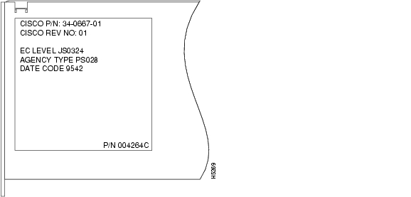
Figure 1 shows the label attached to the right side of the new AC-input power supplies.
If you are unable to determine if your AC-input power supplies need to be upgraded, based on the cosmetic differences shown in and , use this label to verify whether or not the AC-input power supply in your chassis needs to be upgraded.
If the part number on your AC-input power supplies is anything other than 34-0667-01, or later, upgrade to the new AC-input power supplies.
Figure 1 Label on the New AC-Input Power Supply (Right Side View)
Product Overview
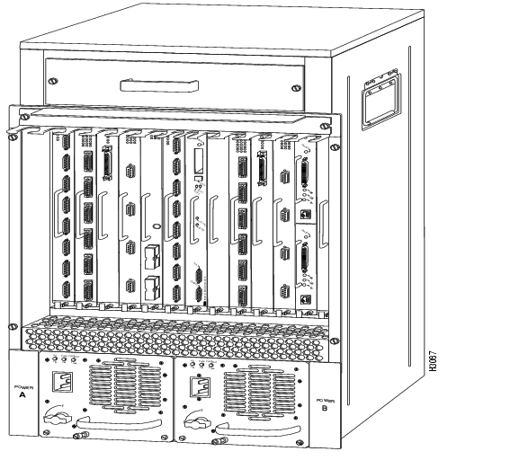
The AC-input power supply is optional equipment in the Cisco 7513. Power supplies reside in power supply bays in the rear of the router chassis. shows the Cisco 7513 with the older power supplies installed (Part Number 34-0049-01 or later).
Figure 2 Cisco 7513 (Rear-Panel View with the Older Power Supplies)
Figure 3 shows the Cisco 7513 with the new power supplies installed (Part Number 34-0667-01 or later).
Figure 3 Cisco 7513 (Rear-Panel View with the New Power Supplies)
Caution
The power A bay contains the first (or standard) power supply, and the power B bay contains the second (optional) supply, in systems with redundant power.
Power Supply Specifications
Table 1 lists the AC-input power supply specifications.
The specifications listed in Table 1 apply to the new and older AC-input power supplie
Table 1 Cisco 7513 AC-Input Power Supply Specifications
AC-input voltage
100 to 240 VAC1 , 20 amps maximum
Frequency
50 to 60 Hz
Internal DC voltages supplied and steady-state maximum current ratings
+5.2 VAC @ 200A
+12 VAC @ 35A
-12 VAC @ 3A
+24 VAC @ 8AInput power requirement
1600W
Power output
1200W with a maximum configuration and one or two AC-input power supplies
Heat dissipation
5465 Btu/hr
Weight
25 pounds (11.34 kilograms)
Cable supplied
12 American Wire Gauge (AWG), 20-amp2
1 VAC = volts direct current.
2 The Cisco 7513 requires a minimum of 20-amp service, with a 20-amp receptacle at the power source. The power cable supplied with the Cisco 7513 uses a 20-amp male plug.
Dual power supplies are automatically load-sharing and redundant, which means that you can install or replace a second power supply on line. During normal operation, dual supplies provide system power simultaneously (load share). When you remove one supply, the remaining supply immediately ramps up to provide full power and maintain uninterrupted power to the system. Whenever possible, connect each power supply to a separate AC source.
Caution
The AC-input power supply uses a power factor corrector (PFC) that automatically adjusts for the input voltage being supplied. The AC-input voltage range is 100 to 240 VAC. The power supplies are self-monitoring. Each supply monitors its own temperature and internal voltages. An internal fan in each power supply draws cooling air from the rear of the chassis, through the power supply, and out the front of the chassis. The power supply airflow is separate from that of the rest of the chassis.
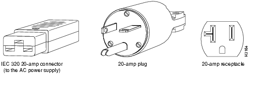
The Cisco 7513 requires a minimum of 20-amp service, with a 20-amp receptacle at the power source. The power cable supplied with the Cisco 7513 uses a 20-amp male plug. shows the cable connector plug and the 20-amp receptacle required to connect the 20-amp cable to your AC source.
Note
Figure 4 20-Amp AC Power Cable Connector and Plug, and 20-Amp Receptacle
Power Supply LED Indications
On the Cisco 7513 chassis front panel, the power A and power B LEDs go on when the power supply in the corresponding bay is installed and supplying power to the system. Both the power LEDs should be on in systems with redundant power.
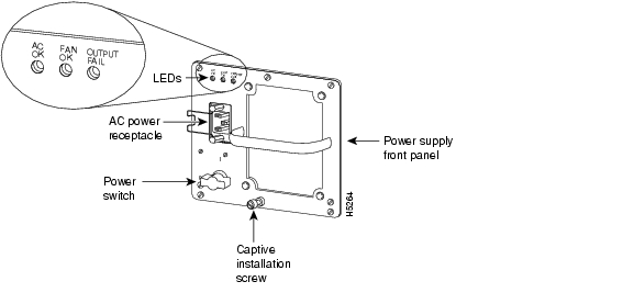
The power supply LEDs include the AC OK LED, the fan OK LED, and the output fail LED. (See Figure 5 for an illustration of the new AC-input power supply's LEDs.)
The AC OK LED is on when the input power is applied. The fan OK LED is normally on; however, it is off if the power supply fan fails. The output fail LED is normally off, but flashes at power on for a lamp test.
Figure 5 AC-Input Power Supply LEDs, New Power Supply
The output fail LED lights for either of the following reasons:
•
•
In systems with a single power supply, and in systems with redundant power when both power supplies are shutting down, the output fail LED lights momentarily as the system ramps down, but goes out when the power supply has completely shut down.
The power supplies feature the following three safety interlock features:
•
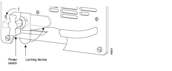
shows the locking mechanism on the older AC-input power supply. shows the locking mechanism on the new AC-input power supply.
Figure 6 On/off Switch Locking Mechanism on the Older AC-Input Power Supply
Figure 7 On/off Switch Locking Mechanism on the New AC-Input Power Supply
•
A spring clip on the AC receptacle supplies strain relief and prevents the power supply power cable from being pulled out accidentally.Environmental Monitoring and Reporting Functions
The environmental monitoring and reporting functions, controlled by the chassis interface board, enable you to maintain normal system operation by identifying and resolving adverse conditions prior to loss of operation. The environmental monitoring functions constantly monitor the internal chassis air temperature and DC supply voltages and currents. Each power supply monitors its own voltage and temperature and shuts itself down if it detects a critical condition within the power supply. If conditions reach shutdown thresholds, the system shuts down to avoid equipment damage from excessive heat. The reporting functions periodically log the values of measured parameters so that you can retrieve them for analysis later, and the reporting functions display warnings on the console if any of the monitored parameters exceed defined thresholds.
In addition to monitoring internal temperature and voltage levels, the system also monitors the blower. If the blower fails, the system displays a warning message on the console. If the blower is still not operating properly after two minutes, the system shuts down to protect the internal components against damage from excessive heat.
Environmental Monitoring
Three sensors on the Route Switch Processor (RSP2) monitor the temperature of the cooling air that flows through the processor slots: inlet, hotpoint, and exhaust. The sensors are located at the bottom, center, and top of the RSP2, when facing the interface processor end of the chassis and viewing the RSP2 as it is installed.
The power supply uses the Normal, Critical, and Warning levels to monitor DC voltages. Table 2 lists temperature thresholds for the three processor-monitored levels. Table 3 lists the DC power thresholds for the Normal and Critical (power-supply-monitored) levels.
•
•
•
•
•
–
–
–
•
If the air temperature exceeds a defined threshold, the system processor displays warning messages on the console terminal and, if the temperature exceeds the shutdown threshold, it shuts down the system. The system stores the present parameter measurements for both temperature and DC voltage in NVRAM, so that you can retrieve it later as a report of the last shutdown parameters.
The power supplies monitor internal power supply temperature and voltages. A power supply is either within tolerance (Normal) or out of tolerance (Critical or Warning levels), as shown in Table 3. If an internal power supply temperature or voltage reaches a critical level, the power supply shuts down without any interaction with the system processor.
If the system detects that AC or DC input power is dropping, but it is able to recover before the power supply shuts down, it logs the event as an intermittent power failure. The reporting functions display the cumulative number of intermittent power failures logged since the last power up.
Environmental Reports
The system displays warning messages on the console if chassis interface-monitored parameters exceed a desired threshold or if a blower failure occurs. You can also retrieve and display environmental status reports with the show environment, show environment all, show environment last and show environment table commands. Parameters are measured and reporting functions are updated every 60 seconds. A brief description of each of these commands follows.
Caution
The show environment command display reports the current environmental status of the system. The report displays parameters that are out of the normal values. No parameters are displayed if the system status is normal. The example that follows shows the display for a system in which all monitored parameters are within Normal range. Following is sample output of the show env command:
Router# show envAll measured values are normalIf the environmental status is not normal, the system reports the worst-case status level in the last line of the display.
The show environment last command retrieves and displays the NVRAM log showing the reason for the last shutdown (if the shutdown was related to voltage or temperature) and the environmental status at that time. Air temperature is measured and displayed; the DC voltages supplied by the power supply are also displayed. Following is sample output of the show env last command:
Router# show env lastRSP(6) Inlet previously measured at 27C/80FRSP(6) Hotpoint previously measured at 38C/100FRSP(6) Exhaust previously measured at 31C/87F+12 Voltage previously measured at 12.17+5 Voltage previously measured at 5.19-12 Voltage previously measured at -12.17+24 Voltage previously measured at 23.40The show environment table command displays the temperature and voltage thresholds for each of the three RSP2 temperature sensors, for each monitored status level: low critical, low warning, high warning, and high critical, which are the same as those listed in Tables 2 and 3. The slots in which the RSP2 can be installed are indicated in parentheses (6 and 7). Also listed are the shutdown thresholds for the processor boards and power supplies. Following is sample output of the show env table command:
Router# show env tableSample Point LowCritical LowWarning HighWarning HighCriticalRSP(6) Inlet 44C/111F 50C/122FRSP(6) Hotpoint 54C/129F 60C/140FRSP(6) ExhaustRSP(7) Inlet 44C/111F 50C/122FRSP(7) Hotpoint 54C/129F 60C/140FRSP(7) Exhaust+12 Voltage 10.76 11.37 12.64 13.24+5 Voltage 4.49 4.74 5.25 5.52-12 Voltage -10.15 -10.76 -13.25 -13.86+24 Voltage 19.06 21.51 26.51 28.87Shutdown boards at 101C/213FShutdown power supplies at 101C/213F
Note
The show environment all command displays an extended report that includes the arbiter type, backplane type, power supply type (AC or DC), wattage and status, the number and type of intermittent power failures (if any) since the system was last powered on, and the currently measured values at the RSP2 temperature sensors and the DC-input lines. The show environment all command also displays a report showing which slots in the Cisco 7513 are occupied (indicated by an X) and which are empty.
Note
Active fault conditions are indicated when the blower or power supply has failed or is not present (as "Blower #3" indicates in the following example). The system expects to see three blowers or fans in the Cisco 7513: the main system blower, and one fan in each power supply. The system blower is designated #1, the power supply fan in power bay A is #2, and the power supply fan in power bay B is #3. The active fault condition in the following example shows that there is no power supply installed in power bay B because the display indicates that power supply #2 (in power bay B) is removed. System blower speed is displayed as a percentage of maximum.
There are four active trip points: restart OK, temperature warning, board shutdown, and power supply shutdown. (There are no active trip points shown in the following example.) The soft shutdowns refer to the number of times the system will reset itself before it executes a complete chassis (or hard) shutdown.
The current temperature measurements at the three RSP2 sensors are displayed as inlet, hotpoint, and exhaust. The shutdown temperature source is the hotpoint sensor, which is located toward the center of the RSP2. System voltage measurements are also displayed, followed by the system current measurements and power supply wattage calculation. Following is sample output of the show env all command:
Router# show env allArbiter type 1, backplane type 7513 (id 2)Power supply #1 is 1200W AC (id 1), power supply #2 is removed (id 7)Active fault conditions: Blower #3Fan speed is 50%Active trip points: none15 of 15 soft shutdowns remaining before hard shutdown10123456789012Dbus slots: XX XXXX XXXXinlet hotpoint exhaustRSP(6) 24C/75F 35C/95F 29C/84FShutdown temperature source is 'hotpoint' slot6 (requested slot6)+12V measured at 12.17+5V measured at 5.19-12V measured at -12.26+24V measured at 24.44+2.5 reference is 2.49PS1 +5V Current measured at 42.35 A (capacity 200 A)PS1 +12V Current measured at 6.86 A (capacity 35 A)PS1 -12V Current measured at 0.55 A (capacity 3 A)PS1 output is 296 WInstallation Safety, ESD Precautions, and Tools Required
Before you begin this installation, review the safety guidelines in this section to avoid injuring yourself or damaging the equipment. This section also provides power requirements to consider if you are adding a second power supply to your system for redundant power, and lists of the tools and parts you need to perform this installation.
Safety Guidelines
The following guidelines will help to ensure your safety and protect the equipment. This list is not inclusive of all potentially hazardous situations, so be alert.
•
•
•
•
•
•
Safety with Electricity
You can remove or install a redundant (second) power supply without turning off the other supply. Before removing a redundant power supply, ensure that the first supply is powered on to ensure uninterrupted operation.
Follow these basic guidelines when working with any electrical equipment:
•
•
•
•
•
•
In addition, use the guidelines that follow when working with any equipment that is connected to telephone wiring or other network cabling.
•
•
•
•
Preventing Electrostatic Discharge Damage
Electrostatic discharge (ESD) damage, which can occur when electronic boards or components are handled improperly, can result in complete or intermittent failures.
Following are guidelines for preventing ESD damage:
•
•
•
•
Warning
Tools and Parts Required
You need the following tools to install or replace a power supply:
•
•
•
•
•
•
Note
•
Note
Before beginning the power supply installation, check the installation screws on all power supplies and check the area around the power supply bays to determine which tools you will need. The new power supply and the power cable, that you supply, are the only parts you need to complete this installation.
If you remove a power supply and leave the bay empty, install a power supply blank in the empty power supply bay. (See .) Chassis shipped with a single power supply include a power supply blank installed in the empty power supply bay.
Circuit Protection Requirements
Based on the NFPA 70 National Electrical Code, you should use a 35A overcurrent protector to meet the requirement for the overcurrent protector size of 125 percent of the load current, which is approximately 27A. An overcurrent protector rated for 30A can be used only if it has been listed by the safety agency for operation at 100 percent of its rating.
Replacing Older AC-Input Power Supplies
The following procedures describe removing the older power supplies from your Cisco 7513 (Part Number 34-0049-01 or later), and installing new power supplies (Part Number 34-0667-01 or later).
All power supplies rest on the floor of the chassis under the card cage.
Note
Warning
Removing Older Power Supplies
Follow these steps to remove an older power supply (Part Number 34-0049-01 or later):
Step 1
Step 2
Warning
Step 3
Step 4
Figure 8 Removing an Older Power Supply
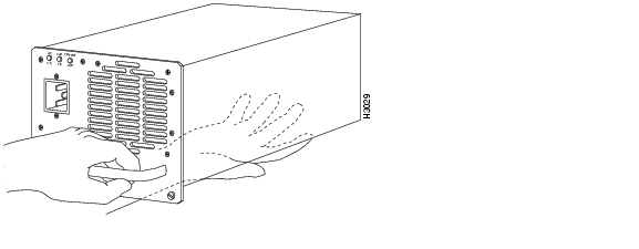
Step 5
Figure 9 Supporting the Older Power Supply
Step 6
Caution
Figure 10 Power Supply Blank
This completes the removal procedure for the older power supplies.
Installing New Power Supplies
Follow these steps to install a new power supply (Part Number 34-0667-01 or later):
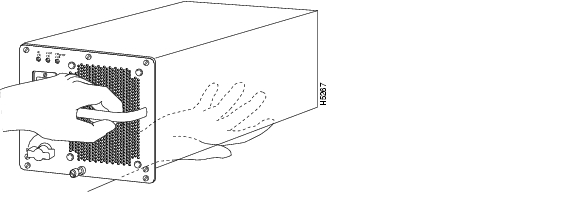
Step 1
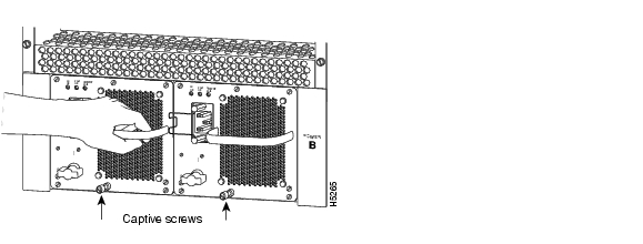
Figure 11 Supporting the New Power Suppl
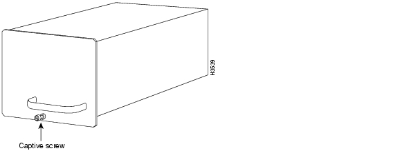
Step 2
Figure 12 Location of Captive Installation Screws on the New Power Supply
Step 3
Warning
Note
Step 4
Step 5
This completes the installation procedure for the new power supplies.
Proceed to the following section " Checking the New Power Supply Installation" to apply power and check the installation.
Checking the New Power Supply Installation
To complete the installation, turn each power supply on and observe its LEDs to verify that it is operating properly.
Step 1
Step 2
•
•
•
•
Step 3
Step 4
If the power supply switch resists, it is probably not fully inserted into the bay. Turn the power switch fully counterclockwise to OFF (O), pull the power supply out of the bay about two inches, then push the power supply firmly back into the slot. Do not slam the supply into the slot—doing so can damage the connectors on the supply and the backplane. Tighten the captive installation screw before proceeding.
Step 5
•
•
•
•
•
If the power supply fails to operate properly after several attempts to initialize it, contact a service representative for assistance. If the power supply fails (and you need to order a replacement) and you did not record the type of power supply in your chassis, you will have to check the chassis in order to make this determination.
Timesaver
This completes the power supply upgrade.
Refer to the Cisco 7513 Hardware Installation and Maintenance publication for installation troubleshooting procedures, and to the appropriate software configuration publication for descriptions and examples of software configuration features and commands.
Power Cord Warning
Related Documentation
See the following for a listing of additional documentation for the Cisco 7500 Series routers:
•
•
•
•
Obtaining Documentation
Cisco documentation and additional literature are available on Cisco.com. Cisco also provides several ways to obtain technical assistance and other technical resources. These sections explain how to obtain technical information from Cisco Systems.
Cisco.com
You can access the most current Cisco documentation at this URL:
http://www.cisco.com/univercd/home/home.htm
You can access the Cisco website at this URL:
You can access international Cisco websites at this URL:
http://www.cisco.com/public/countries_languages.shtml
Ordering Documentation
You can find instructions for ordering documentation at this URL:
http://www.cisco.com/univercd/cc/td/doc/es_inpck/pdi.htm
You can order Cisco documentation in these ways:
•
http://www.cisco.com/en/US/partner/ordering/index.shtml
•
Documentation Feedback
You can send comments about technical documentation to bug-doc@cisco.com.
You can submit comments by using the response card (if present) behind the front cover of your document or by writing to the following address:
Cisco Systems
Attn: Customer Document Ordering
170 West Tasman Drive
San Jose, CA 95134-9883We appreciate your comments.
Obtaining Technical Assistance
For all customers, partners, resellers, and distributors who hold valid Cisco service contracts, Cisco Technical Support provides 24-hour-a-day, award-winning technical assistance. The Cisco Technical Support Website on Cisco.com features extensive online support resources. In addition, Cisco Technical Assistance Center (TAC) engineers provide telephone support. If you do not hold a valid Cisco service contract, contact your reseller.
Cisco Technical Support Website
The Cisco Technical Support Website provides online documents and tools for troubleshooting and resolving technical issues with Cisco products and technologies. The website is available 24 hours a day, 365 days a year at this URL:
http://www.cisco.com/techsupport
Access to all tools on the Cisco Technical Support Website requires a Cisco.com user ID and password. If you have a valid service contract but do not have a user ID or password, you can register at this URL:
http://tools.cisco.com/RPF/register/register.do
Submitting a Service Request
Using the online TAC Service Request Tool is the fastest way to open S3 and S4 service requests. (S3 and S4 service requests are those in which your network is minimally impaired or for which you require product information.) After you describe your situation, the TAC Service Request Tool automatically provides recommended solutions. If your issue is not resolved using the recommended resources, your service request will be assigned to a Cisco TAC engineer. The TAC Service Request Tool is located at this URL:
http://www.cisco.com/techsupport/servicerequest
For S1 or S2 service requests or if you do not have Internet access, contact the Cisco TAC by telephone. (S1 or S2 service requests are those in which your production network is down or severely degraded.) Cisco TAC engineers are assigned immediately to S1 and S2 service requests to help keep your business operations running smoothly.
To open a service request by telephone, use one of the following numbers:
Asia-Pacific: +61 2 8446 7411 (Australia: 1 800 805 227)
EMEA: +32 2 704 55 55
USA: 1 800 553 2447For a complete list of Cisco TAC contacts, go to this URL:
http://www.cisco.com/techsupport/contacts
Definitions of Service Request Severity
To ensure that all service requests are reported in a standard format, Cisco has established severity definitions.
Severity 1 (S1)—Your network is "down," or there is a critical impact to your business operations. You and Cisco will commit all necessary resources around the clock to resolve the situation.
Severity 2 (S2)—Operation of an existing network is severely degraded, or significant aspects of your business operation are negatively affected by inadequate performance of Cisco products. You and Cisco will commit full-time resources during normal business hours to resolve the situation.
Severity 3 (S3)—Operational performance of your network is impaired, but most business operations remain functional. You and Cisco will commit resources during normal business hours to restore service to satisfactory levels.
Severity 4 (S4)—You require information or assistance with Cisco product capabilities, installation, or configuration. There is little or no effect on your business operations.
Obtaining Additional Publications and Information
Information about Cisco products, technologies, and network solutions is available from various online and printed sources.
•
http://www.cisco.com/go/marketplace/
•
http://cisco.com/univercd/cc/td/doc/pcat/
•
•
•
http://www.cisco.com/go/iqmagazine
•
•
http://www.cisco.com/en/US/learning/index.html
This document is to be used in conjunction with the documents listed in the "Related Documentation" section ..
Copyright © 2004 Cisco Systems, Inc. All rights reserved.
![]()
![]()
![]()
![]()
![]()
![]()
![]()
![]()
Posted: Wed Jul 21 10:45:37 PDT 2004
All contents are Copyright © 1992--2004 Cisco Systems, Inc. All rights reserved.
Important Notices and Privacy Statement.