|
|

Table Of Contents
Fourth Generation Versatile Interface Processor (VIP4) Installation and Configuration Guide
How to Identify the VIP4 Model
VIP4 and Port Adapter Compatibility
Electrical Equipment Guidelines
Preventing Electrostatic Discharge Damage
Guidelines for VIP4 Removal and Installation
Performing a Basic Configuration
Checking the VIP4 Installation
Verifying the VIP4 Installation
Using show Commands to Verify the VIP4 Status
Using show Commands to Display Interface Information
Using the ping Command to Verify Network Connectivity
Checking the VIP4 Memory Upgrade
Obtaining Technical Assistance
Fourth Generation Versatile Interface Processor (VIP4) Installation and Configuration Guide
Product Numbers: VIP4-50=, VIP4-80=, MEM-VIP4-64M-SD=, MEM-VIP4-128M-SD=, MEM-VIP4-256M-SD=
Introduction
This guide provides instructions for installing, configuring, and maintaining the fourth-generation Versatile Interface Processor (VIP4). The VIP4 operates with the Cisco 7505, Cisco 7507, Cisco 7507-MX, Cisco 7513, Cisco 7513-MX, and the Cisco 7576 routers with the Route Switch Processor (RSP1, RSP2, RSP4, RSP4+, or RSP8), and with the Cisco 7000 series routers using the 7000 Series Route Switch Processor (RSP7000) and 7000 Series Chassis Interface (RSP7000CI). See the "Software Requirements" section for specific compatibility requirements.
The VIP4 supports online insertion and removal (OIR), which allows you to remove and replace a VIP4 without first shutting down the system. Online insertion and removal maximizes router availability by letting you add or remove VIP4s during system operation. See the "Guidelines for VIP4 Removal and Installation" section for more information on removing and installing the VIP4.
The VIP4 supports LAN and WAN port adapters (PAs), including Fast Ethernet, T1/E1, High-Speed Serial Interface (HSSI), T3/E3, T3/E3 ATM, multichannel T1/E1, multichannel T3/E3, OC-3 ATM, Packet over SONET (POS), and OC-12 ATM. For a list of supported port adapters, refer to the "VIP4 and Port Adapter Compatibility" section.
The VIP4 port adapters do not support OIR, so when removing or inserting a port adapter, the system must be shut down first. The VIP42 must be removed from its interface processor slot before removing or installing a port adapter.
For complete descriptions of interface subcommands and the configuration options available for VIP4-related interfaces, refer to the configuration note for each of the port adapters installed on your VIP4 and to the appropriate Cisco IOS software configuration publications. (See the "Related Documentation" section.)
Contents
This guide includes the following sections:
•
Related Documentation, page 2
•
•
•
•
•
Related Documentation
Your router and the Cisco IOS software running on it contain extensive features and functionality, which are documented in the following resources:
•
For configuration information and support, refer to the modular configuration and modular command reference publications in the Cisco IOS software configuration documentation set that corresponds to the software release installed on your Cisco hardware.
Note
•
For hardware installation and maintenance information on the Cisco 7000 series routers, refer to the Cisco 7000 Hardware Installation and Maintenance manual that shipped with your router.
•
For hardware installation and maintenance information on the Cisco 7500 series routers, refer to the Cisco 7500 Installation and Configuration Guide that shipped with your router.
•
–
–
–
•
For port adapter information and maintenance information, refer to the specific port adapter installation and configuration guide. See the port adapter index online at http://www.cisco.com/univercd/cc/td/doc/product/core/cis7505/portadpt/index.htm.
•
–
–
VIP4 Overview
This section describes the VIP4 and discusses VIP4-specific features and functions, such as:
•
•
What is the VIP4?
The VIP4 is the fourth generation of Versatile Interface Processors for use with Cisco 7500 or Cisco 7000 series routers. The VIP4 installs in any interface processor slot on your router, as noted below:
•
•
•
•
•
•
For more information on interface processor slots on your router, refer to the Cisco 7500 Series Installation and Configuration Guide or the appropriate Quick Start Guide for the Cisco 7500 series routers, or refer to Cisco 7000 Hardware Installation and Maintenance manual for the Cisco 7000 series routers.
How to Identify the VIP4 Model
There are two different versions of the VIP4: the VIP4-50 and the VIP4-80. Both VIP4 versions support two single-width port adapters or one dual-width port adapter and identical ECC-protected memory expansion options. Each VIP4 operates with the Cisco 7505, Cisco 7507, Cisco 7507-MX, Cisco 7513, Cisco 7513-MX, and the Cisco 7576 routers.
Using the show diag command, you can distinguish between the VIP4-50 and VIP4-80, as indicated in the following example, and in Table 1.
Table 1 Distinguishing the VIP4 Models
0x31
VIP4-50
0x22
VIP4-80
In the example below, the VIP is a VIP4-80:
Router# show diag 1Slot 1:Physical slot 1, ~physical slot 0xE, logical slot 1, CBus 0Microcode Status 0x4Master Enable, LED, WCS LoadedBoard is analyzedPending I/O Status:NoneEEPROM format version 1VIP4-80 RM7000 controller, HW rev 2.01, board revision A0Serial number:14773010 Part number:73-3143-02Test history:0x00 RMA number:00-00-00Flags:cisco 7000 board; 7500 compatibleEEPROM contents (hex):0x20:01 22 02 01 00 E1 6B 12 49 0C 47 02 00 00 00 000x30:50 06 00 00 00 00 00 00 00 00 00 00 00 00 00 00Slot database information:Flags:0x4 Insertion time:0x5168 (2w1d ago)Controller Memory Size:64 MBytes CPU SDRAM, 64 MBytes PacketSDRAMPA Bay 0 Information:Fast-Ethernet PA, 1 ports, 100BaseTX-ISLEEPROM format version 1HW rev 1.00, Board revision A0Serial number:03536381 Part number:73-1688-03PA Bay 1 Information:Dual Port Fast Ethernet (RJ45), 2 portsEEPROM format version 4HW rev 1.00, Board revision 04Serial number:MIC043929WV Part number:73-5419-03--Boot log begin--Cisco Internetwork Operating System SoftwareIOS (tm) VIP Software (SVIP-DW-M), Version 12.0(16.5)S, EARLY DEPLOYMENTMAINTENANCE INTERIM SOFTWARETAC Support:http://www.cisco.com/cgi-bin/ibld/view.pl?i=supportCopyright (c) 1986-2001 by cisco Systems, Inc.Compiled Thu 29-Mar-01 16:33 by ninahungImage text-base:0x60010938, data-base:0x60340000--Boot log end--Table 2 outlines features of the VIP4 models, and Table 3 provides a list of the VIP4 internal components.
Note
Table 2 VIP4 Model Features
VIP4-50
~140,000
750+ MB
Yes;
Moderate to high DSWDistributed switching
Moderate link utilization
Cisco Express Forwarding (CEF)VIP4-80
~170,000
750+ MB
Yes;
Very high DSWHigh distributed switching performance
Multiple high-speed PAs with high link utilization
Extensive use of distributed IP services
Cisco Content Networking (CCN)
1 PPS = Packets per Second
Table 3 VIP4 Internal Components
(see Figure 1)CPU (for VIP4-50)
200 megahertz (MHz)
internal operating frequencyReduced Instruction Set Computer (RISC), IPSR5271 processor
CPU
CPU (for VIP4-80)
250 megahertz (MHz)
internal operating frequencyReduced Instruction Set Computer (RISC), MIPS R7000 processor
CPU
SDRAM DIMMs 1
(program or CPU memory)64 (default), 128, or 256 MB
100-MHz synchronous dynamic random-access memory (SDRAM) as CPU memory contained on dual in-line memory modules (DIMMs)
U1
SDRAM DIMMs 1
(packet memory)64 MB
100-MHz synchronous dynamic random-access memory (SDRAM) as packet memory contained on dual in-line memory modules (DIMMs)
U5
1 8-bit error correction code (ECC), rather than byte parity, for single error-bit correction and double error-bit detection
Specifications
The VIP4 physical specifications are listed in Table 4.
VIP4 Port Adapter Overview
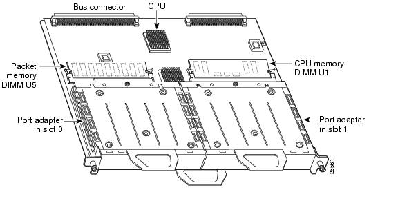
The VIP4, a single motherboard, supports up to two single-width port adapters, or one dual-width port adapter. Figure 1 shows a VIP4 with two installed single-width port adapters. A dual-width port adapter occupies both port adapter slots (not shown).
Note
Note
Figure 1 VIP4 with Two Single-Width Port Adapters—Horizontal Orientation Shown
VIP4 and Port Adapter Compatibility
For more information on the available port adapters supported by the VIP4, refer to the Cisco Product Catalog online, or contact a Cisco sales representative in your area. For more information on a specific port adapter, refer to the specific port adapter installation and configuration guide. The port adapters, including part numbers for ordering, are listed in the Cisco Port Adapter Documentation flyer. This document is available online at http://www.cisco.com/univercd/cc/td/doc/product/core/12939paf.htm or in print (DOC-7812939).
Note
Table 5 identifies the port adapters supported by the VIP4 at the time of this writing, and Table 6 identifies the interface processors and service adapters that are supported by the VIP4.
Note
Table 5 List of Port Adapters Supported by VIP4
PA-A3-T3
ATM DS3 port adapter, enhanced
1
Single
PA-A3-E3
ATM E3 port adapter, enhanced
1
Single
PA-A3-8T1IMA
ATM inverse multiplexer over ATM port adapter
8
Single
PA-A3-8E1IMA
ATM inverse multiplexer over ATM port adapter
8
Single
PA-A3-OC3MM
ATM OC-3c/STM-1 multimode, enhanced
1
Single
PA-A3-OC3SMI
ATM OC-3c/STM-1 single-mode (IR), enhanced
1
Single
PA-A3-OC3SML
ATM OC-3c/STM-1 single-mode (LR), enhanced
1
Single
PA-A3-OC12-MM
ATM OC-12/STM-4 single-mode (IR); multimode
1
Dual
PA-A3-OC12-SMI
ATM OC-12/STM-4 single-mode (IR); multimode
1
Dual
PA-POS-OC3- MM
Single-wide OC-3c/STM-1
1
Single
PA-POS-OC3- SMI
Single-wide OC-3c/STM-1
1
Single
PA-POS-OC3- SML
Single-wide OC-3c/STM-1
1
Single
PA-A1-OC3SM
ATM OC3 Single-Mode Intermediate Reach
1
Single
PA-A1-OC3MM
ATM OC3 Multimode
1
Single
PA-FE-TX
Fast Ethernet 100BaseTX
1
Single
PA-FE-FX
Fast Ethernet 100BaseFX
1
Single
PA-2FE-TX
Dual-Port Fast Ethernet 100BaseTX
2
Single
PA-2FE-FX
Dual-Port Fast Ethernet 100BaseFX
2
Single
PA-4E
Ethernet 10BaseT
4
Single
PA-8E
Ethernet 10BaseT
8
Single
PA-F-MM
FDDI Multimode
1
Single
PA-F-SM
FDDI Single-Mode
1
Single
PA-FD-MM
FDDI Full Duplex Multimode
1
Single
PA-FD-SM
FDDI Full Duplex Single-mode
1
Single
PA-4T+
Serial, Enhanced
4
Single
PA-8T-V35
Serial, V.35
8
Single
PA-8T-232
Serial, RS232
8
Single
PA-8T-X21
Serial, X.21
8
Single
PA-T3/PA-T3+
T3 Serial Interface/T3 Serial Interface enhanced
1
Single
PA-2T3/ PA-2T3+
T3 Serial Interface/T3 Serial Interface enhanced
2
Single
PA-E3
E3 Serial Interface
1
Single
PA-2E3
E3 Serial Interface
2
Single
PA-4E1G/75
E1 G.703 Serial (75 ohm/Unbalanced)
4
Single
PA-4E1G/120
E1 G.703 Serial (120 ohm/Balanced)
4
Single
PA-MC-T3
Multichannel T3
1
Single
PA-MC-E3
Multichannel E3
1
Single
PA-MC-2T1
Multichannel DS1/PRI T1 (100 ohm)
2
Single
PA-MC-4T1
Multichannel DS1/PRI T1 (100 ohm)
4
Single
PA-MC-8T1
Multichannel DS1/PRI T1 (100 ohm)
8
Single
PA-MC-2T3+
Multichannel with two T3 interfaces
2
Single
PA-MC-8DSX1
Multichannel DS1/PRI T1 (100 ohm)
8
Single
PA-MC-2E1/120
Multichannel E1 with G.703 120-ohm interface
2
Single
PA-MC-8E1/120
Multichannel E1 with G.703 120-ohm interface
8
Single
PA-MC-STM-1MM
Multichannel STM-1 Port Adapter
1
Single
PA-MC-STM-1SMI 1
Multichannel STM-1 Port Adapter
1
Single
PA-H
HSSI
1
Single
PA-2H
HSSI
2
Single
PA-VXC-2TE1
High-Capacity Digital Voice
2
Single
PA-VXC-2TE1+
High-Capacity Digital Voice
2
Single
PA-VXB-2TE1
Moderate-Capacity Digital Voice
2
Single
PA-VXB-2TE1+
Moderate-Capacity Digital Voice
2
Single
PA-SRP-OC12MM 2
Multimode fiber
2
Dual
PA-SRP-OC12SMI 2
Single-mode fiber, intermediate reach
2
Dual
PA-SRP-OC12SML 2
Single-mode fiber, long reach
2
Dual
PA-SRP-OC12SMX 2
Single-mode fiber, extended reach
2
Dual
1 Supported on VIP4-80 only.
2 Requires Cisco IOS release 12.1(12)E or later, or Cisco IOS release 12.1(21)S or later.
Table 6 List of Interface Processors Supported by VIP4
GEIP
Gigabit Ethernet Interface Processor
1
GEIP+
Gigabit Ethernet Interface Processor, enhanced
1
Note
Installation Prerequisites
This section provides installation prerequisites to ensure a successful VIP4 installation, and includes the following sections:
•
•
Software Requirements
The minimum Cisco IOS Release requirements for VIP4-50 and VIP4-80 are listed in Table 7. For configuration information and support, refer to the modular configuration and modular command reference publications in the Cisco IOS software configuration documentation set that corresponds to the software release installed on your Cisco hardware.
Note
Traffic Management
•
•
Hardware Requirements
The VIP4 is a single motherboard. It operates with:
•
•
•
Note
Microcode Overview
The VIP4 microcode (firmware) is an image that provides card-specific software instructions. A programmable read-only memory (PROM) device on the VIP4 contains a default microcode boot image that assists the system in finding and loading the microcode image from the Cisco IOS bundle or Flash memory. The router supports downloadable microcode, which enables you to upgrade microcode versions by downloading new microcode images, storing them in system Flash memory, and instructing the system to load its image from Flash memory. You can store multiple images for an interface type and, with a configuration command, instruct the system to load any one of them or the default microcode image.
The microcode boot image in the PROM initializes the VIP4 and then assists downloading the VIP4 microcode image. All interfaces of the same type (VIP4, and so on) will load the same microcode image, either from the microcode image bundled with the Cisco IOS or from an image stored in system Flash memory. Although multiple microcode versions for a specific interface type can be stored concurrently in Flash memory, only one image can load at startup.
The show controllers cbus command displays the currently loaded and running microcode version for each interface processor and VIP4. The show startup-config EXEC command shows the current system instructions for loading microcode at startup.
Software and interface processor microcode images are carefully optimized and bundled to work together. Overriding the bundle can result in system incompatibilities. We recommend that you use the microcode included in the software bundle. For a complete description of microcode and downloading procedures, refer to the "Upgrading VIP4 Microcode" section.
ROM Monitor Overview
The VIP4 read-only memory (ROM) monitor, known as Rommon, is firmware. It runs a brief set of system diagnostics, initializes the VIP4 hardware, and downloads a copy of the Cisco IOS image.The ROM monitor loads the Cisco IOS image from Flash memory or from a TFTP server. While multiple Cisco IOS images can be stored in RSP Flash memory, just one can be loaded at system startup.
The VIP4 ROM monitor functions similarly to the boot loader image on the RSP, which runs a copy of the Cisco IOS image. The boot loader image allows the router to access the Cisco IOS image when powering up or initializing the system.
Tools and Parts Required
You need the following tools and parts to install or upgrade a VIP4:
•
•
•
Note
If you need additional equipment, contact a service representative for ordering information.
Agency Approvals
The VIP4 is designed to comply with and meet the following agency approvals:
Safety Guidelines
Following are safety guidelines that you should follow when working with any equipment that connects to electrical power or telephone wiring.
Safety Warnings
Safety warnings appear throughout this publication in procedures that, if performed incorrectly, may harm you. A warning symbol precedes each warning statement.
Electrical Equipment Guidelines
Follow these basic guidelines when working with any electrical equipment:
•
•
•
•
•
•
Telephone Wiring Guidelines
Use the following guidelines when working with any equipment that is connected to telephone wiring or to other network cabling:
•
•
•
•
Preventing Electrostatic Discharge Damage
Electrostatic discharge (ESD) damage, which can occur when electronic cards or components are improperly handled, results in complete or intermittent failures.
Use the following guidelines for preventing ESD damage:
•
•
•
•
•
•
•
•
Caution
VIP4 Installation Procedures
This section includes procedures for VIP4 installation in the Cisco 7500 series or Cisco 7000 series routers, and includes information on the following topics:
•
•
VIP4 installation is the same for each router model, except where otherwise noted.
The VIP4 is oriented horizontally in the Cisco 7010 and Cisco 7505 routers, and vertically in the Cisco 7000, Cisco 7507, Cisco 7507-MX, Cisco 7513, Cisco 7513-MX, and Cisco 7576 routers.
Each unused interface processor slots must contain an interface processor filler (an interface processor carrier without a printed circuit board) to keep dust out of the router and to maintain proper airflow through the interface processor compartment.
Note
Proceed to the "Removing a VIP4" section if you plan to replace a VIP4 with another VIP4, or if you plan to install a new VIP4, in which case you would first remove an existing interface processor or interface processor filler from an unused slot.
To install or remove a port adapter, see the "Installing or Replacing a Port Adapter on a VIP4" section on page 35.
Guidelines for VIP4 Removal and Installation
This section describes the correct procedures to avoid unnecessary board failures.
Caution
Note
You can remove and replace interface processors (such as the VIP4) while the system is operating, with minimal disruption.When an interface processor is added or removed, the switching complex is paused while the internal data structures are rebuilt for the new interface configuration. During this time, packets are not switched through the system. However, routing adjacencies and forwarding entries are maintained throughout the insertion and removal process.
After a VIP4 is reinstalled, the system brings online only interfaces that match the current configuration and were previously configured as up; all others require that you configure them with the configure command. For more information on the configure command, refer to the documentation of the specific port adapter or interface processor that you are installing.
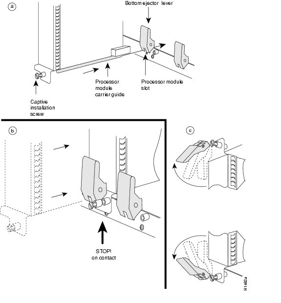
Figure 2 shows a detail of the ejector lever mechanism on the ends of the interface processor. Use the ejector levers when removing an interface processor to ensure that the backplane connector pins disconnect from the interface processor in the sequence expected by the system. Any interface processor that is only partially connected to the backplane can hang the bus.
Figure 2 Ejector Levers and Captive Installation Screws on the VIP4—Vertical Orientation Shown
Note
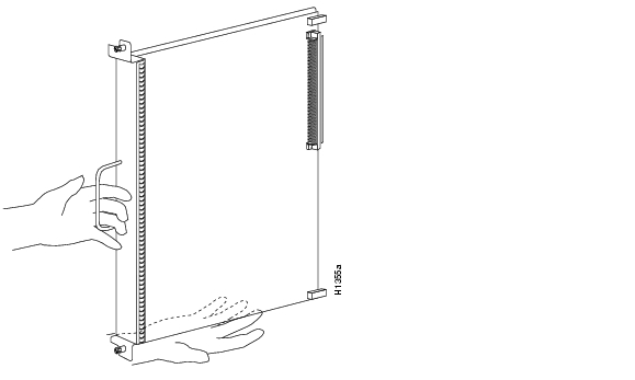
Figure 3 Handling Interface Processors—Vertical Orientation Shown
Caution
Removing a VIP4
This section describes the procedure for removing a VIP4, an interface processor, or an interface processor filler, and replacing it with a new VIP4. Please read the "Guidelines for VIP4 Removal and Installation" section before proceeding with this procedure.
Note
Caution
For more information on HSA or HA, refer to your RSP Installation and Configuration Guide.
If your router does not have the HSA or HA feature enabled, perform only Step 4 through Step 7 in the following procedure. If the router has the HSA or HA feature enabled with an RSP2 configured as the system standby, we recommend that you perform all the steps in the following procedure:
Step 1
Step 2
Step 3
Step 4
Step 5
Caution
Step 6
•
•
Step 7
Note
Step 8
Step 9
This completes the procedure for removing a VIP4 or interface processor from your Cisco 7000 series or Cisco 7500 series router. Proceed to the section " Installing a VIP4."
Installing a VIP4
This section describes the procedure for installing a VIP4. The VIP4 slides into an open interface processor slot and connects directly to the backplane. The interface processors are keyed to guide pins on the backplane, so the VIP4 can be installed only in an interface processor slot. Please read the "Guidelines for VIP4 Removal and Installation" section, if you have not already done so, before proceeding.
Note
Figure 2 shows the functional details of inserting an interface processor and using the ejector levers. Figure 3 shows proper handling of an interface processor during installation.
Caution
Use the following procedure to install a new VIP4:
Step 1
Step 2
Step 3
Caution
Step 4
Step 5
Caution
Step 6
Step 7
Caution
This completes the procedure for installing a VIP4 in a Cisco 7500 series or Cisco 7000 series router. (For the procedures for installing or removing a port adapter on your VIP4, see the "Installing or Replacing a Port Adapter on a VIP4" section on page 35.)
Performing a Basic Configuration
For complete descriptions of interface subcommands and the configuration options available for VIP4-related interfaces, refer to the configuration note for each of the port adapters installed on your VIP4 and to the appropriate Cisco IOS software configuration publications. (See the "Related Documentation" section.)
Checking the VIP4 Installation
This section describes the procedures you can use to verify your VIP4 installation, and includes information on the following topics:
•
•
•
•
You can use the configure command to configure the interfaces on the port adapters installed on your VIP4. To use the configure command, enter the privileged level of the EXEC command interpreter with the enable command, as shown below. The system prompts you for a password if one has been set.
The system prompt for the privileged level ends with a pound sign (#) instead of an angle bracket (>). Use the following procedure to enter the privileged level:
Step 1
Router> enablePassword:Step 2
Step 3
Router#Verifying the VIP4 Installation
After you install the VIP4 and connect cables (using connection procedures in the respective subsections of the configuration notes that shipped with your port adapters), verify the installation by observing the port adapter LED states and the information displayed on your console terminal.
Note
When the system has reinitialized all interfaces, the enabled LED on the VIP4 port adapters and on all interface processors should go on, depending on your connections and configuration. The console screen also displays a message as the system discovers each interface during its reinitialization.
When you remove and replace interface processors, the system provides status messages on the console screen. The messages are for information only. The following sample display shows the events logged by the system as a VIP4 with a Gigabit Ethernet port adapter was removed from interface processor slot 2; the system then reinitialized the remaining interface processors and marked as down the Gigabit Ethernet interface on the VIP4 that was removed from slot 2. When you reinsert the VIP4, the system automatically brings up the interfaces that were up when the VIP4 was removed. (A Gigabit Ethernet interface is used in the following examples.)
Removal
Router#%OIR-6-REMCARD: Card removed from slot 2, interface disabled%LINK-5-CHANGED: Interface GigabitEthernet2/0/0, changed state to administratively downInsertion
Router#%OIR-6-INSCARD: Card inserted in slot 2, interface administratively shut down%LINK-5-CHANGED: Interface GigabitEthernet2/0/0, changed state to up
Note
The following sample display shows the events logged by the system as you insert a new VIP4 in interface processor slot 3. (A Gigabit Ethernet interface is used in the following example.)
Router#%OIR-6-INSCARD: Card inserted in slot 3, interface administratively shut down%LINK-5-CHANGED: Interface GigabitEthernet3/0/0, changed state to administratively downUse the following procedure to verify that the VIP4 is installed correctly:
Step 1
•
•
Step 2
Step 3
Step 4
•
•
•
•
Step 5
Step 6
If you replaced a VIP4 with a new VIP4 with a greater number of interfaces (for example, if you replaced a VIP4 with a single port adapter with a VIP4 with two port adapters), the system recognizes the interfaces on the previously configured port adapter but does not recognize the additional port adapter interfaces. The new interfaces remain in the shutdown state until you configure them.
Step 7
Step 8
If you experience other problems that you are unable to solve, contact a service representative for assistance.
This completes the VIP4 installation. If you installed a new VIP4 or if you installed a replacement VIP4 with an additional port, you must now configure the new interface as described in the configuration note that shipped with the port adapter or in the appropriate Cisco IOS software configuration documentation listed in the section " Related Documentation" on page 2. The documentation is available on Cisco.com and the Documentation CD-ROM.
Note
Using show Commands to Verify the VIP4 Status
The following steps use show commands to verify that the new interfaces are configured and operating correctly.
Step 1
Step 2
Step 3
Step 4
Step 5
If the interface is down and you configured it as up, or if the displays indicate that the hardware is not functioning properly, ensure that the network interface is properly connected and terminated. If you still have problems bringing the interface up, contact a service representative for assistance.
Note
Using show Commands to Display Interface Information
To display information about a specific interface, use the show interfaces command with the interface type and interface address in the format show interfaces type interface-processor-slot- number/port-adapter-slot-number/interface-port-number.
With the show interfaces command, use arguments such as the interface type and the interface address to display information about a specific interface only. The following example of the
show interfaces fastethernet command shows information specific to a VIP4 with a Fast Ethernet port adapter (PA-2FE) installed; the VIP4 is installed in interface processor slot 1:Router# show interfaces fastethernet 1/0/0FastEthernet1/0/0 is up, line protocol is upHardware is cyBus FastEthernet Interface, address is 0000.0c4c.8820 (bia 0000.0c4c.8820)Internet address is 192.168.36.4/28MTU 1500 bytes, BW 100000 Kbit, DLY 100 usec, rely 255/255, load 1/255Encapsulation ARPA, loopback not setKeepalive set (10 sec)Full-duplex, 100Mb/s, 100BaseTX/FXARP type:ARPA, ARP Timeout 04:00:00Last input 00:00:00, output 00:00:00, output hang neverLast clearing of "show interface" counters 01:25:25Queueing strategy:fifoOutput queue 0/40, 0 drops; input queue 0/75, 0 drops5 minute input rate 1271000 bits/sec, 251 packets/sec5 minute output rate 470000 bits/sec, 83 packets/sec1703680 packets input, 532380667 bytes, 0 no bufferReceived 4008 broadcasts, 0 runts, 0 giants, 0 throttles0 input errors, 0 CRC, 0 frame, 0 overrun, 0 ignored0 watchdog, 0 multicast0 input packets with dribble condition detected566766 packets output, 260633463 bytes, 0 underruns0 output errors, 0 collisions, 0 interface resets0 babbles, 0 late collision, 0 deferred0 lost carrier, 0 no carrier0 output buffer failures, 0 output buffers swapped outTo display hardware information about all of the interface processors in your router, including the VIP4, use the show controllers cbus command.
Following is an example of the show controllers cbus command used with a Cisco 7500 series router:
Router# show controllers cbusslot1:VIP4-80 RM7000, hw 2.01, sw 22.20, ccb 5800FF30, cmdq 48000088, vps 8192software loaded from systemIOS (tm) VIP Software (SVIP-DW-M), Version 12.0(16.5)S, EARLYDEPLOYMENT MAINTENANCE INTERIM SOFTWAROM Monitor version 103.0FastEthernet1/0/0, addr 0000.0c4c.8820 (bia 0000.0c4c.8820)gfreeq 48000178, lfreeq 48000208 (1536 bytes)rxlo 4, rxhi 287, rxcurr 3, maxrxcurr 222txq 48001A00, txacc 48001A02 (value 106), txlimit 110FastEthernet1/1/0, addr 0000.0c4c.8828 (bia 0000.0c4c.8828)gfreeq 48000178, lfreeq 48000210 (1536 bytes)rxlo 4, rxhi 287, rxcurr 0, maxrxcurr 0txq 48001A08, txacc 48001A0A (value 0), txlimit 110FastEthernet1/1/1, addr 0000.0c4c.8829 (bia 0000.0c4c.8829)gfreeq 48000178, lfreeq 48000218 (1536 bytes)rxlo 4, rxhi 287, rxcurr 3, maxrxcurr 134txq 48001A10, txacc 48001A12 (value 106), txlimit 110To display hardware information about a specific interface on a VIP4 port adapter, append the type argument (fastethernet, hssi, and so forth) and the interface address argument (interface-processor-slot-number/port-adapter-slot-number/interface-port-number) to the
show controllers command.Following is an example of the syntax for this command for the interface on a PA-2FE port adapter installed in port adapter slot 0 of a VIP4 installed in interface processor slot 1 of a Cisco 7000 series or Cisco 7500 series router:
Router# show controllers fastethernet 1/0/0To display the configuration of the system hardware (the number of each interface processor type installed), the software version, the names and sources of configuration files, and the boot images, use the show version (or show hardware) command.
Following is an example of the show version command used with a Cisco 7500 series router:
Router# show versionCisco Internetwork Operating System SoftwareIOS (tm) RSP Software (RSP-JSV-M), Version 12.0(16.5)S, EARLY DEPLOYMENTMAINTENANCE INTERIM SOFTWARETAC Support:http://www.cisco.com/cgi-bin/ibld/view.pl?i=supportCopyright (c) 1986-2001 by cisco Systems, Inc.Compiled Thu 29-Mar-01 16:27 by ninahungImage text-base:0x60010950, data-base:0x612A2000ROM:System Bootstrap, Version 12.0(19991117:232605) [gautham-Rommon-120S102], DEVELOPMENT SOFTWAREBOOTFLASH:RSP Software (RSP-JSV-M), Version 12.0(16.5)S, EARLY DEPLOYMENTMAINTENANCE INTERIM SOFTWARERouter uptime is 2 weeks, 1 day, 19 hours, 33 minutesSystem returned to ROM by reload at 20:45:17 UTC Mon Apr 2 2001System restarted at 16:34:31 PDT Sat Apr 7 2001System image file is "disk1:rsp-jsv-mz.120-16.5.S"cisco RSP8 (R7000) processor with 262144K/8216K bytes of memory.R7000 CPU at 250Mhz, Implementation 39, Rev 1.0, 256KB L2, 2048KB L3 CacheLast reset from power-onG.703/E1 software, Version 1.0.G.703/JT2 software, Version 1.0.X.25 software, Version 3.0.0.SuperLAT software (copyright 1990 by Meridian Technology Corp).Bridging software.TN3270 Emulation software.Chassis Interface.1 EIP controller (6 Ethernet).1 GEIP controller (1 GigabitEthernet).1 VIP2 controller (16 Ethernet).4 VIP2 R5K controllers (3 FastEthernet)(24 Ethernet).2 VIP4-80 RM7000 controllers (3 FastEthernet)(1 ATM).46 Ethernet/IEEE 802.3 interface(s)6 FastEthernet/IEEE 802.3 interface(s)1 GigabitEthernet/IEEE 802.3 interface(s)1 ATM network interface(s)2043K bytes of non-volatile configuration memory.20480K bytes of Flash PCMCIA card at slot 0 (Sector size 128K).40960K bytes of ATA PCMCIA card at slot 1 (Sector size 512 bytes).16384K bytes of Flash internal SIMM (Sector size 256K).Slave in slot 7 is running Cisco Internetwork Operating System SoftwareIOS (tm) RSP Software (RSP-DW-M), Version 12.0(16.5)S, EARLY DEPLOYMENTMAINTENANCE INTERIM SOFTWARETAC Support:http://www.cisco.com/cgi-bin/ibld/view.pl?i=supportCopyright (c) 1986-2001 by cisco Systems, Inc.Compiled Thu 29-Mar-01 16:30 by ninahungSlave:Loaded from systemSlave:cisco RSP8 (R7000) processor with 262144K bytes of memory.Configuration register is 0x2002To determine specific hardware configuration information about a VIP4 installed in your system (including the amount of installed CPU and packet memory), use the show diag slot command.
Specific information is displayed, as shown in the following example of a VIP4-80 with a PA-2FE port adapter; the VIP4 is installed in interface processor slot 1:
Router# show diag 1Slot 1:Physical slot 1, ~physical slot 0xE, logical slot 1, CBus 0Microcode Status 0x4Master Enable, LED, WCS LoadedBoard is analyzedPending I/O Status:NoneEEPROM format version 1VIP4-80 RM7000 controller, HW rev 2.01, board revision A0Serial number:14773010 Part number:73-3143-02Test history:0x00 RMA number:00-00-00Flags:cisco 7000 board; 7500 compatibleEEPROM contents (hex):0x20:01 22 02 01 00 E1 6B 12 49 0C 47 02 00 00 00 000x30:50 06 00 00 00 00 00 00 00 00 00 00 00 00 00 00Slot database information:Flags:0x4 Insertion time:0x5168 (2w1d ago)Controller Memory Size:64 MBytes CPU SDRAM, 64 MBytes PacketSDRAMPA Bay 0 Information:Fast-Ethernet PA, 1 ports, 100BaseTX-ISLEEPROM format version 1HW rev 1.00, Board revision A0Serial number:03536381 Part number:73-1688-03PA Bay 1 Information:Dual Port Fast Ethernet (RJ45), 2 portsEEPROM format version 4HW rev 1.00, Board revision 04Serial number:MIC043929WV Part number:73-5419-03--Boot log begin--Cisco Internetwork Operating System SoftwareIOS (tm) VIP Software (SVIP-DW-M), Version 12.0(16.5)S, EARLY DEPLOYMENTMAINTENANCE INTERIM SOFTWARETAC Support:http://www.cisco.com/cgi-bin/ibld/view.pl?i=supportCopyright (c) 1986-2001 by cisco Systems, Inc.Compiled Thu 29-Mar-01 16:33 by ninahungImage text-base:0x60010938, data-base:0x60340000--Boot log end--
Note
Using the ping Command to Verify Network Connectivity
This section provides brief descriptions of the ping command. The ping command allows you to verify that an interface port is functioning properly and to check the path between a specific port and connected devices at various locations on the network. After you verify that the system and VIP4 have booted successfully and are operational, you can use this command to verify the status of the VIP4 interface ports. Refer to the publications listed in the "Related Documentation" section for detailed command descriptions and examples.
The ping command sends an echo request out to a remote device at an IP address that you specify. After sending a series of signals, the command waits a specified time for the remote device to echo the signals. Each returned signal is displayed as an exclamation point (!) on the console terminal; each signal that is not returned before the specified timeout is displayed as a period (.). A series of exclamation points (!!!!!) indicates a good connection; a series of periods (.....) or the messages [timed out] or [failed] indicate that the connection failed.
Following is an example of a successful ping command to a remote server with the IP address 10.1.1.60:
Router# ping 10.1.1.60 <Return>Type escape sequence to abort.Sending 5, 100-byte ICMP Echoes to 10.1.1.60, timeout is 2 seconds:!!!!!Success rate is 100 percent (5/5), round-trip min/avg/max = 1/15/64 msRouter#If the connection fails, verify that you have the correct IP address for the server and that the server is active (powered on), and repeat the ping command.
For complete descriptions of interface subcommands and the configuration options available for VIP4-related interfaces, and which commands support VIP4 functionality, refer to the publications listed in the "Related Documentation" section.
VIP4 Maintenance Procedures
The following sections discuss maintenance procedures you might need for your VIP4 and port adapters:
•
•
•
•
Upgrading VIP4 Microcode
The Cisco 7000 series and Cisco 7500 series routers support downloadable microcode, which enables you to upgrade microcode versions over the network. You can download new microcode versions and store multiple versions in Flash memory, and you can then boot from them just as you can with the system software images. System software upgrades might also contain upgraded microcode images, which will load automatically when the new software image is loaded (unless the configuration states otherwise).
Note
You can download microcode to Flash memory by copying the TFTP image of a microcode version to Flash memory. When the microcode image is stored in Flash memory, you have to configure the router to use that image using the microcode vip4 flash command; then you can use the microcode reload command to manually load the new microcode file. Finally, you use the configure command to instruct the system to load the new image automatically at each system boot.
Note
To compare the size of the microcode image and the amount of Flash memory available, you must know the size of the new microcode image. The image size is specified in the README file that is included with the new image.
Note
Caution
Use the following procedure to download (copy) a microcode version from a TFTP server to Flash memory:
Step 1
Router# show flash-#- ED --type-- --crc--- -seek-- nlen -length- -----date/time------ name1 .. image 0A423F1B E01200 22 14553472 Apr 18 2001 19:19:16 rsp-jsv-mz_n6024704 bytes available (14553600 bytes used)Step 2
buffer overflow - xxxx/xxxxIn this error message, xxxx/xxxx is the number of bytes read in/number of bytes available.
Step 3
An example of the copy tftp:filename command follows:
Router# copy tftp:vip11-1 slot0:vip11-120575008 bytes available on device slot0, proceed? [confirm]Address or name of remote host [1.1.1.1]?Loading new.image from 1.1.1.1 (via Ethernet1/0): !!!!!!!!!!!!!!!!!!!!!!!!!!!!!!!!!!!!!!!!!!!!!!!!!!!!!!!!!!!!!!!!!!!!!!!!!!!!!!!!!!!!!!!!!!!!!!!!!!!!!!!!!!!!!!!!!!!!!!!!!!!!!!!!!!!!!!!!!!!!!!!!!!!!!!!!!!!!!!!!!!!!!!!!!!!!!!!!!!!!!!!!!!!!!!!!!!!!!!!!!!!!!!!!!!!!!!!!!!!!!!!!!!!!!!!!!!!!!!!!!!!!!!!!!!!!!!!!!!!!!!!!!!!!!!!!!!!!!!!!!!!!!!!!!!!!!!!!!!!!!!!!!!!!!!!!!!!!!!!!!!!!!!!!!!!!!!!!!!!!!!!!!!!!!!!!!!!!!!!!!!!!!!!!!!!!!!!!!!!!!!!!!!!!!!!!!!!!![OK - 7799951/15599616 bytes]CCCCCCCCCCCCCCCCCCCCCCCCCCCCCCCCCCCCCCCCCCCCCCCCCCCCCCCCCCCCCCCCCCCCCCCCCCCCCCCCCCCCCCCCCCCCCCCCCCCCCCCCCCCCCCCCCCCCCCCCCCCCCCCCCCCCCCCCCCCCCCCCCCCCCCCCCCCCCCCCCCCCCCCCCCCCCCCCCCCCCCCCCCCCCCCCCCCCCCCCCCCCCCCCCCCCCCCCCCCCCCCCCCCCCCCCCCRouter#Step 4
Router# show flash-#- ED --type-- --crc--- -seek-- nlen -length- -----date/time------ name1 .. FFFFFFFF B4A18E0B 3F6494 30 4023316 Jun 26 1994 19:44:29 image/file/12 .. FFFFFFFF 8075AA5D 4118B4 23 111518 Jun 29 1994 11:05:57 image/file/23 .. FFFFFFFF EEA1FEEB 8436E8 22 600516 Oct 10 1995 19:35:25 vip11-17646052 bytes available (16179788 bytes used)Step 5
Router# configure terminalEnter configuration commands, one per line. End with CNTL/Z.Router(config)#Step 6
Router(config)# microcode vip4 flash slot0:vip11-1Step 7
Step 8
Router# copy running-config startup-configThe microcode reload command is automatically added to your running configuration. The new VIP4 microcode image will load automatically the next time the system boots or reinitializes.
Step 9
Router# configure terminalEnter configuration commands, one per line. End with CNTL/Z.Router(config)# microcode reloadImmediately after you enter the microcode reload command and press Return, the system reloads all microcode. Configuration mode remains enabled; after the reload is complete, press Ctrl-Z to exit configuration mode and return to the system prompt.
Step 10
Router# show controllers cbusThis completes the procedure for downloading microcode to Flash memory.
Upgrading VIP4 Memory
This section provides the guidelines and procedures for upgrading CPU memory (also called program memory).
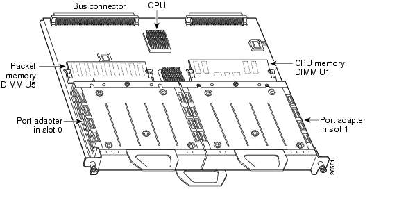
To upgrade CPU memory on your VIP4, you must replace the SDRAM DIMM located in socket U1. Be sure that you locate the correct socket, because you should not upgrade the SDRAM DIMM for packet memory that is located in socket U5. See Figure 4. The default memory configurations for the VIP4 are 64 MB of CPU memory and 64 MB of packet memory.
Note
Note
The following Cisco Systems memory spare and upgrade kits are compatible with the VIP4:
Depending on your system configuration, a memory upgrade might be required. Also, if a system problem is determined to be caused by a DIMM, a DIMM replacement might be required.
Figure 4 shows the locations of the CPU memory and packet memory SDRAM DIMMs on the VIP4.
Figure 4 Location of CPU Memory and Packet Memory DIMMs on the VIP4
Caution
Note
Removing SDRAM DIMMs
Use the following procedure to remove the existing DIMMs:
Step 1
Step 2
Position the VIP4 so that the handles are away from you and the bus connectors are toward you—opposite of the position shown in Figure 4.
Step 3
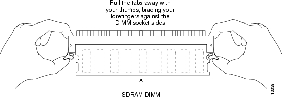
Step 4
Figure 5 Opening the DIMM Socket Tabs
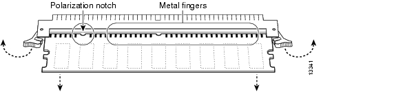
Step 5
Figure 6 Removing the DIMM
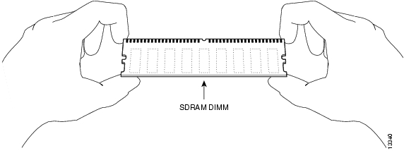
Note
Figure 7 Handling the DIMM
Caution
Step 6
This completes the DIMM removal procedure.
Installing SDRAM DIMMs
Caution
With the VIP4 in the same orientation as the previous procedure (with the handle away from you and the bus connector toward you), use the following procedure to install the new DIMM in the DIMM socket:
Step 1
Step 2
Note
Step 3
Caution
Step 4
Figure 8 Inserting the DIMM
Step 5
Step 6
This completes the DIMM replacement procedure. Reinstall the VIP4 in the system. (Follow the steps in the "Installing a VIP4" section.) See the following section, " Checking the VIP4 Memory Upgrade," as required.
Checking the VIP4 Memory Upgrade
After you upgrade the VIP4 memory, verify the memory upgrade:
•
•
If, after you have replaced memory devices, the system fails to boot properly, if the console terminal displays a checksum or memory error, or if the show diag command output indicates an incorrect amount of memory (or no memory), check the following:
•
•
•
If after several attempts the system fails to restart properly, contact a service representative for assistance. Before you call, make note of any error messages, unusual LED states, or any other indications that might help solve the problem.
This completes the VIP4 memory upgrade.
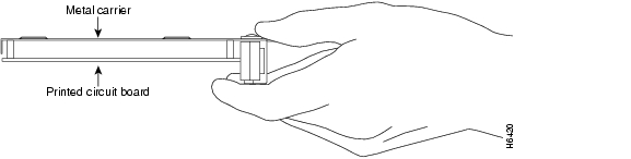
Always handle the port adapter by the carrier edges and handle; never touch the port adapter components or connector pins. (See Figure 9.)
Figure 9 Handling a Port Adapter
Caution
Warning
To replace a port adapter, use the procedure that is appropriate to your port adapter type:
•
•
Single-Width Port Adapter
Single-width port adapters occupy one of the two port adapter slots on a VIP4. When a single-width port adapter slot is not in use, a blank port adapter must fill the empty slot to allow the router to conform to electromagnetic interference (EMI) emissions requirements and to allow proper airflow through the router. If you plan to install a new single-width port adapter in a port adapter slot that is not in use, you must first remove the blank port adapter.
Figure 10 describes the steps required to install a single-width port adapter.
Figure 10 Removing and Installing a Single-Width Port Adapter
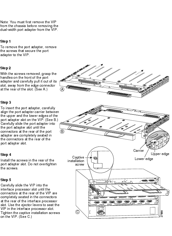
Dual-Width Port Adapter
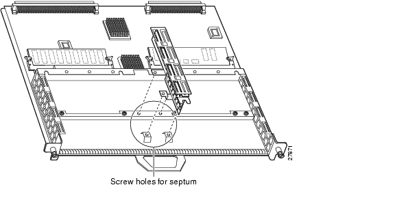
Dual-width port adapters occupy both port adapter slots on a VIP4. Before you can install a dual-width port adapter, you must first remove the slot divider that is located between the two port adapter slots. (See Figure 11.) Refer to Table 5 for a list of dual-width port adapters.
Figure 11 Location of VIP4 Slot Divider and Screws
Use the following procedure to remove the slot divider from a VIP4:
Step 1
Step 2
Step 3
Step 4
•
•
Step 5
Step 6
Note
With the slot divider removed, see Figure 12, which describes the steps required to install or remove a dual-width port adapter.
Figure 12 Removing and Installing a Dual-Width Port Adapter
VIP4 Troubleshooting
To troubleshoot the VIP4, refer to Troubleshooting VIP Crashes online at http://www.cisco.com/warp/customer/63/vip_crash.html which requires user registration to access. To become a registered user, refer to http://www.cisco.com/register/.
Listed below are common sense guidelines to troubleshoot the router, the VIP4 and its memory components, and the port adapter installation:
•
•
•
•
•
Obtaining Documentation
The following sections provide sources for obtaining documentation from Cisco Systems.
World Wide Web
You can access the most current Cisco documentation on the World Wide Web at the following sites:
•
•
•
Documentation CD-ROM
Cisco documentation and additional literature are available in a CD-ROM package, which ships with your product. The Documentation CD-ROM is updated monthly and may be more current than printed documentation. The CD-ROM package is available as a single unit or as an annual subscription.
Ordering Documentation
Cisco documentation is available in the following ways:
•
http://www.cisco.com/cgi-bin/order/order_root.pl
•
http://www.cisco.com/go/subscription
•
Documentation Feedback
If you are reading Cisco product documentation on the World Wide Web, you can submit technical comments electronically. Click Feedback in the toolbar and select Documentation. After you complete the form, click Submit to send it to Cisco.
You can e-mail your comments to bug-doc@cisco.com.
To submit your comments by mail, for your convenience many documents contain a response card behind the front cover. Otherwise, you can mail your comments to the following address:
Cisco Systems, Inc.
Document Resource Connection
170 West Tasman Drive
San Jose, CA 95134-9883We appreciate your comments.
Obtaining Technical Assistance
Cisco provides Cisco.com as a starting point for all technical assistance. Customers and partners can obtain documentation, troubleshooting tips, and sample configurations from online tools. For Cisco.com registered users, additional troubleshooting tools are available from the TAC website.
Cisco.com
Cisco.com is the foundation of a suite of interactive, networked services that provides immediate, open access to Cisco information and resources at anytime, from anywhere in the world. This highly integrated Internet application is a powerful, easy-to-use tool for doing business with Cisco.
Cisco.com provides a broad range of features and services to help customers and partners streamline business processes and improve productivity. Through Cisco.com, you can find information about Cisco and our networking solutions, services, and programs. In addition, you can resolve technical issues with online technical support, download and test software packages, and order Cisco learning materials and merchandise. Valuable online skill assessment, training, and certification programs are also available.
Customers and partners can self-register on Cisco.com to obtain additional personalized information and services. Registered users can order products, check on the status of an order, access technical support, and view benefits specific to their relationships with Cisco.
To access Cisco.com, go to the following website:
http://www.cisco.com
Technical Assistance Center
The Cisco TAC website is available to all customers who need technical assistance with a Cisco product or technology that is under warranty or covered by a maintenance contract.
Contacting TAC by Using the Cisco TAC Website
If you have a priority level 3 (P3) or priority level 4 (P4) problem, contact TAC by going to the TAC website:
http://www.cisco.com/tac
P3 and P4 level problems are defined as follows:
•
•
In each of the above cases, use the Cisco TAC website to quickly find answers to your questions.
To register for Cisco.com, go to the following website:
http://www.cisco.com/register/
If you cannot resolve your technical issue by using the TAC online resources, Cisco.com registered users can open a case online by using the TAC Case Open tool at the following website:
http://www.cisco.com/tac/caseopen
Contacting TAC by Telephone
If you have a priority level 1 (P1) or priority level 2 (P2) problem, contact TAC by telephone and immediately open a case. To obtain a directory of toll-free numbers for your country, go to the following website:
http://www.cisco.com/warp/public/687/Directory/DirTAC.shtml
P1 and P2 level problems are defined as follows:
•
•
This document is to be used in conjunction with the documents listed in the "Related Documentation" section section.
Copyright © 2002, Cisco Systems, Inc.
All rights reserved.
![]()
![]()
![]()
![]()
![]()
![]()
![]()
![]()
Posted: Wed Apr 12 16:11:36 PDT 2006
All contents are Copyright © 1992--2006 Cisco Systems, Inc. All rights reserved.
Important Notices and Privacy Statement.