|
|

Table Of Contents
Channelized T3 Interface Processor (CT3IP) Installation and Configuration
CT3IP Agency Compliance and Electrical Interface Specifications for T3 and T1
CT3IP Installation Prerequisites
Software and Hardware Prerequisites
Guidelines for Interface Processor Removal and Installation
Attaching Network Interface Cables to the CT3IP
Using LEDs to Check CT3IP Initialization
Using the EXEC Command Interpreter
Interface Port Numbering for T1 and T3
Port Numbering Examples and Sample Displays
Configuration Guidelines and Configuration Command Examples
Replacing and Upgrading CT3IP DRAM and SRAM
Checking DRAM and SRAM Replacement
Channelized T3 Interface Processor (CT3IP) Installation and Configuration
Product Numbers: CT3IP-20= and CT3IP-40(=)
Introduction
This configuration note contains instructions for installing the Channelized T3 Interface Processor (CT3IP) in the Cisco 7000 series routers and the Cisco 7500 series routers. For the CT3IP to operate properly in the Cisco 7000 series routers, the 7000 Series Route Switch Processor (RSP7000) and 7000 Series Chassis Interface (RSP7000CI) must be installed.
This configuration note also contains basic configuration steps and examples. For complete descriptions of additional interface subcommands and configuration options available for your router, refer to the appropriate configuration publications listed in the section " If You Need More Information" on page 2. (Also refer to the section " Software and Hardware Prerequisites" on page 8.)
Contents
Sections in this document include the following:
•
If You Need More Information, page 2
•
•
•
•
•
•
•
If You Need More Information
The Cisco IOS software running your router contains extensive features and functionality. For information on Cisco IOS software and for general installation and maintenance information for your router, use the following resources:
•
Cisco documentation and additional literature are available in a CD-ROM package, which ships with your product. The Documentation CD-ROM, a member of the Cisco Connection Family, is updated monthly; therefore, it might be more up to date than printed documentation. To order additional copies of the Documentation CD-ROM, contact your local sales representative or call customer service. The CD-ROM package is available as a single package or as an annual subscription.
•
•
•
Note
If you are reading Cisco documentation on the World Wide Web, you can submit comments electronically. Click Feedback on the toolbar, and then select Documentation. After you complete the form, click Submit to send it to Cisco. We appreciate your comments.•
•
•
•
What Is the CT3IP?
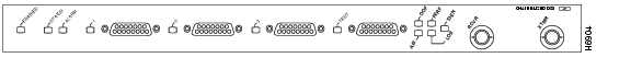
The CT3IP, shown in Figure 1 and , is a fixed-configuration interface processor based on the second-generation Versatile Interface Processor (VIP2).
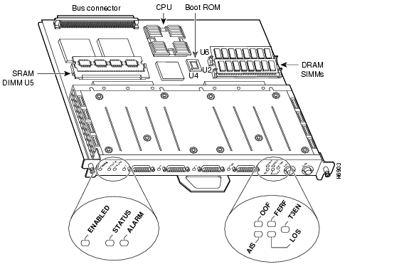
Figure 1 CT3IP, Front-Panel View
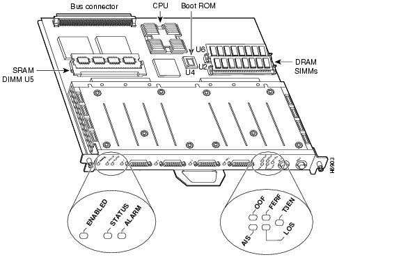
Figure 2 CT3IP, Top View
The CT3IP has the following features and physical characteristics:
•
•
•
•
•
•
•
•
T3 Overview
T3 traditionally involves multiplexing 28 T1 lines on to a single higher-speed line (T3 line). Each of the 28 T1 lines in the T3 are asynchronous to one other. A T1 line accommodates 24 64-kilobit-per-second (Kbps) DS0 channels. While the DS0s are byte multiplexed to each T1, the T1 lines are bit multiplexed to the T3 in a framing format called M23 or C-BIT parity.
M13 multiplexing is done in two steps. First, four T1 lines are bit multiplexed together to form a DS2 line using M12 multiplexing. These seven DS2 lines are then bit multiplexed together to form the DS3/T3 using M23 multiplexing.
M13 multiplexing uses bit stuffing to bring each asynchronous DS1/DS2 up to a common data rate for transmission. C-BIT Parity multiplexing forces the seven DS2s to be synchronous to each other at a rate that causes 100-percent pulse stuffing in the M23 frame. This allows the "stuff" indicator bits in the M23 frame to be used as a maintenance link between the end points.
CT3IP Overview
The CT3IP functions very much like an M13 multiplexer with each T1 line terminating with or originating into or from an HDLC controller on the port adapter. The CT3IP offers 28 individual T1 channels (bundled in the T3) for serial transmission of data. Each of the T1 channels uses a portion of the T1 bandwidth (fractional T1) or the entire T1 bandwidth for data transmission. Usable bandwidths for each T1 are n x 56 Kbps or n x 64 Kbps, where n is a number from 1 to 24. The unused portion of the T1 bandwidth, when not running at full T1 speeds, cannot be used and is filled with idle channel data.
Note
The T3 section of the CT3IP supports the maintenance data link channel (C-BIT parity) as well as payload and network loopbacks. The T1 section of the CT3IP supports Facility Data Link (FDL) in extended super frame (ESF) framing, as well as network and payload loopbacks. Bit error rate testing (BERT) is supported on each of the T1 links. The BERT testing is only done over a framed T1 signal. The M13 multiplexer performs M12 multiplexing on 4 four T1 signals. (There are seven M12 multiplexers available on board.) The seven M12 multiplexers pass their data to the M23 multiplexer, which takes the seven tributaries and formats them into a DS3 stream. This transmit stream is passed on to the T3 line interface unit (LIU) for transmission out of the BNC connector into a 75-ohm coaxial line.
The first three T1 channels of the channelized T3 can be broken out, under software control, to the three DB-15 connectors on the front of the CT3IP for further demultiplexing via a MultiChannel Interface Processor (MIP). This allows three (the first three) of the 28 T1 streams in the channelized T3 to be a channelized T1 stream.
The broken-out T1(s) are sent to a T1 LIU, which transmits the T1(s) at the DSX-1 level. (DSX-1 refers to the cross connection point for DS-1 signals.) When operating in this mode, these ports are not CSU ports. They do not detect loop codes, provide ones-density requirements, or respond to any FDL messages. The receiving end (MIP) must provide the CSU functionality. Under software control, each external T1 port can be disabled or enabled.
The CT3IP does not support the aggregation of multiple T1s (called inverse muxing or bonding) for higher bandwidth data rates. CT3IP supports Cisco HDLC, Frame Relay, PPP, and SMDS Data Exchange Interface (DXI) encapsulations over each T1 link. For SMDS only, DXI is sent on the T1 line so it needs to connect to an SMDS switch that has direct DXI input.
There is a special DB-15 connector on the CT3IP, labeled TEST. This test connector allows you to break out any T1 of the T3 stream, under software control. This functionality allows you to break out any of the 28 T1s within the T3 stream for testing (for example, 24-hour BERT testing as is commonly done by telephone companies before a line is brought into service), or for further channelization via a MIP card.
CT3IP Microcode
The CT3IP microcode is a software image that provides card-specific software instructions. Cisco 7000 series and Cisco 7500 series routers support downloadable microcode, which enables you to upgrade microcode versions by downloading new microcode images, storing them in Flash memory, and instructing the system to load an image from Flash memory.
You can store multiple images for an interface type and instruct the system to load any one of them with a configuration command. All interfaces of the same type (all CT3IPs, and so on) will load the same microcode image from a single image stored in Flash memory. The Flash-based boot read-only memory (ROM) device on the CT3IP contains a microcode boot image that instructs the system to load the full microcode image as described by the configuration.
Although multiple microcode versions for a specific interface type can be stored concurrently in Flash memory, only one image can load at startup. The show controller cbus command displays the currently loaded and running microcode version for each interface processor. The show microcode command displays the microcode images bundled with the Cisco IOS software.
An example follows:
Router# sh microcodeMicrocode bundled in systemCard Microcode Target Hardware DescriptionType Version Version---- --------- --------------- -----------(additional display text omitted)VIP2 21.40 2.x VIP2 version 21.40(additional display text omitted from this example)In the preceding example, the CT3IP's microcode is listed as VIP2 because the CT3 port adapter is attached to a VIP2 motherboard and uses its microcode image. For a complete description of microcode and downloading procedures, refer to the section " Upgrading Microcode" on page 41. The example does not necessarily show an actual version of CT3IP microcode.
CT3IP Cables
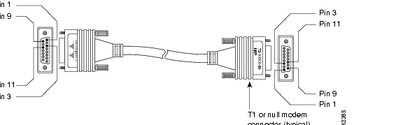
For T1, two standard serial cables, null-modem and straight-through, are available from Cisco Systems for use with the CT3IP. The CT3IP T1 interface cables are used to connect your router to external CSUs or a MIP card. The CT3IP T1 interface cables have two male 15-pin DB connectors at each end to connect the CT3IP's T1 interfaces.
Figure 3 shows the CT3IP interface cable, connectors, and pinouts. Table 1 lists the signal pinout for the straight-through cable. Table 2 lists the signal pinout for the null-modem cable.
Figure 3 CT3IP T1 Interface Cable and Connectors
Table 1 T1 Straight-Through Cable Signals
1
Tx tip
1
Tx tip
3
Rx tip
3
Rx tip
9
Tx ring
9
Tx ring
11
Rx ring
11
Rx ring
Case
Ground/shield
Case
Ground/shield
1 Tx = transmit. Rx = receive.
Table 2 T1 Null-Modem Cable Signals
1
Tx tip
3
Rx tip
3
Rx tip
1
Tx tip
9
Tx ring
11
Rx ring
11
Rx ring
9
Tx ring
Case
Ground/shield
Case
Ground/shield
1 Tx = transmit. Rx = receive.
CT3IP Agency Compliance and Electrical Interface Specifications for T3 and T1
The T3 line interface unit (LIU) is designed to meet the following specifications:
•
•
The T3 LIU is compliant for the above specifications for input jitter tolerance, pulse shape/amplitude (DSX3), line termination, and jitter. The LIU has a flat transfer function so jitter introduced by the LIU is insignificant.
The CT3IP T3 port is designed to receive and transmit at the DSX-3 level while driving and56 receiving from a 75-ohm coaxial cable (ATT 728A type coax). It connects directly to any equipment with DSX-3 level BNC connectors. The T3 front end is designed to meet the following specifications:
•
•
•
•
•
•
The T1 LIU is designed to meet the following specifications. (See also Table 3.)
•
•
The T1 LIU is designed to meet the preceding specifications for input jitter tolerance, pulse shape/amplitude (DSX1), line termination, and jitter. The LIU has a relatively flat transfer function so jitter introduced by the LIU is minimal.
The CT3IP T1 ports are designed to receive and transmit at the DSX-1 level while driving and receiving from a 100-ohm twisted-pair cable. It connects directly to any equipment with DSX-1 level input/output. The T1 front end is designed to meet the following specifications:
•
•
•
•
•
•
Table 3
1-20
n x 64 Kbps up to full T1 (1.536 Mbps)
21-28
n x 56 Kbps up to full T1 (1.344 Mbps)
or n x 64 Kbps up to full T1 (1.536 Mbps)
T1 Channel Data Rates
CT3IP Installation Prerequisites
Before you begin the installation, review the guidelines in this section to assure proper system operation, avoid injuring yourself, or damaging the equipment.
Software and Hardware Prerequisites
The CT3IP is compatible with any Cisco 7000 series or Cisco 7500 series router that is operating with Cisco IOS Release 11.1(8)CA or later; however, certain command and feature functionality is only available with Cisco IOS Release 11.1(9)CA1 or later, or Cisco IOS Release 11.2(7)P or later.
Note
For the CT3IP to operate properly in the Cisco 7000 series routers, the 7000 Series Route Switch Processor (RSP7000) and 7000 Series Chassis Interface (RSP7000CI) must be installed. The CT3IP will not operate properly in Cisco 7000 series routers with the Route Processor (RP) and Switch Processor (SP) (or Silicon Switch Processor [SSP]) installed.
The show version command displays the current hardware configuration of the router, including the system software version that is currently loaded and running. The show controller cbus command lists all electrical interfaces and includes the currently loaded and running microcode version for each.
If the displays indicate that the running system software is earlier than Cisco IOS Release 11.1(8)CA or later, check the contents of Flash memory to determine if the required images are available on your system. The show flash command displays a list of all files stored in Flash memory.
The show microcode command displays a list of all the microcode images currently bundled with the Cisco IOS software. If these displays indicate that the required system software and microcode are not available, contact a service representative for upgrade information. (Refer to the section " Upgrading Microcode," on page 41, for more information. For information on additional show commands, refer to the section " Command Descriptions and Examples" on page 28.)
Safety Guidelines
This section lists safety guidelines you should follow when working with any equipment that connects to electrical power or telephone wiring.
Electrical Equipment Guidelines
Follow these basic guidelines when working with any electrical equipment:
•
•
•
•
•
•
Telephone Wiring Guidelines
Use the following guidelines when working with any equipment that is connected to telephone wiring or to other network cabling:
•
•
•
•
Preventing Electrostatic Discharge Damage
Electrostatic discharge (ESD) damage, which can occur when electronic cards or components are improperly handled, results in complete or intermittent failures. The CT3IP comprises a printed circuit board that is fixed in a metal carrier. Electromagnetic interference (EMI) shielding, connectors, and a handle are integral components of the carrier. Although the metal carrier helps to protect the board from ESD, use a preventive antistatic strap whenever handling the CT3IP. Handle the carriers by the handles and the carrier edges only; never touch the boards or connector pins.
Following are guidelines for preventing ESD damage:
•
•
•
•
•
•
•
•
CautionFor safety, periodically check the resistance value of the antistatic strap. The measurement should be between 1 and 10 megohms.
Parts and Tools
You need the following tools and parts to install the CT3IP. If you need additional equipment, contact your service representative for ordering information.
•
•
•
•
•
•
•
Guidelines for Interface Processor Removal and Installation
This section describes mechanical functions of system components, emphasizes the importance of following correct procedures to avoid unnecessary board failures, and is for background only; specific procedures follow in the section " CT3IP Installation Procedures" on page 14.
You can remove and replace interface processors while the system is operating; you do not need to notify the software or reset the system power. This functionality enables you to add, remove, or replace interface processors with the system online, which provides a method that is seamless to end users on the network, maintains all routing information, and ensures session preservation.
After an interface processor is reinstalled, the system brings on line only interfaces that match the current configuration and were previously configured as up; all others require that you configure them with the configure command.
CautionThe system can indicate a hardware failure if you do not follow proper procedures. Remove or insert only one interface processor at a time. Allow at least 15 seconds for the system to complete the preceding tasks before removing or inserting another interface processor. Disrupting the sequence before the system completes its verification can cause the system to interpret hardware failures.
All interface processors have ejector levers that allow you to firmly seat an interface processor in the interface processor slot. The function of the ejector levers is to align and seat the card connectors in the backplane. Failure to use the ejector levers and insert the interface processor properly can disrupt the order in which the pins make contact with the backplane.
Follow the installation and removal instructions carefully, and review the following examples of incorrect insertion practices and results:
•
•
•
•
•
It is also important to use the ejector levers when removing an interface processor to ensure that the board connector pins disconnect from the backplane in the logical sequence expected by the system. Any processor module that is only partially connected to the backplane can hang the bus. Detailed steps for correctly installing and removing the interface processor follow.
The processor modules slide into slots in the rear of the chassis and connect directly to the backplane. The backplane slots are keyed so that the processor modules can be installed only in the slots designated for them.
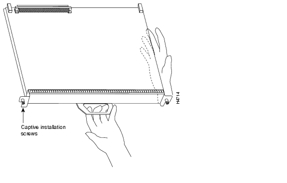
shows the ejector levers and captive installation screws on a typical interface processor. To remove an interface processor, loosen the captive screws and pull the ejector levers to the sides; then pull the module out using the handle. To insert an interface processor, reverse the process, making sure to firmly seat the interface processor in its connectors on the backplane. For detailed directions, follow the procedures in the section " CT3IP Installation Procedures" on page 14.
CautionAlways use the ejector levers to remove or install the CT3IP. The ejectors help ensure that backplane connectors on the card are fully seated in, or fully ejected from, the backplane. Failure to use the ejector levers could result in a partial backplane connection, which can hang the system.
The captive installation screws on the ends (see ) of each faceplate, when tightened, provide EMI shielding and also help ensure proper seating in the backplane. After using the ejector levers to install a CT3IP, tighten the captive installation screws to prevent the CT3IP from becoming partially dislodged from the backplane. These screws must be tightened to meet EMI specifications.
Figure 4 Ejector Levers and Captive Installation Screws
(Horizontal Orientation Shown)
CT3IP Installation Procedures
The following sections describe the procedures for removing or installing the CT3IP. The OIR feature allows you to install and remove the CT3IP without turning off system power. Refer to the section " Guidelines for Interface Processor Removal and Installation," on page 11, for a complete description of OIR.
CautionTo avoid erroneous failure messages, remove or insert only one interface processor at a time. Also, after inserting or removing an interface processor, allow at least 15 seconds before removing or inserting another interface processor so that the system can reinitialize and note the current configuration of all interfaces. For the initial release of the CT3IP, OIR for the CT3IP functions as described; however, if you install or remove other interface processors in a Cisco 7000 series or Cisco 7500 series router with a CT3IP installed, you might have to reset the chassis after OIR of that interface processor. To prevent system problems, we recommend you follow the OIR procedures.
Removing a CT3IP
You need not shut down the interface or the system power when removing a CT3IP or other interface processor.
Note
If you have a Cisco 7507 or a Cisco 7513 with an RSP2 configured as the system slave, we strongly recommend that you use the following procedure to remove and replace an interface processor:
Step 1
Step 2
Step 3
Step 4
Step 5
If you are replacing a failed CT3IP, remove the existing board first, then replace the new CT3IP in the same slot. If you are replacing a currently installed interface processor with a CT3IP, remove the existing board first, then install the new CT3IP in the same slot.
Figure 5 shows proper handling of an interface processor during installation.
Figure 5 Handling Interface Processors during Installation
(Horizontal Orientation Shown)
To remove the CT3IP, follow these steps:
Step 1
Step 2
CautionAlways use the ejector levers to remove or install the CT3IP. Failure to do so can cause erroneous system error messages, indicating a board failure.
Step 3
Step 4
Step 5
Step 6
Step 7
(MAS-7000BLANK=) to keep dust out of the chassis and to maintain proper airflow through the interface processor compartment.Installing a CT3IP
The CT3IP slides into any available interface processor slot and connects directly to the backplane. The backplane slots are keyed so that the CT3IP can be installed only in an interface processor slot. Interface processor fillers, which are blank interface processor carriers, occupy empty slots to maintain consistent air flow through the interface processor compartment. If you are installing a new CT3IP, you will have to first remove the interface processor filler from the available interface processor slot. Figure 4 shows the functional details of inserting an interface processor and using the ejector levers. Figure 5 shows proper handling of an interface processor during installation.
Note
CautionRemove or insert only one interface processor at a time. Allow at least 15 seconds for the system to complete the preceding tasks before removing or inserting another interface processor. Disrupting the sequence before the system completes its verification can cause the system to interpret hardware failures.
Follow these steps to install the CT3IP:
Step 1
Step 2
Step 3
Step 4
CautionTo prevent ESD damage, handle interface processors by the handles and carrier edges only.
Step 5
Step 6
CautionAlways use the ejector levers when installing or removing processor modules. A module that is partially seated in the backplane will cause the system to hang and subsequently crash.
Step 7
Step 8
CautionAlways tighten the captive installation screws on interface processors. These screws prevent accidental removal and provide proper grounding for the system.
This completes the CT3IP installation. Proceed to the following section to attach interface cables to the CT3IP.
Attaching Network Interface Cables to the CT3IP
Attach the CT3IP network interface cables between the CT3IP interface ports and the CSU. This includes up to four T1 cables and two DS1 BNC cables. (See Figure 6.) Proceed to the following section to check the cable connections.
Figure 6 Connecting Interface Cables to the CT3IP (Horizontal Orientation Shown)
Using LEDs to Check CT3IP Initialization
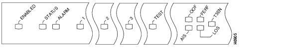
The CT3IP has several status LEDs on its faceplate. (See Figure 7.)
Figure 7 CT3IP LEDs (Horizontal Orientation Shown)
Following are the functions of the CT3IP LEDs:
•
•
For additional functions of the status and alarm LEDS, refer to the section " Using Status and Alarm LED Indications" on page 37.
The individual 1, 2, 3, and test LEDS next to each T1 port indicate the following: This green LED will go on when the respective port is enabled. When the port is not enabled, the LED is off.
The remaining five LEDs, between the TEST and T3 ports, indicate the following:
•
•
•
•
•
Note
Observe the LED states and the console displays as the router initializes. When the system has reinitialized all interfaces, the enabled LED on the CT3IP should go on.
The console screen will also display a message as the system discovers each interface during its reinitialization. After system initialization, the enabled LED goes on to indicate that the CT3IP is enabled for operation.
The following conditions must be met before the CT3IP is enabled:
•
•
•
If any of these conditions is not met, the enabled LED does not go on.
Verify that the CT3IP is connected correctly as follows:
Step 1
Step 2
Step 3
Step 4
•
•
•
•
Step 5
If an error message displays on the console terminal, refer to the appropriate reference publication for error message definitions. If you experience other problems that you are unable to solve, contact a service representative for assistance.
Configuring the CT3IP
If you installed a new CT3IP or if you want to change the configuration of an existing controller, you must enter the Configuration mode. If you replaced the CT3IP that was previously configured, the system will recognize the new CT3IP and bring it up in the existing configuration.
After you verify that the new CT3IP is installed correctly, use the privileged-level configure command to configure the new CT3IP controller. Be prepared with the information you will need, such as the following:
•
•
•
•
•
•
For a complete summary of the configuration options available and more detailed instructions for configuring the CT3IP controller, refer to the appropriate configuration publications, which are listed in the section " If You Need More Information," on page 2.
Using the EXEC Command Interpreter
Before you can use the configure command, you must enter the privileged level of the EXEC command interpreter with the enable command. The system will prompt you for a password if one has been set.
The system prompt for the privileged level ends with a pound sign (#) instead of an angle bracket (>). At the console terminal, enter the privileged level as follows:
Step 1
Router> enablePassword:Step 2
Step 3
Router#
Note
Proceed to the following section to configure the CT3IP controller.
Interface Port Numbering for T1 and T3
The interface numbering scheme for the CT3IP's T1 interfaces is in the form of slot/port-adapter/port:t1 channel: where slot refers to the chassis slot in which the CT3IP is installed, port-adapter is always 0 (because the CT3IP has only one dual-width port adapter); port refers to the physical port on the CT3IP and is always 0; and t1 channel is a number between 1 and 28. (Refer to the section " Configuring the CT3IP," on page 20, for more specific interface configuration information.)
Note
Designate and turn on an external T1 port (one of the three DB-15 connectors labeled 1 through 3) using the t1 external channel command, where t1 channel is a number between 1 and 3.
Designate and turn on the T1 test port (the DB-15 connector labeled TEST) using the t1 test channel command, where t1 channel is a number between 1 and 28.
Port Numbering Examples and Sample Displays
Following are examples of CT3IP interface port numbering and sample displays:
•
•
The following sample display shows the events logged by the system as the CT3IP was removed from slot 3; the system then reinitialized the remaining interface processors and marked as down the CT3IP when it is installed in slot 4. When the CT3IP was reinserted, the system marked the interfaces as down again because the CT3IP interfaces were not shut down before the CT3IP was removed.
Router#%OIR-6-REMCARD: Card removed from slot 3, interfaces disabled%LINK-5-CHANGED: Interfaces T3 3/0/0, changed to administratively downWhen a new CT3IP is inserted, or when a CT3IP whose interfaces are shut down is moved to a new slot, the system recognizes the CT3IP controller, but leaves its interfaces in a shutdown state until you configure them and change the state to up with the configure command. If you move a CT3IP to a new slot and its interfaces were not shut down, the system recognizes them as not shut down when the CT3IP is installed in the new slot.
The following example display shows the events logged by the system as a new CT3IP is inserted in slot 4:
Router#%OIR-6-INSCARD: Card inserted in slot 4, interfaces administratively shut down%LINK-5-CHANGED: Interfaces T3 4/0/0, changed to administratively downRouter#Configuration Guidelines and Configuration Command Examples
The following steps describe basic configuration guidelines and configuration command examples for the T3 and then T1 interfaces. Press the Return key after each step.
Configuring the T3 Interface
Following are the steps to configure the T3 interface:
Step 1
Router# conf t Enter configuration commands, one per line. End with CNTL/Z.Router(config)#Step 2
Router(config)# cont t3 3/0/0Step 3
Router(config-controll)# framing c-bitAt the prompt, request the CT3IP to detect the framing type it is to receive from the far end, as follows:
Router(config-controll)# framing auto-detectStep 4
Router(config-controller)# cablelength 200
Note
In the preceding example, a cable length of 200 is specified. If it is changed to 220, then the 0-224 range applies in each case. Further, if a cable length of 300 is specified, then is changed to 400, the 225-450 range applies in each case; therefore, these changes have no effect. Only moving from one range to another has an effect. The actual number you enter is stored in the configuration file.Step 5
Router(config-controll)# clock source line
Note
Configuring MDL Messages
Maintenance Data Link (MDL) messages (which are defined in the ANSI T1.107a-1990 specification) can be configured on the CT3IP.
Note
To configure MDL messages, use the following controller configuration commands:
mdl {transmit {path | idle-signal | test-signal} | string {eic | lic | fic | unit | pfi | port | generator} string}
no mdl {transmit {path | idle-signal | test-signal} | string {eic | lic | fic | unit | pfi | port | generator} string}where the command arguments are defined as follows:
•
•
•
•
•
•
•
Use the no form of this command to remove message. The default is that no MDL message is configured.
Examples of MDL Message Configuration
Following are examples of configuring MDL messages; enter controller Configuration mode first, as follows:
Router# conf t
Enter configuration commands, one per line. End with CNTL/Z.
Router(config)# cont t3 3/0/0Router(config-controll)#•
Router(config-controll)# mdl string eic router A•
Router(config-controll)# mdl string lic test network•
Router(config-controll)# mdl string fic buidling b•
Router(config-controll)# mdl string unit abc•
Router(config-controll)# mdl string pfi string•
Router(config-controll)# mdl string port string•
Router(config-controll)# mdl string generator string•
Router(config-controll)# mdl transmit path•
Router(config-controll)# mdl transmit idle-signal•
Router(config-controll)# mdl transmit test-signalConfiguring the Logical T1 Interfaces
Following are the guidelines for configuring the logical T1 interfaces using controller configuration commands. Examples follow:
Step 1
Where T1 channels are 1-28, range supports contiguous timeslots as well as arbitrary timeslots, and a speed of 56 Kbps is only valid for T1 21-28 (default is 64 Kbps).
Examples follow:
Configure T1 0 for full T1 bandwidth, as follows:
Router(config-controll)# t1 0 timeslots 1-24 speed 64Configure the T1 20 to use timeslots 1 through 5 and timeslots 20 through 23 as follows:
Router(config-controll)# t1 20 timeslots 1-5,20-23Configure the T1 21 for 24 x 56 Kbps as follows:
Router(config-controll)# t1 21 timeslot 1-24 speed 56Step 2
Examples follow:
Set super frame (SF) framing format for T1 6 as follows:
Router(config-controll)# t1 6 framing sf
Note
Set ESF framing format for T1 18 as follows:
Router(config-controll)# t1 18 framing esfStep 3
An example follows:
Router(config-controller)# t1 0 linecode amiRouter(config-controller)# int s2/0/0:0Router(config-if)# invert data
Note
When the argument b8zs is selected, the pulse density enforcer will be disabled. When the ami argument is selected, the pulse density enforcer will be enabled. To avoid having the pulse density enforcer corrupt data, the T1 interface should be configured for inverted data, as described above, when the ami argument is selected.Step 4
Examples follow:
Set internal clock source for T1 6 as follows:
Router(config-controll)# t1 6 clock source internalSet network clock source for T1 1 as follows:
Router(config-controll)# t1 1 clock source lineTo remove a T1 channel, use the no t1 t1 channel timeslots 1-24 command, where the T1 channel is 1-28. For example, remove the channel for T1 20 as follows:
Router(config-controll)# no t1 20 timeslots 1-24
Note
Configuring the External T1 Ports on a CT3IP
The following controller configuration commands are valid only to the first three T1 channels (T1 0 through 2) when they are broken out to the external T1 port. Configure a T1 Interface as an external port using the t1 external t1 channel [linecode {b8zs | ami}] [cablelength feet] command, where external T1 channels are 1-3, and the cable length range is 0-655 feet. The default values are as follows: line code is B8ZS; cable length is 133 feet.
(Use the show controller t3 command to check the status of the external ports; refer to the example of this command on page 31 of the section " Command Descriptions and Examples.")
For example, configure T1 1 to be an external port as follows:
Router(config-controll)# t1 external 1 lincecode ami cablelength 300To remove a T1 interface from an external port, use the no t1 external t1 channel command, where external T1 channels are 1-3.
For example, remove T1 1 from external port 1 as follows:
Router(config-controll)# no t1 external 1
Note
Configuring the T1 Test Port on a CT3IP
The following controller configuration commands are valid only to the T1 test port. Configure the T1 test port using the t1 test t1 test channel [linecode {b8zs | ami}] [cablelength feet] command, where the T1 test channels are 1-28, and the cable length range is 0-655 feet. The default values are as follows: line code is B8ZS; cable length is 133 feet.
(Use the show controller t3 command to check the status of the test port; refer to the example of this command on page 31 of the section " Command Descriptions and Examples.")
For example, bring T1 20 to the test port as follows:
Router(config-controll)# t1 test 20 lincecode ami cablelength 300
Note
In the preceding example, a cable length of 300 is specified. If it is changed to 350, then the 267-399 range applies in each case. Further, if a cable length of 550 is specified, then is changed to 600, the 534-655 range applies in each case; therefore, in each example, these changes have no effect. Only moving from one range to another has an effect. The actual number you enter is stored in the configuration file.To remove a T1 port from the test port, use the no t1 test t1 test channel command, where T1 test channels are 1-28.
For example, remove T1 20 from the test port as follows:
Router(config-controll)# no t1 test 20
Note
Additional Commands for CT3IP Configuration
Following are additional commands required to complete the CT3IP configuration:
Step 1
Router(config-if)# ip address 1.1.15.1 255.255.255.0Router(config-if)#Step 2
Step 3
Step 4
Router# copy running-config startup-config[OK]Router#The system displays an OK message when the configuration is stored.
Step 5
Router# disableRouter>Proceed to the following section to check the interface configuration with show commands.
Checking the Configuration
After configuring the new interface, use the show commands to display the status of the new interface or all interfaces. Using the show controller T3 slot/port-adapter/port:t1 channel command, display T3 or T1 channel information as follows, where the T1 channel is 1-28:
•
Router# show controller t3 3/0/0•
Router# show controller t3 3/0/0:5•
Router# show controller t3 3/0/0 briefCommand Descriptions and Examples
Following are descriptions and examples of the show commands. Descriptions are limited to fields that are relevant for verifying the configuration.
•
Following is an example from a Cisco 7505 router:
Router# show versionCopyright (c) 1986-1996 by cisco Systems, Inc.Compiled Tue 09-Jul-96 09:58 by biffImage text-base: 0x600108A0, data-base: 0x606C6000ROM: System Bootstrap, Version 5.3.2(3.2) [kmac 3.2], RELEASED SOFTWAREROM: GS Software (RSP-P-M), Version 11.1(9)CA1, RELEASED SOFTWARERouter uptime is 19 hours, 15 minutesSystem restarted by reloadSystem image file is "rsp-pv-mz", booted via tftp from 1.1.1.254cisco RSP1 (R4600) processor with 16384K bytes of memory.R4600 processor, Implementation 32, Revision 2.0Last reset from power-onG.703/E1 software, Version 1.0.X.25 software, Version 2.0, NET2, BFE and GOSIP compliant.Chassis Interface.1 VIP2 controller.1 Channelized T3 port.125K bytes of non-volatile configuration memory.8192K bytes of Flash PCMCIA card at slot 0 (Sector size 128K).8192K bytes of Flash internal SIMM (Sector size 256K).Configuration register is 0x0•
Router# show cont cbusslot3: VIP2, hw 2.4, sw 21.40, ccb 5800FF40, cmdq 48000090, vps 8192software loaded from systemIOS (tm) VIP Software (SVIP-DW-M), Version 11.1(9)CA1 [biff 120]ROM Monitor version 17.0CT3 H/W Version : 4, CT3 ROM Version : 0.116, CT3 F/W Version : 0.7.0Mxt H/W version : 2, Mxt ucode ver : 1.24T3 2/0/0, applique is Channelized T3gfreeq 48000138, lfreeq 48000168 (1536 bytes), throttled 0rxlo 4, rxhi 258, rxcurr 4, maxrxcurr 130Router#
Note
•
Router# show cont t3 3/0/0T3 3/0/0 is up.Applique type is Channelized T3No alarms detected.Framing is C-BIT Parity, Line Code is B3ZS, Clock Source is Line.Data in current interval (120 seconds elapsed):1 Line Code Violations, 2 P-bit Coding Violation3 C-bit Coding Violation4 P-bit Err Secs, 5 P-bit Severely Err Secs6 Severely Err Framing Secs, 7 Unavailable Secs8 Line Errored Secs, 9 C-bit Errored Secs, 10 C-bit Severely Errored SecsData in Interval 1:10 Line Code Violations, 12 P-bit Coding Violation0 C-bit Coding Violation14 P-bit Err Secs, 15 P-bit Severely Err Secs16 Severely Err Framing Secs, 17 Unavailable Secs18 Line Errored Secs, 19 C-bit Errored Secs, 20 C-bit Severely Errored SecsData in Interval 2:10 Line Code Violations, 12 P-bit Coding Violation0 C-bit Coding Violation14 P-bit Err Secs, 15 P-bit Severely Err Secs16 Severely Err Framing Secs, 17 Unavailable Secs18 Line Errored Secs, 19 C-bit Errored Secs, 20 C-bit Severely Errored SecsData in Interval 3:10 Line Code Violations, 12 P-bit Coding Violation0 C-bit Coding Violation14 P-bit Err Secs, 15 P-bit Severely Err Secs16 Severely Err Framing Secs, 17 Unavailable Secs18 Line Errored Secs, 19 C-bit Errored Secs, 20 C-bit Severely Errored SecsT1 0, speed: 1536 kbstimeslots: 1-24No alarms detected.Framing is ESF, LineCode is AMI, Clock Source is Line.Data in current interval (180 seconds elapsed):2 Line Code Violations, 1 Path Code Violations7 Slip Secs, 5 Fr Loss Secs, 8 Line Err Secs, 10 Degraded Mins3 Errored Secs, 9 Bursty Err Secs, 4 Severely Err Secs, 6 Unavail SecsData in Interval 1:12 Line Code Violations, 11 Path Code Violations17 Slip Secs, 15 Fr Loss Secs, 18 Line Err Secs, 20 Degraded Mins13 Errored Secs, 19 Bursty Err Secs, 14 Severely Err Secs, 16 Unavail SecsData in Interval 2:12 Line Code Violations, 11 Path Code Violations17 Slip Secs, 15 Fr Loss Secs, 18 Line Err Secs, 20 Degraded Mins13 Errored Secs, 19 Bursty Err Secs, 14 Severely Err Secs, 16 Unavail SecsData in Interval 3:12 Line Code Violations, 11 Path Code Violations17 Slip Secs, 15 Fr Loss Secs, 18 Line Err Secs, 20 Degraded Mins13 Errored Secs, 19 Bursty Err Secs, 14 Severely Err Secs, 16 Unavail SecsT1 1, speed: 1536 kbstimeslots: 1-24No alarms detected.Framing is ESF, LineCode is AMI, Clock Source is Line.Data in current interval (250 seconds elapsed):2 Line Code Violations, 1 Path Code Violations7 Slip Secs, 5 Fr Loss Secs, 8 Line Err Secs, 10 Degraded Mins3 Errored Secs, 9 Bursty Err Secs, 4 Severely Err Secs, 6 Unavail SecsData in Interval 1:12 Line Code Violations, 11 Path Code Violations17 Slip Secs, 15 Fr Loss Secs, 18 Line Err Secs, 20 Degraded Mins13 Errored Secs, 19 Bursty Err Secs, 14 Severely Err Secs, 16 Unavail SecsData in Interval 2:12 Line Code Violations, 11 Path Code Violations17 Slip Secs, 15 Fr Loss Secs, 18 Line Err Secs, 20 Degraded Mins13 Errored Secs, 19 Bursty Err Secs, 14 Severely Err Secs, 16 Unavail SecsData in Interval 3:12 Line Code Violations, 11 Path Code Violations17 Slip Secs, 15 Fr Loss Secs, 18 Line Err Secs, 20 Degraded Mins13 Errored Secs, 19 Bursty Err Secs, 14 Severely Err Secs, 16 Unavail SecsRouter#•
Router# show cont t3(additional displayed text omitted from this example)Ext1: LOS, Ext2: LOS, Ext3: LOS, Test: OKThe information in the preceding example is displayed even if the external or test ports are not configured, which allows you to determine the health of the external equipment and cabling before configuring the external or test ports.
Following are explanations of the individual fields in this line:
•
•
•
•
Router# show controller t3 2/0/0 briefT3 2/0/0 is up.CT3 H/W Version : 4, CT3 ROM Version : 0.116, CT3 F/W Version : 0.7.0Mxt H/W version : 2, Mxt ucode ver : 1.24Applique type is Channelized T3No alarms detected.FEAC code received : No code is being receivedFraming is C-BIT Parity, Line Code is B3ZS, Clock Source is Internal.T1 0 is up, speed: 1536 kbs, non-inverted datatimeslots: 1-24No alarms detected.Framing is ESF, LineCode is B8ZS, Clock Source is Internal.T1 1 is up, speed: 1536 kbs, non-inverted datatimeslots: 1-24No alarms detected.Framing is ESF, LineCode is B8ZS, Clock Source is Internal.T1 2 is up, speed: 1536 kbs, non-inverted datatimeslots: 1-24No alarms detected.Framing is ESF, LineCode is B8ZS, Clock Source is Internal.•
An example follows:
Router# sh cont t3 2/0/0:1 briefT3 2/0/0 is up.CT3 H/W Version : 4, CT3 ROM Version : 0.116, CT3 F/W Version : 0.7.0Mxt H/W version : 2, Mxt ucode ver : 1.24Applique type is Channelized T3No alarms detected.FEAC code received : No code is being receivedFraming is C-BIT Parity, Line Code is B3ZS, Clock Source is Internal.T1 1 is up, speed: 1536 kbs, non-inverted datatimeslots: 1-24No alarms detected.Framing is ESF, LineCode is B8ZS, Clock Source is Internal.•
Router# show protocolsSerial3/0/0:0 is up, line protocol is upInternet address is 30.30.30.2/24Serial3/0/0:1 is up, line protocol is upInternet address is 1.1.1.2/24•
Router# show startup-configcontroller T3 3/0/0cablelength 224t1 0 timeslots 1-24t1 1 timeslots 1-24t1 2 timeslots 1-24!interface Serial3/0/0:0ip address 30.30.30.2 255.255.255.0no ip route-cache optimumno keepaliveno fair-queue!interface Serial3/0/0:1ip address 1.1.1.2 255.255.255.0no ip route-cache optimumno keepaliveno fair-queue!interface Serial3/0/0:2ip address 2.2.2.2 255.255.255.0no ip route-cache optimumno keepaliveno fair-queue!(additional display text omitted from this example)•
Router# sh int serial 3/0/0:0Serial3/0/0:0 is up, line protocol is upHardware is cxBus T3Internet address is 30.30.30.2/24MTU 1500 bytes, BW 1536 Kbit, DLY 20000 usec, rely 255/255, load 1/255Encapsulation HDLC, loopback not set, keepalive not setLast input 10:05:52, output 10:05:52, output hang neverLast clearing of "show interface" counters 17:53:35Queueing strategy: fifoOutput queue 0/40, 0 drops; input queue 0/75, 26 drops5 minute input rate 1426000 bits/sec, 1700 packets/sec5 minute output rate 0 bits/sec, 0 packets/sec102606572 packets input, 2285893928 bytes, 1 no bufferReceived 0 broadcasts, 0 runts, 0 giants298 input errors, 0 CRC, 0 frame, 298 overrun, 0 ignored, 0 abort5 packets output, 530 bytes, 0 underruns0 output errors, 0 collisions, 0 interface resets0 output buffer failures, 0 output buffers swapped out0 carrier transitions no alarm presentTimeslot(s) Used:1-24, Transmitter delay is 0 flags, transmit queue length 7 non-inverted dataUsing Show Commands to Verify the CT3IP Status
The following procedure summarizes how to use the show commands to verify that a new CT3IP interface is configured correctly:
Step 1
Step 2
Step 3
Step 4
Step 5
Step 6
If the interface is down and you configured it as up, or if the displays indicate that the hardware is not functioning properly, ensure that the network interface is properly connected and terminated. If you still have problems bringing the interface up, contact a customer service representative for assistance.
This completes the configuration procedure for the new CT3IP interface.
Testing and Troubleshooting the CT3IP Using loopback Commands, LED Indications, and a BERT
Following are suggested guidelines for troubleshooting the CT3IP using the loopback command, LED indications, a bit error rate test (BERT), FDL performance reports, and for displaying remote performance reports.
Using loopback Commands
Should you have difficulty with the CT3IP configuration or installation, you can troubleshoot the CT3IP using the loopback interface configuration command. Specify loopback for a T1 channel where the T1 channel is 1-28. Specify the loopback format using the following command format:
loopback [local | network {line | payload} | remote {line {fdl {ansi | bellcore} |
inband}
payload [fdl] [ansi]}]
Use the no form of this command to remove the loopback.
Note
Explanations of specific loopback modes follow:
Examples of using the loopback command follow:
•
Router# config tEnter configuration commands, one per line. End with CNTL/Z.Router(config)# interface serial 2/0/0:1Router(config)# loopback localIn the preceding example, local loopback loops the router output data back toward the router at the T1 framer and sends an AIS signal out toward the network.
•
Router# config tEnter configuration commands, one per line. End with CNTL/Z.Router(config)# interface serial 2/0/0:1Router(config)# loopback network lineIn the preceding example, network line loopback loops the data back toward the network (before the T1 framer).
•
Router# config tEnter configuration commands, one per line. End with CNTL/Z.Router(config)# interface serial 2/0/0:1Router(config)# loopback network payloadIn the preceding example, network payload loopback loops just the payload data back toward the network at the T1 framer.
•
Router# config tEnter configuration commands, one per line. End with CNTL/Z.Router(config)# int serial 2/0/0:1Router(config-if)# loop remote line fdl ansiIn the preceding example, a repeating 16-bit ESF data link code word (of 00001110 11111111) is sent to the remote end requesting that it enter into a network line loopback. The ansi keyword enables the remote line Facility Data Link (FDL) ANSI bit loopback on the T1 channel, per the ANSI T1.403 Specification
•
Router# config tEnter configuration commands, one per line. End with CNTL/Z.Router(config)# int serial 2/0/0:1Router(config-if)# loop remote line fdl bellcoreIn the preceding example, a repeating 16-bit ESF data link code word (of 00010010 11111111) to the remote end requesting that it enter into a network line loopback. The bellcore keyword enables the remote SmartJack loopback on the T1 channel, per the TR-TSY-000312 Specification.
•
Router# config tEnter configuration commands, one per line. End with CNTL/Z.Router(config)# int serial 2/0/0:1Router(config-if)# loop remote line inbandIn the preceding example, remote line inband loopback sends a repeating 5-bit inband pattern (of 00001) to the remote end requesting that it enter into a network line loopback.
•
Router# config tEnter configuration commands, one per line. End with CNTL/Z.Router(config)# int serial 2/0/0:1Router(config-if)# loop remote payload fdl ansiIn the preceding example, remote payload ANSI bit loopback sends a repeating 16-bit ESF data link code word (of 00010100 11111111) to the remote end requesting that it enter into a network payload loopback.
To better diagnose T1 provisioning problems, you can place the remote CSU or remote SmartJack into loopback. The loopback remote line fdl interface configuration command allows you to place either the CSU or the SmartJack into loopback:
•
•
When both are configured, transmission of LOF indication (yellow alarm) takes priority over transmission of some FDL messages.
If the remote loopback appears not to be working, use the show cont t3 command to determine if the given T1 is currently attempting to transmit a LOF indication (yellow alarm):
Router# show controllers t3 2/0/0:2T3 2/0/0 is up.CT3 H/W Version: 5, CT3 ROM Version: 1.2, CT3 F/W Version: 2.5.9Mx H/W version: 2, Mx ucode ver: 1.34T1 2 is down, speed: 1536 kbs, non-inverted datatimeslots: 1-24FDL per AT&T 54016 spec.Transmitter is sending LOF Indication.Receiver is getting AIS.If the transmitter is sending a LOF indication, as in the previous example, stop the transmission of the LOF indication (yellow alarm) with the no t1 yellow generation configuration command as shown in the following example:
Router(config)# controllers t3 2/0/0Router(config-controll)# no t1 2 yellow generationRouter(config-controll)# ^DTo verify that the transmission of the LOF indication (yellow alarm) has stopped, use the show cont t3 command:
Router# show cont t3 2/0/0:2T3 0/0/0 is up.CT3 H/W Version: 5, CT3 ROM Version: 1.2, CT3 F/W Version: 2.5.9Mx H/W version: 2, Mx ucode ver: 1.34T1 2 is down, speed: 1536 kbs, non-inverted datatimeslots: 1-24FDL per AT&T 54016 spec.Receiver is getting AIS.Framing is ESF, Line Code is B8ZS, Clock Source is Internal.Yellow Alarm Generation is disabledNow retry the remote loopback command. When diagnosis is complete, remember to re-enable the LOF indication (yellow alarm). You can also loopback all the T1 channels by using the loopback (CT3IP) interface configuration command.
Using Status and Alarm LED Indications
Following are various system states and functions that are reflected by the front-panel alarm and status LEDs on the CT3IP during the CPU boot process and microcode download.
1
2
3
Note
During the system bootup process and microcode download, the following LED error indications might appear:
•
•
•
•
In all the preceding error modes, the CPU continually loops and the system does not proceed to the microcode download.
Checking Bit Errors Using a BERT
To check bit errors using a bit error test (BERT), use the following command:
[no] t1 t1 channel bert pattern {2^15 | 2^20 | 2^23 | 0s | 1s} interval minuteswhere t1 channel is 1-28, 2^15 is an exponential number that represents a pseudo-random repeating pattern that is 32767 bits long, 2^20 is a pseudo-random repeating pattern that is 1048575 bits long, 2^23 is a pseudo-random repeating pattern that is 8388607 bits long, 0s is a pattern of all zeroes (00000000...), 1s is a pattern of all 1s (111111...), and minutes are 1-14400, which designate the time the BERT will run. To stop the BERT, use the optional no form of the command. Following is an example of this command, where the pseudo-random pattern 2^20 is sent and repeats on the first T1 channel for 60 minutes:
Router# t1 1 bert pattern 2^20 interval 60Note that the BERT command is not saved in NVRAM. The test patterns from the CT3IP are framed test patterns; therefore, they are inserted into the payload of a framed T1 signal.
To display the BERT results, use the following EXEC commands: sh cont t3 number or sh cont t3 number brief.
Following are examples of displaying BERT results output:
1
Router# sh cont t3 3/0/0 bT3 3/0/0 is up.CT3 H/W Version : 4, CT3 ROM Version : 0.116, CT3 F/W Version : 20.2.0Mx H/W version : 2, Mx ucode ver : 1.25Applique type is Channelized T3No alarms detected.FEAC code received : No code is being receivedFraming is M23, Line Code is B3ZS, Clock Source is Internal.T1 1 is down, speed: 1536 kbs, non-inverted datatimeslots: 1-24FDL per ANSI T1.403 and AT&T 54016 spec.Configured for FDL Remotely Line LoopedNo alarms detected.Framing is ESF, Line Code is B8ZS, Clock Source is Internal.BERT test result (running)Test Pattern : All 0's, Status : Sync, Sync Detected : 1Interval : 4 minute(s), Time Remain : 4 minute(s)Bit Errors(Sync BERT Started) : 0 bitsBit Errors(Sync last Sync) : 0 bits , Bits Received : 7 Mbits
Note
2
Router# sh cont t3 3/0/0 bT3 3/0/0 is up.CT3 H/W Version : 4, CT3 ROM Version : 0.116, CT3 F/W Version : 20.2.0Mx H/W version : 2, Mx ucode ver : 1.25Applique type is Channelized T3No alarms detected.FEAC code received : No code is being receivedFraming is M23, Line Code is B3ZS, Clock Source is Internal.T1 1 is up, speed: 1536 kbs, non-inverted datatimeslots: 1-24FDL per ANSI T1.403 and AT&T 54016 spec.Configured for FDL Remotely Line LoopedNo alarms detected.Framing is ESF, Line Code is B8ZS, Clock Source is Internal.BERT test result (done)Test Pattern : All 0's, Status : Not Sync, Sync Detected : 1Interval : 4 minute(s), Time Remain : 0 minute(s)Bit Errors(Sync BERT Started) : 0 bitsBit Errors(Sync last Sync) : 0 bits , Bits Received : 368 Mbits
Note
3
Router# sh cont t3 3/0/0 bT3 3/0/0 is up.CT3 H/W Version : 4, CT3 ROM Version : 0.116, CT3 F/W Version : 20.2.0Mx H/W version : 2, Mx ucode ver : 1.25Applique type is Channelized T3No alarms detected.FEAC code received : No code is being receivedFraming is M23, Line Code is B3ZS, Clock Source is Internal.T1 1 is up, speed: 1536 kbs, non-inverted datatimeslots: 1-24FDL per ANSI T1.403 and AT&T 54016 spec.Configured for FDL Remotely Line LoopedNo alarms detected.Framing is ESF, Line Code is B8ZS, Clock Source is Internal.BERT test result (done)Test Pattern : All 0's, Status : Not Sync, Sync Detected : 1Interval : 4 minute(s), Time Remain : 2 minute(s) (unable to complete)Bit Errors(Sync BERT Started) : 0 bitsBit Errors(Sync last Sync) : 0 bits , Bits Received : 368 Mbits
Note
Enabling Performance Reports
To enable and disable one-second transmissions of performance reports via the FDL (per ANSI T1.403), use the [no] t1 t1 channel fdl ansi command, where the T1 channel is 1-28.
Note
Displaying Remote Performance Reports
To display remote (far-end) performance data, use the show controller t3 3/0/0 remote performance command, as follows:
Router# sh cont t3 3/0/0 remote performanceT3 3/0/0 is up.CT3 H/W Version : 4, CT3 ROM Version : 0.116, CT3 F/W Version : 20.2.0Mx H/W version : 2, Mx ucode ver : 1.25T1 1 - Remote Performance DataData in current interval (356 seconds elapsed):0 Line Code Violations, 0 Path Code Violations0 Slip Secs, 0 Fr Loss Secs, 0 Line Err Secs, 0 Degraded Mins0 Errored Secs, 0 Bursty Err Secs, 0 Severely Err Secs0 Unavail SecsData in Interval 1:1 Slip Secs, 0 Fr Loss Secs, 0 Line Err Secs, 0 Degraded Mins2 Errored Secs, 0 Bursty Err Secs, 0 Severely Err Secs0 Unavail SecsData in Interval 2:0 Line Code Violations, 0 Path Code Violations0 Slip Secs, 0 Fr Loss Secs, 0 Line Err Secs, 0 Degraded Mins0 Errored Secs, 0 Bursty Err Secs, 0 Severely Err Secs0 Unavail SecsTotal Data (last 2 15 minute intervals):1 Path Code Violations1 Slip Secs, 0 Fr Loss Secs, 0 Line Err Secs, 0 Degraded Mins,2 Errored Secs, 0 Bursty Err Secs, 0 Severely Err Secs0 Unavail SecsT1 2 - Remote Performance DataData in current interval (425 seconds elapsed):0 Line Code Violations, 0 Path Code Violations0 Slip Secs, 0 Fr Loss Secs, 0 Line Err Secs, 0 Degraded Mins0 Errored Secs, 0 Bursty Err Secs, 0 Severely Err Secs0 Unavail SecsData in Interval 1:0 Line Code Violations, 0 Path Code Violations0 Slip Secs, 0 Fr Loss Secs, 0 Line Err Secs, 0 Degraded Mins0 Errored Secs, 0 Bursty Err Secs, 0 Severely Err Secs0 Unavail SecsData in Interval 2:0 Line Code Violations, 0 Path Code Violations0 Slip Secs, 0 Fr Loss Secs, 0 Line Err Secs, 0 Degraded Mins0 Errored Secs, 0 Bursty Err Secs, 0 Severely Err Secs0 Unavail SecsTotal Data (last 2 15 minute intervals):0 Path Code Violations0 Slip Secs, 0 Fr Loss Secs, 0 Line Err Secs, 0 Degraded Mins,0 Errored Secs, 0 Bursty Err Secs, 0 Severely Err Secs0 Unavail SecsUpgrading Microcode
Cisco 7000 series and Cisco 7500 series routers support downloadable microcode. You can download new microcode versions and store multiple versions in Flash memory, and you can boot from them just as you can with the system software images. System software upgrades might also contain upgraded microcode images, which will load automatically when the new software image is loaded.
You can download microcode to Flash memory by copying the TFTP image of a microcode version to Flash memory. When the microcode image is stored in Flash memory, you can use the microcode reload command to manually load the new microcode file, and the configure command to instruct the system to load the new image automatically at each system boot.
CautionBefore you copy a file to Flash, be sure there is ample space available in Flash memory. Compare the size of the file you want to copy to the amount of available Flash memory shown. If the space available is less than the space required by the file you wish to copy, the copy process will continue, but the entire file will not be copied into Flash.
To compare the size of the microcode image and the amount of Flash memory available, you must know the size of the new microcode image. The image size is specified in the README file that is included on the floppy disk with the new image, and in the Upgrading System Software and Microcode in the Cisco 7XXX publication that is shipped with all microcode upgrades. Note the size of the new image before proceeding to ensure that you have sufficient available Flash memory for the new image.
Follow these steps to copy a microcode version from the TFTP server to Flash memory:
Step 1
Router# show flash4096K bytes of flash memory on embedded flash (in RSP1).file offset length name[4085336/4194304 bytes free]Step 2
buffer overflow - xxxx/xxxxwhere xxxx/xxxx is the number of bytes read in/number of bytes available.
Step 3
Router# copy tftp flashStep 4
IP address or name of remote host [255.255.255.255]? 1.1.1.106Step 5
Name of file to copy? vip221-40Step 6
Copy vip221-40 from 1.1.1.106 into flash memory? [confirm]If the correct file is not shown, enter no at the prompt to return to the system prompt and enter the correct file name.
Step 7
Erase flash before writing? [confirm] noWhile the file is copied to Flash, output similar to the following is displayed:
Loading from 1.1.1.106: !!!!!!!!!!!!!!!!!!!!!!!!!!!!!!!!!!!!!!!!!!!!!!!!!!!![OK - 108966/4194304 bytes] Verifying via checksum... Flash verification successful. Length = 53364, checksum = 0x0000Step 8
Router# show flash
4096K bytes of flash memory on embedded flash (in RSP1).
file offset length name 1 0xD0D4 53364 vip221-40 [4085336/4194304 bytes free]Step 9
Router# configure terminalEnter configuration commands, one per line. End with CNTL/Z.Router(config)#Step 10
Router(config)# microcode vip2 flash vip221-40Step 11
Step 12
Router# copy running-config startup-config[OK]Router#The microcode reload command is automatically added to your running configuration. The new CT3IP microcode image will load automatically the next time the system boots or reinitializes.
Step 13
Router# configureRouter(config)# microcode reloadImmediately after you enter the microcode reload command and press Return, the system reloads all microcode. Configuration mode remains enabled; after the reload is complete, press Ctrl-Z to exit from Configuration mode and return to the system prompt.
Step 14
Router# show running-configThis completes the procedure for downloading microcode to Flash memory.
Replacing and Upgrading CT3IP DRAM and SRAM
The following procedures describe the steps required to replace the DRAM or SRAM if a system problem has indicated their replacement or an upgrade is required.
The current CT3IP products include the following:
•
•
The following sections describe upgrading DRAM and SRAM:
•
•
Replacing CT3IP DRAM SIMMs
The DRAM on the CT3IP is contained in two SIMMs located in sockets U2 and U6. (See Figure 8.) If a system problem is determined to be caused by a SIMM, a SIMM replacement might be required. Use the following procedures to replace the DRAM SIMMs on your CT3IP.
Note
CautionTo prevent ESD damage, handle SIMMs by the card edges only. (See Figure 10 on page 46.) Place removed SIMMs on an antistatic mat and store them in an antistatic container.
Removing SIMMs
Follow these steps to remove the existing SIMMs:
Step 1
Step 2
Step 3
Figure 8 Location of DRAM SIMMs and SRAM DIMM on CT3IP
Step 4
Figure 9 Releasing SIMM Spring Clips
Step 5
Step 6
Step 7
This completes the SIMM removal procedure. Proceed to the next section to install the new SIMMs.
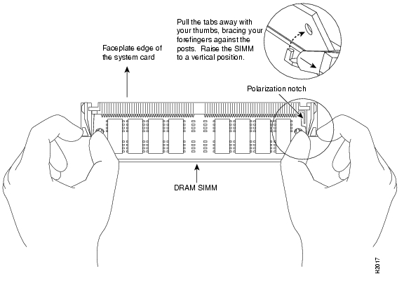
Installing New SIMMs
SIMMs are sensitive components that are susceptible to ESD damage. Handle SIMMs by the edges only; avoid touching the memory modules, pins, or traces (the metal fingers along the connector edge of the SIMM). (See Figure 10.)
Figure 10 Handling a SIMM
CautionTo prevent ESD damage, handle SIMMs as shown in Figure 10.
Follow these steps to install the new SIMMs:
Step 1
Step 2
Step 3
Step 4
Step 5
CautionWhen inserting SIMMs, use firm but not excessive pressure. If you damage a socket, you will have to return the CT3IP to the factory for repair.
Step 6
Step 7
Step 8
This completes the SIMM replacement procedure. Proceed to the section " Replacing the CT3IP SRAM DIMM."
Replacing the CT3IP SRAM DIMM
The SRAM on the CT3IP is contained in a DIMM and located in socket U5. (See Figure 8 on page 44.) If a system problem is determined to be caused by the DIMM, a DIMM replacement might be required. Use the following procedures to replace the SRAM DIMM on your CT3IP.
Note
CautionTo prevent ESD damage, handle the DIMM by the edges only. Place a removed DIMM on an antistatic mat and store it in an antistatic container.
Removing the DIMM
Follow these steps to remove the existing DIMM:
Step 1
Step 2
Step 3
Step 4
Step 5
Figure 11 Releasing the SRAM DIMM
Step 6
This completes the DIMM removal procedure. Proceed to the next section to install the new DIMM.
Installing a New DIMM
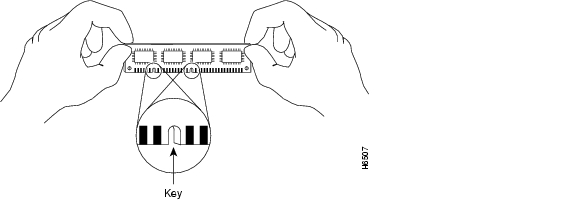
The DIMM is a sensitive component that is susceptible to ESD damage. Handle the DIMM by the edges only; avoid touching the memory modules, pins, or traces (the metal fingers along the connector edge of the DIMM). (See Figure 12.)
Figure 12 Handling an SRAM DIMM
CautionTo prevent ESD damage, handle the DIMM as shown in Figure 12.
Follow these steps to install the new DIMM:
Step 1
Step 2
Step 3
Step 4
CautionWhen inserting the DIMM, use firm but not excessive pressure. If you damage a socket, you will have to return the CT3IP to the factory for repair.
Step 5
Figure 13 Installing an SRAM DIMM in the Socket
Step 6
This completes the DIMM replacement procedure.
Proceed to the section " Installing a CT3IP," on page 16, to replace the CT3IP in the chassis; then restart the system for an installation check. Refer to the section " Checking DRAM and SRAM Replacement."
Checking DRAM and SRAM Replacement
If, after a DRAM or SRAM replacement, the system fails to boot properly, or if the console terminal displays a checksum or memory error, check the following:
•
•
Refer to the section " Using LEDs to Check CT3IP Initialization," on page 18, as required. If after several attempts the system fails to restart properly, contact a service representative for assistance. Before you call, make note of any error messages, unusual LED states, or any other indications that might help solve the problem.
FCC Class A Compliance
This equipment has been tested and found to comply with the limits for a Class A digital device, pursuant to part 15 of the FCC rules. These limits are designed to provide reasonable protection against harmful interference when the equipment is operated in a commercial environment. This equipment generates, uses, and can radiate radio-frequency energy and, if not installed and used in accordance with the instruction manual, may cause harmful interference to radio communications. Operation of this equipment in a residential area is likely to cause harmful interference, in which case users will be required to correct the interference at their own expense.
You can determine whether your equipment is causing interference by turning it off. If the interference stops, it was probably caused by the Cisco equipment or one of its peripheral devices. If the equipment causes interference to radio or television reception, try to correct the interference by using one or more of the following measures:
•
•
•
•
Modifications to this product not authorized by Cisco Systems, Inc. could void the FCC approval and negate your authority to operate the product.
Cisco Connection Online
Cisco Connection Online (CCO) is Cisco Systems' primary, real-time support channel. Maintenance customers and partners can self-register on CCO to obtain additional information and services.
Available 24 hours a day, 7 days a week, CCO provides a wealth of standard and value-added services to Cisco's customers and business partners. CCO services include product information, product documentation, software updates, release notes, technical tips, the Bug Navigator, configuration notes, brochures, descriptions of service offerings, and download access to public and authorized files.
CCO serves a wide variety of users through two interfaces that are updated and enhanced simultaneously: a character-based version and a multimedia version that resides on the World Wide Web (WWW). The character-based CCO supports Zmodem, Kermit, Xmodem, FTP, and Internet e-mail, and it is excellent for quick access to information over lower bandwidths. The WWW version of CCO provides richly formatted documents with photographs, figures, graphics, and video, as well as hyperlinks to related information.
You can access CCO in the following ways:
•
•
•
•
•
For a copy of CCO's Frequently Asked Questions (FAQ), contact cco-help@cisco.com. For additional information, contact cco-team@cisco.com.
Note
DOC-783472=
78-3472-07
![]()
![]()
![]()
![]()
![]()
![]()
![]()
![]()
Posted: Fri Apr 14 15:30:47 PDT 2006
All contents are Copyright © 1992--2006 Cisco Systems, Inc. All rights reserved.
Important Notices and Privacy Statement.