|
|

Table Of Contents
Second Generation Channel Interface Processor (CIP-2) Installation and Configuration
CIP2 Installation Prerequisites
CIP2 Software, Hardware, and Microcode Prerequisites
ECA Software, Hardware, and Microcode Prerequisites
Preventing Electrostatic Discharge Damage
Guidelines for Interface Processor Removal and Installation
What is the Cisco 7000 Series?
What Is the Cisco 7500 Series?
Removing a CIP2 or an Interface Processor Filler
Attaching the CIP2 to the Channel
Checking the CIP2 Installation
CIP2 Microcode Upgrade Overview
Cisco Product Security Overview
Reporting Security Problems in Cisco Products
Obtaining Technical Assistance
Cisco Technical Support & Documentation Website
Definitions of Service Request Severity
Obtaining Additional Publications and Information
Second Generation Channel Interface Processor (CIP-2) Installation and Configuration
Product Numbers: CX-CIP2-ECA1(=), CX-CIP2-ECA2(=), CX-CIP2-ECAP1(=), CX-CIP2-PCA1(=), CX-CIP2-PCA2(=), CX-CIP2-U-ECA1(=), CX-CIP2-U-ECA2(=), CX-CIP2-U-ECAP1(=), CX-CIP2-U-PCA1(=), CX-CIP2-U-PCA2(=), CAB-PCA-Y=, CAB-PCA-VA=, CAB-PCA-VB= <Caveat ID>
This document contains instructions for installing (or replacing) the second-generation Channel Interface Processor (CIP2) in the Cisco 7000 series routers and the Cisco 7500 series routers.
Note
The following Cisco IOS releases support the CIP2: Release 10.2(13) or later, Release 10.3(13) or later, Release 11.0(10) or later, or Release 11.1(5) or later. For earlier releases, CIP2 is supported with a special microcode image.
This microcode image is available through download from Cisco Connection Online (CCO), on disks shipped with the CIP2 when shipped separately from a system (as a spare), or is already in Flash memory on a preconfigured system. (For instructions on placing CIP2 microcode in Flash memory, see the "CIP2 Microcode Guidelines" section.)
We recommend that you load and use the version of CIP2 microcode that is bundled with your Cisco IOS software. If you choose not to, you must then copy a CIP2 microcode image into Flash memory and use a specified configuration command to instruct the Cisco IOS software to use this microcode image instead of the microcode image bundled with your version of the Cisco IOS software; however, this is unnecessary if you load the bundled, recommended CIP2 microcode version.
(For general information on CIP2 microcode, refer to the "CIP2 Microcode Overview" section. For specific instructions on configuring the Cisco IOS software to use a CIP2 microcode image from Flash memory, refer to the "CIP2 Microcode Upgrade Overview" section.)
Note
Your CIP2 might contain a newer hardware version of the ESCON channel adapter (ECA). For additional specific software, hardware, and microcode requirements for the next-generation ECAs, refer to the "ECA Software, Hardware, and Microcode Prerequisites" section. For information on how to determine if your CIP2 contains a newer version of the ECA, refer to the "Verifying the ECA Hardware Version by Examining the ECA Hardware" section or the "Verifying the ECA Hardware Version Using the show controllers cbus Command" section.
For complete and detailed descriptions of CIP2-related interface and configuration commands, configuration options, and requirements, refer to the appropriate configuration and command reference publications listed in the "Related Documentation" section.
Contents
This document includes the following sections:
•
•
•
•
•
Related Documentation
The Cisco IOS software running your router contains extensive features and functionality. The effective use of many of many of these features is easier if you have more information at hand. For additional information on configuring and maintaining the Cisco 7000 series and Cisco 7500 series routers and CIP2, the following documentation resources are available to you:
•
•
–
–
–
–
–
–
–
–
–
–
–
–
–
–
–
–
•
•
CIP2 Installation Prerequisites
Before you install the CIP2, review the safety and electrostatic discharge (ESD)-prevention guidelines in this section to avoid injuring yourself or damaging the equipment. This section also provides a list of parts and tools you will need to perform the installation, and lists the software and microcode requirements.
Following is the specific information included in this section:
•
•
•
•
•
•
CIP2 Software, Hardware, and Microcode Prerequisites
This section provides important prerequisites you should observe regarding CIP2 software, hardware, and microcode.
Following are important software and hardware prerequisites concerning the CIP2:
•
•
Refer to Table 1 for the specific Cisco IOS image names.
•
–
–
•
Caution
Table 1 lists the specific Cisco IOS software release images that are compatible with the CIP2.
Table 1 Cisco IOS Release Image Names
Release 10.21
gs7-k2-mz, gs7-p2-mz
Release 10.3 1
gs7-k2-mz, gs7-p2-mz
rsp-k2-mz, rsp-p2-mzRelease 11.0 1
gs7-k2-mz, gs7-p2-mz, gs7-ak2-mz
rsp-k2-mz, rsp-p2-mz, rsp-ak2-mzRelease 11.0(10)BT
gs7-k2-mz and rsp-k2-mz
Release 11.1 and later
Starting with Release 11.1, all Cisco IOS images that support the CIP also support the CIP2. The images that support the CIP and CIP2 are indicated by the letters j, p, d, and i in the image name.
1 The Cisco IOS Release 10.2, Release 10.3, and Release 11.0 image names that contain a "2" are compatible with the CIP2.
Note
Table 2 specifies the name of the recommended minimum level of CIP2 microcode for a corresponding Cisco IOS release, which should be used if you are using a Cisco IOS release earlier than the Cisco IOS releases listed in the "CIP2 Software, Hardware, and Microcode Prerequisites" section or in the Notes information on page 2.
Table 2 Cisco IOS Releases and CIP2 Microcode Images
10.2
cipp20-8 or later
Not supported
10.3
cipp20-8 or later
Not supported
11.0
cipp21-8 or later
cipp21-14 or later, or cipp-k-22-152 or later
11.1
cip22-6 or later
cip22-15 or later
11.2
cip22-6 or later
cip22-15 or later
11.3
cip25-2 or later
All releases support all ECA hardware versions
12.0
cip26-4 or later
All releases support all ECA hardware versions
1 In general, CIP2 microcode image names that have the prefix "cipp" are compatible with the CIP2.
2 This image is for Cisco IOS Release 11.0(10)BT or later.
The show version and show hardware commands display the current hardware configuration of the router, including the system software version that is currently loaded and running. The show microcode command lists the bundled microcode (target hardware) version for each processor type. The CIP (and now CIP2) microcode is no longer bundled in Cisco IOS 11.1 and later, so the show microcode command lists the default microcode that should be used with this Cisco IOS version. The show controller cbus command shows the microcode version you are running. (For additional descriptions of configuration commands, refer to the publications listed in the "Related Documentation" section.)
You can determine the current version of software or microcode stored in Flash memory either by removing the processor module and checking the Flash device label or by using the show controller cbus command and checking the EPROM version number in the output. (Refer to the "CIP2 Microcode Guidelines" section, for basic configuration information, and to the appropriate software documentation for complete configuration instructions and examples, listed in the "Related Documentation" section.)
If the displays indicate that the required system software and microcode is not available in your system, refer to the "Cisco.com" section, or contact a service representative for upgrade information.
CIP2 Microcode Overview
Microcode, also known as firmware, is a set of processor-specific software instructions that enables and manages the features and functions of a specific processor type. At system startup or reload, the system loads the microcode for each processor type present in the system.
The CIP2 microcode boot image resides in a Flash memory device on the CIP2 motherboard. The entire CIP2 microcode image is delivered on a Flash memory card, on floppy disks, or is available via download from CCO.
New microcode is released to enable new features, improve performance, or fix bugs in earlier versions. The Cisco 7000 series and Cisco 7500 series routers feature downloadable software and microcode for most upgrades. These features enable you to download new (upgraded) images remotely, store the images in router memory, and load the new images at system startup without having to physically access the router. You can store multiple versions for a specific processor type in Flash memory, and use configuration commands to specify which version the system should load at startup. All interfaces of the same type (for example, all CIP2s) use the same microcode image.
Caution
By default, the CIP2 microcode is loaded from either onboard Flash memory (if you have a Cisco 7000 or Cisco 7010 with an RP) or the Flash memory card in slot0 for the Cisco 7500 series routers. The default CIP2 microcode version can be found by entering the show microcode command.
The following is a partial-display example of the show microcode command output:
Router# show microcodeMicrocode bundled in systemCard MicrocodeType Version device:filename---- --------- -------------------(additional display text omitted from this example)CIP2 22-15 slot0:cip22-15(additional display text omitted from this example)Microcode flash default images
Note
ECA Software, Hardware, and Microcode Prerequisites
The ECA/CIP2-motherboard assemblies ship as follows:
•
•
•
(Add an equal sign (=) to the product number when you order interface processors as spares.)
One of three hardware versions of the ECA will be installed on your CIP2. The three hardware versions of the ECA can be used in all Cisco 7000 series and Cisco 7500 series routers. The three versions of the ECA are also compatible with each other and with the CIP2.
However, the second and third ECA hardware versions have specific restrictions regarding the Cisco IOS software release your host Cisco 7000 series or Cisco 7500 series router is running, and the CIP2 microcode images to use that are compatible with the second and third ECA hardware versions and the Cisco IOS software images they require.
For information on determining the ECA hardware version on your CIP2, refer to the "Verifying the ECA Hardware Version by Examining the ECA Hardware" section or the "Verifying the ECA Hardware Version Using the show controllers cbus Command" section.
The following are the specific Cisco IOS software and CIP2 microcode requirements that we recommend you carefully observe before you use the second or third ECA hardware versions installed on your CIP2 card:
•
•
•
•
The appropriate CIP2 microcode images are bundled with the Cisco IOS software.
Verifying the ECA Hardware Version by Examining the ECA Hardware
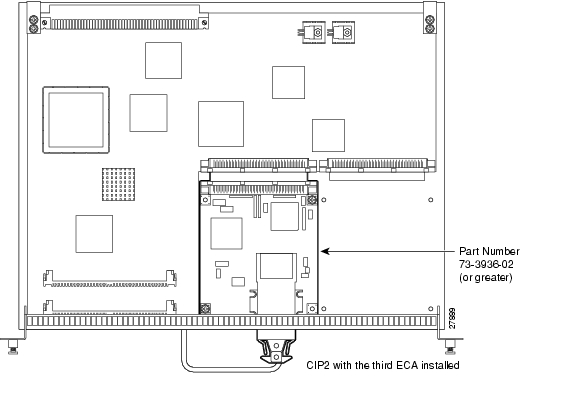
This section contains information on how to determine which hardware version of the ECA is installed on your CIP2. Because ECAs ship under identical product numbers, you must refer to the different part numbers (73-xxxx-xx) and component layouts of the three ESCON channel adapter cards, which are shown in Figure 1, Figure 2 , and Figure 3, then make the appropriate comparisons to the CIP2/ECA assembly shipped to you.
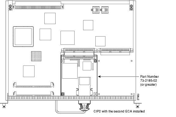
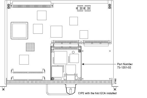
The second and third hardware versions of the ECA are identified by part numbers 72-3936-02 or greater ( Figure 1) or 73-2185-02 or greater ( Figure 2). The first ECA hardware version is part number 73-1201-02 or lower ( Figure 3).
If you determine that you have the second or third ECA hardware version ( Figure 1 or Figure 2), you must observe and comply with the preceding ESCON channel adapter software and microcode prerequisites.
If you determine that you have the first ECA hardware version ( Figure 3), no further action is required.
Figure 1 Third ECA Hardware Version Installed on CIP2
Figure 2 Second ECA Hardware Version Installed on CIP2
Figure 3 First ECA Hardware Version Installed on CIP2
Verifying the ECA Hardware Version Using the show controllers cbus Command
This section provides an alternate method for verifying your ECA's hardware version.
Note
Refer to the arrow in the following partial-display example of the show controllers cbus command; a second or third ECA hardware version is indicated by hw version 02 or hw version 03:
Router# show controllers cbus(additional text omitted from this example)slot0: CIP2, hw 5.0, sw 206.172, ccb 5800FF20, cmdq 48000080, vps 8192software loaded from flash slot0:biff/cip206-172.cbus_kernel_hw5Loaded:seg_eca Rev. 0 Compiled by biff on Mon 10-Feb-97 09:28EPROM version 2.1, VPLD version 5.8—> ECA0: hw version 02, microcode version C50602D4Load metrics:Memory dram 29763656/32MCPU 1m n/a, 5m n/a, 60m n/aDMA 1m n/a, 5m n/a, 60m n/aECA0 1m n/a, 5m n/a, 60m n/aIf the installed ECA is the first ECA hardware version, then hw version 01 or hw version 00 is displayed, as follows:
(additional text omitted from this example)—> ECA0: hw version 01, microcode version C50602D4If the installed ECA is the second ECA hardware version, then hw version 02 is displayed, as follows:
(additional text omitted from this example)—> ECA0: hw version 02, microcode version C50602D4If the installed ECA is the third ECA hardware version, then hw version 03 is displayed, as follows:
(additional text omitted from this example)—> ECA0: hw version 03, microcode version C50602D4
Note
If you determine that you have the first hardware version of the ECA (hw version 00 or hw version 01 is displayed), no further action is required.If you see either of the following sets of error messages displayed, you must upgrade the Cisco IOS software and CIP2 microcode by observing and complying with the ECA Cisco IOS software and microcode prerequisites (refer to Table 2 and the "ECA Software, Hardware, and Microcode Prerequisites" section).
%CIP2-0-MSG:%ADAPTER-0-DIAGFAIL: Port 0 failed the I/O chip tests diagnostic %CIP2-0-MSG: %ADAPTER-0-DIAGDATA: Module Call: 123 Error ID: FF85%CIP2-0-MSG: %ADAPTER-0-DIAGFAIL: Port 0 failed the Electrical wrap diagnostic%CIP2-0-MSG: %ADAPTER-0-DIAGDATA: Module Call: 1221 Error ID: FE14
Note
Safety Guidelines
This section lists safety guidelines you should follow when working with any equipment that connects to electrical power or telephone wiring.
Electrical Equipment
Follow these basic guidelines when working with any electrical equipment:
•
•
•
•
•
•
Telephone Wiring
Use the following guidelines when working with any equipment that is connected to telephone wiring or to other network cabling:
•
•
•
•
Preventing Electrostatic Discharge Damage
Electrostatic Discharge Damage (ESD), which can occur when electronic cards or components are improperly handled, results in complete or intermittent failures.
Following are guidelines for preventing ESD damage:
•
•
•
•
•
•
Caution
Guidelines for Interface Processor Removal and Installation
This section describes mechanical functions of system components, emphasizes the importance of following correct procedures to avoid unnecessary board failures, and is for background only; specific procedures follow in the "CIP2 Hardware Installation" section.
You can remove and replace interface processors while the system is operating; you do not need to notify the software or reset the system power. This functionality enables you to add, remove, or replace interface processors with the system online, which provides a method that is seamless to end users on the network, maintains all routing information, and ensures session preservation.
After an interface processor is reinstalled, the system brings on line only interfaces that match the current configuration and were previously configured as up; all others require that you configure them with the configure command.
Caution
All interface processors have ejector levers that allow you to firmly seat an interface processor in the interface processor slot. The function of the ejector levers is to align and seat the card connectors in the backplane.
Caution
The captive installation screws on the ends of the CIP2 faceplate, when tightened, provide EMI shielding and also help ensure proper seating in the backplane. After using the ejector levers to install a CIP2, tighten the captive installation screws to prevent the CIP2 from becoming partially dislodged from the backplane. These screws must be tightened to meet EMI specifications.
Tools and Parts Required
You need the following tools and parts to install or replace a CIP2. If you need additional equipment, contact a customer service representative for ordering information.
•
•
•
•
•
What is the Cisco 7000 Series?
This section provides an overview of the Cisco 7000 series routers. The Cisco 7000 series consists of the Cisco 7000 and Cisco 7010 routers. The CIP2 operates in the Cisco 7000 series routers.
For specific software and hardware requirements for the Cisco 7000 series systems, refer to the "CIP2 Software, Hardware, and Microcode Prerequisites" section.
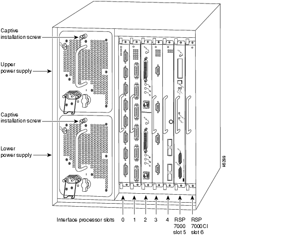
In the Cisco 7000, slot 5 is reserved for the RSP7000 (RSP 7000 slot shown in Figure 4), which contains the system processor and performs packet switching functions; slot 6 is reserved for the RSP7000CI (RSP 7000CI slot shown in Figure 4), which contains all of the environmental monitoring functions for the Cisco 7000. The Cisco 7000 can also be used with the Route Processor (RP) and Switch Processor (SP) or SSP combination.
The remaining five slots (slots 0 through 4) are for interface processors, including the CIP2.
Figure 4 Cisco 7000 with RSP7000 and RSP7000CI Installed Interface Processor
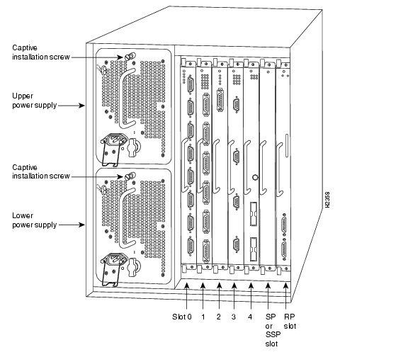
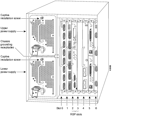
Figure 5 shows the interface processor end of the Cisco 7000, which provides access to the seven processor slots and the removable power supplies. When facing the interface processor end of the chassis, the SP (or SSP) and RP slots are on the far right. The five interface processor slots are numbered 0 to 4 from left to right and are reserved for interface processors, including the CIP2.
Figure 5 Cisco 7000 with RP and SP (or SSP) Installed Interface Processor
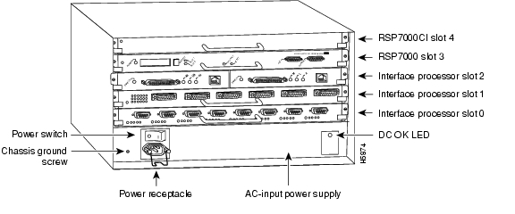
In the Cisco 7010, slot 3 is reserved for the RSP7000 (RSP 7000 slot shown in Figure 6), which contains the system processor and performs packet switching functions; slot 4 is reserved for the RSP7000CI (RSP 7000CI slot shown in Figure 6), which contains all of the environmental monitoring functions for the Cisco 7010. The remaining three slots (slots 0 through 2) are for interface processors, including the CIP2.
Figure 6 Cisco 7010 with RSP7000 and RSP7000CI Installed Interface Processor
Figure 7 shows the interface processor end of the Cisco 7010, which provides access to the five processor slots. When facing the interface processor end of the chassis, the RP and SP (or SSP) slots are at the top. The three interface processor slots are numbered from the bottom up beginning with slot 0 (the bottom slot) through 2 (the center slot) and are reserved for interface processors, including the CIP2.
Figure 7 Cisco 7010 with RP and SP (or SSP) Installed (Interface Processor
What Is the Cisco 7500 Series?
This section provides an overview of the Cisco 7500 series routers. The Cisco 7500 series consists of the Cisco 7505, Cisco 7507, and Cisco 7513 routers. The CIP2 operates in the Cisco 7500 series routers.
For specific software and hardware requirements for the Cisco 7500 series systems, refer to the "CIP2 Software, Hardware, and Microcode Prerequisites" section.
Network interfaces reside on modular interface processors, including the CIP2, which are inserted into interface processor slots and provide a direct connection between external networks and the high-speed CyBus in the Cisco 7500 series. Figure 8, Figure 9, and Figure 10 show the rear of the Cisco 7500 series routers: the five-slot Cisco 7505, the seven-slot Cisco 7507, and the thirteen-slot Cisco 7513, respectively.
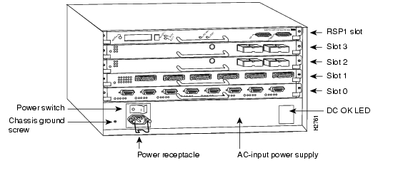
In the Cisco 7505 ( Figure 8), slot 4 is reserved for the Route Switch Processor (RSP1 or RSP4), which contains the system processor and performs packet switching functions. Slots 0 through 3 are for interface processors, including the CIP2.
Figure 8 Cisco 7505 Interface Processor
Figure 9 shows the rear of the Cisco 7507 router. In the Cisco 7507, up to two slots (2 and 3) are reserved for the Route Switch Processor (RSP2 and RSP4), which contains the system processor and performs packet switching functions. Slots 0 and 1 and 4 through 6 are for interface processors, including the CIP2.
Figure 9 Cisco 7507 Interface Processor End
Figure 10 shows the rear of the Cisco 7513. Two slots (6 and 7) are reserved for the second generation Route Switch Processor (RSP2 and/or RSP4), which contains the system processor and performs packet switching functions. Slots 0 through 5 and 8 through 12 are for interface processors, including the CIP2.
Figure 10 Cisco 7513 Interface Processor
What is the CIP2?
This section discusses channel attachment and the CIP2, its LED functions, and its memory and cable requirements.
The following information is included:
–
–
Channel Attachment Overview
A mainframe channel (referred to as a channel) is an intelligent processor that manages the protocol on the communications media and controls the data transfer to and from the main central processing unit (CPU) storage. Devices called input/output processors (IOPs) communicate between the host CPU and the channel. One IOP controls multiple channels, and there is no relationship between the number of CPUs and the number of IOPs.
The channel relieves the mainframe CPU of direct communication with input/output (I/O) devices, which saves processing cycles and allows data processing and communications tasks to run concurrently. Channels use one or more channel paths as the links between mainframes and I/O devices. I/O devices are connected directly to control units, which provide the logical capabilities required to operate and control the I/O devices.
CIP2 Overview
The CIP2 provides up to two channel interfaces for Cisco 7000 series and Cisco 7500 series routers; in some situations, this can eliminate the need for a separate front-end processor (FEP). The CIP2 contains combinations of a bus and tag (also called an original equipment manufacturer's interface [OEMI] and a parallel I/O interface) adapter and an Enterprise Systems Connection (ESCON) adapter. The bus and tag adapter is called the Parallel Channel Adapter (PCA), and the ESCON adapter is called the ESCON Channel Adapter (ECA). (For important information on the ECA hardware versions refer to the "ECA Software, Hardware, and Microcode Prerequisites" section.) The PCA and ECA connect directly to the CIP2, and all combinations of the two adapters are available.
Note
Caution
CIP2 Description
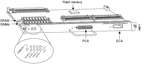
The CIP2 ( Figure 11) consists of a motherboard that is mounted on a metal carrier and one or two ECA and/or PCA interfaces. (The CIP2's front-panel label reads Channel Interface Processor 2.) The ECA and PCA interfaces attach to the motherboard by means of a multipin connector located at the rear edge of the adapter. The ECA and PCA provide the channel attachment interfaces to connect your CIP2 to your channel.
The CIP2 has two DRAM SIMMs and comes configured with 32 MB of DRAM as the minimum standard (default) memory configuration. The CIP2 also has a Flash memory device for storing the CIP2 microcode boot image.
Figure 11 CIP 2
Note
Caution
CIP2 Model Numbers
There are three CIP2 carrier types, which offer the following five interface adapter combinations:
•
•
•
•
•
Add an equal sign (=) to the product number when you order interface processors as spares. For example, the product number for the one PCA on a PCA/ECA carrier if ordered as a spare is CX-CIP2-PCA1(=).
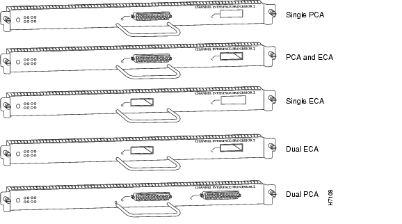
The ECA has a female, duplex connector, and the PCA has a female, DB-78 connector. Figure 12 shows the ECA and PCA interface combinations that are available.
Figure 12 CIP2 Interface Channel Adapter Combinations
Caution
CIP2 DRAM Configurations
Each CIP2 model is available in the following configurations of dynamic random-access memory (DRAM) single in-line memory modules (SIMMs):
•
•
•
•
Note
All CIP2 DRAM upgrade products ship with the configuration note Upgrading DRAM on the CIP2 (Document Number 78-3915-xx, where xx is the latest version of the document). This configuration note is also available on the Documentation CD-ROM.
CIP2 DRAM can be upgraded in the field by Cisco-certified service personnel only.CIP2 LED Indicators and Sequences
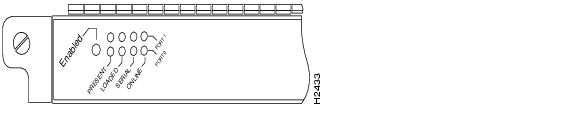
Following are the functions of the CIP2 LEDs ( Figure 13):
•
•
•
•
•
Figure 13 CIP2 LED Indicators
The following are the sequences for the CIP2 LED indicators. The enabled LED is not part of the following sequences. On cold boots, the following LED sequences apply:
The following LED sequence indicates that the CIP2 is waiting for commands from the RP (or RSP).
On warm boots, the LEDs flash briefly. On downloads, the following three LED sequences apply; the first indicates that the system is downloading volatile programmable logic device (VPLD) code.
The following sequence indicates that the CIP2 is downloading microcode:
The following sequence indicates that the CIP2 is starting to execute the microcode:
ESCON and Bus and Tag Specifications
Table 3 lists the specifications for the ESCON and bus and tag interfaces.
Table 3 ESCON and Bus and Tag Interfaces
Supported processor I/O architectures
ESA/390
System/370
370/Xa
ESA/390Bit transmission
Serial
Parallel
Maximum distance (for LED with ESCON)
1.9 miles (3.1 km) point-to-point
5.7 miles (9.2 km) with two ESCON Directors400 ft (122 m)1
Channel data rate
Up to 17 MBps2
Up to 4.5 MBps
Signaling rate3
200 Mbps4
4.5 MBps
Cable types
Fiber-optic (62.5/125 micron multimode)
Copper bus and tag
Addition of devices to running systems
Dynamic5
Static
Number of addressable devices per channel
256 x 16 x 16 x 2536
256
Connectable control units per channel
Up to 59 (through a 9032 ESCON Director)
Up to 8
Connectable channels per adapter
Up to 59 (through a 9032 ESCON Director)
Varies by control unit1
1 The IBM 3044 C/D (host side/remote side) copper-to-fiber repeater can be used to extend this distance up to 1.2 miles (2 km).
2 MBps = megabytes per second.
3 For bus and tag, the signaling rate matches the channel data rate. For example, if you use a 3.0 MBps channel, the signaling rate is 3.0 MBps. The ESCON interface signals at a constant rate; the bus and tag interface signals at the data rate.
4 Mbps = megabits per second.
5 The CIP2 ESCON requires dynamic = NO with HCD.
6 Where 256 represents available unit addresses, 16 represents the number of partitions (LPARs), 16 represents the number of control unit images, and 253 represents the number of ESCON director paths. It is unlikely a system would have the resources to support the total number of available addresses.
ESCON Cable
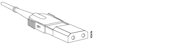
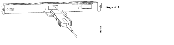
The ECA interface uses 62.5/125 micrometer, multimode, fiber-optic cable with male duplex connectors at each end ( Figure 14). ESCON cables are not available from Cisco. Refer to the ESCON specifications in Table 3, and contact your cable supplier or the vendor of your host CPU to order the correct ESCON cable.
Figure 14 ESCON Interface Duplex Connector for the ECA
Bus and Tag Cables
Following are descriptions and illustrations of the bus and tag cables.
Y Cable
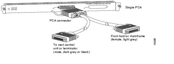
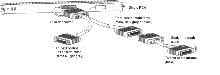
The bus and tag cable with three 78-pin connectors ( Figure 15) has a DB-78 male (PCA) connector on the CIP2 end, a DB-78 female connector on the next-control-unit end, and a DB-78 male connector on the from-host end.
Figure 15 PCA Bus and Tag Cable (Y Cable)
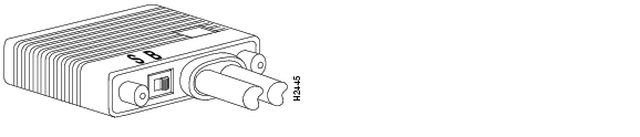
The bus and tag model number is CAB-PCA-Y (referred to as the Y cable). The male connector might be labeled IN and is typically black, but can also be a dark gray. The female connector might be labeled OUT and is typically light gray. The female OUT cable is nearest to the select/bypass switch, which is shown in Figure 16. (The IBM part number is 89F8392; however, this number is subject to change.)
Caution
Note
Caution
Figure 16 Select/Bypass Switch on the Rear of the PCA Connector (CAB-PCA-Y Bypass Shown
In select mode the PCA is operational, and the select-out signal is passed in a loop to all control lines on the channel. All control units have a relay that shorts the incoming select-out signal to the outgoing select-out signal when power is not applied to the control unit. When power is applied, the relay is opened, and the signal is passed to the PCA.
Without the select/bypass switch in bypass mode, the channel would need to be taken offline before servicing or replacing a CIP2. If the selected address does not match, the select-out signal is passed to the next control unit. If the select-out signal gets all the way back to the channel, the control unit being addressed is not present.
Note
Caution
VA and VB Cables
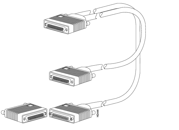
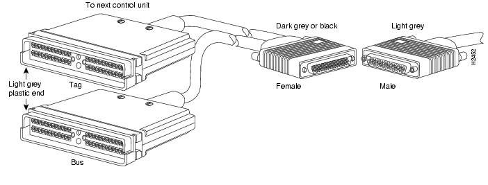
The two bus and tag cables with connector blocks have a DB-78 (male or female) connector on the CIP2 end and 48-pin type-A connector blocks on the bus and tag ends ( Figure 17). VA and VB cables are 56 inches (1.42 meters) in length.
For the bus and tag cable that attaches between the host and the PCA, the model number is CAB-PCA-VA, and it is referred to as the VA cable. The female 78-pin connector might be labeled IN and is typically light gray. The cable labeled P2 is bus, and the cable labeled P3 is tag. Looking into the end of the female 78-pin connector (on the VA cable), with the wide part of the connector D-shell on top, the P2 (bus) cable is on the right, and the P3 (tag) cable is on the left. The plastic on the ends of the bus and tag connectors might be black or dark gray.
The IBM part number is 12G8058; however, this number is subject to change. The VA cable ships with a terminator; the Cisco model number CAB-PCA-VA includes this terminator. The terminator and VA cable together have the IBM part number 12G7988; however, this number is subject to change.
For the bus and tag cable that attaches between the next control unit and the PCA, the model number is CAB-PCA-VB, and it is referred to as the VB cable. The male 78-pin connector might be labeled OUT and is typically black or dark gray. The cable labeled P2 is bus, and the cable labeled P3 is tag. Looking into the end of the male 78-pin connector (on the VB cable), with the wide part of the connector D-shell on top, the P2 (bus) cable is on the left, and the P3 (tag) cable is on the right. The plastic on the ends of the bus and tag connectors might be light gray (as opposed to the black or dark gray plastic on the VA cable). The IBM part number is 12G7933; however, this number is subject to change.
Caution
Figure 17 PCA Bus and Tag, VA and VB Cables
The Y cable always attaches to the PCA. The VA cable attaches between the male end of the Y cable and the host. The VB cable attaches between the female end of the Y cable and the next (or new) control unit. Do not connect the VB cable directly to the PCA. If the PCA is the last control unit, channel termination is required at the end of the Y cable that points away from the host ( Figure 15). For attachment instructions refer to the "Attaching the CIP2 to the Channel" section.
Caution
CIP2 Hardware Installation
The following sections describe the procedures for installing or replacing the CIP2:
•
•
Caution
Before installing a newCIP2, ensure that your system meets the minimum software and microcode requirements described in the "CIP2 Software, Hardware, and Microcode Prerequisites" section and "CIP2 Microcode Overview" section.
While you can remove and install a CIP2 without turning off system power, we do recommend that you administratively shut down CIP2 interface before insertion and removal. In any case, you must follow the insertion instructions carefully; for example, failure to use the ejector levers or insert the CIP2 properly can cause system error messages indicating a card failure.
Each unused interface processor slot contains an interface processor filler (which is an interface processor carrier without an interface card) to keep dust out of the chassis and to maintain proper airflow through the interface processor compartment.
If you install a new CIP2, select an empty interface processor slot and remove the interface processor filler. If you replace a CIP2, you can retain the existing interface configuration by removing the existing interface processor and installing the new one in the same slot; however, the new CIP2 must have the same channel adapter configuration as the CIP2 you replaced.
Proceed to the "Removing a CIP2 or an Interface Processor Filler" section for instructions on making an interface processor slot available for the new CIP2, then to the "Installing a CIP2" section for the installation instructions. After the new CIP2 is secure, follow the procedures in the "Checking the CIP2 Installation" section to verify that it is installed and functioning properly.
Removing a CIP2 or an Interface Processor Filler
You do not need to shut down the interface or the system power when you remove a CIP2; however, to prevent a possible interface control check on the mainframe, consult with your system administrator to take appropriate precautions. If you are installing a new CIP2, select an available slot and remove the interface processor filler. If you are replacing a CIP2, first remove the existing CIP2 and immediately place it component side up on an antistatic surface, then insert the new CIP2 in the same slot to retain the previous configuration for the new channel interface.
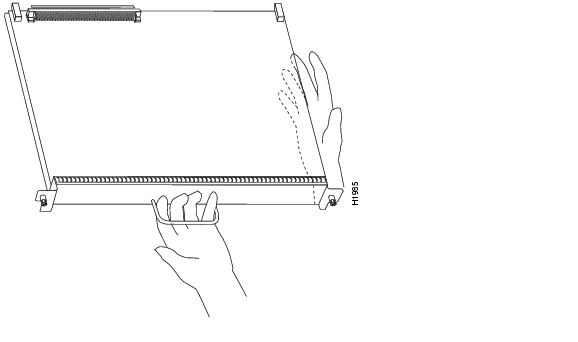
Figure 18 shows proper handling of an interface processor for installation in the Cisco 7010 or Cisco 7505 models. The processor slots are oriented horizontally in the Cisco 7010 and Cisco 7505, and vertically in the Cisco 7000, Cisco 7507, and Cisco 7513. When installing interface processors in these latter chassis, handle the interface processor in the same manner, but rotated 90 degrees clockwise.
Figure 18 Handling Interface Processors During Installation
Figure 19 shows the functions of the ejector levers in the correct orientation for the horizontal processor slots in a Cisco 7010 and Cisco 7505 chassis. In a Cisco 7000, Cisco 7507, and Cisco 7513 chassis, the function of the ejector levers is the same, but the orientation is rotated 90 degrees clockwise for the vertical processor slots.
Figure 19 Function of the Ejector Levers
The function of the ejector levers is to align and seat the card connectors in the backplane. Failure to use the ejector levers and insert the interface processor properly can disrupt the order in which the pins make contact with the backplane.
Following are examples of incorrect insertion practices and their results:
•
•
•
•
Using the ejector levers and making sure that they are pushed fully into position ensures that all three layers of pins are mated with (or free from) the backplane.
It is also important to use the ejector levers when you remove an interface processor to ensure that the card connector pins disconnect from the backplane in the logical sequence expected by the system. Any processor module that is only partially connected to the backplane can halt the bus.
In the following procedures, two channel-related terms are used: vary offline refers to disabling an interface; vary online refers to enabling an interface. For instructions on how to vary the host channel or addresses online or offline, refer to the documentation for your mainframe operating system.
Refer to Figure 19 while performing the following steps to remove a CIP2 or interface processor filler. If you are removing an interface processor filler, proceed to Step 5. If you are replacing an existing CIP2, begin at Step 1.
Follow these steps to remove a CIP2 or an interface processor filler:
Step 1
Step 2
Step 3
Step 4
Step 5
Step 6
Step 7
Step 8
Step 9
Proceed to the next section to install a new CIP2.
Installing a CIP2
The CIP2 slides into any available interface processor slot and connects directly to the backplane of the Cisco 7000 series or Cisco 7500 series router. The backplane slots are keyed so that the CIP2 can be installed only in an interface processor slot. (Refer to Figure 4, Figure 6, Figure 8, Figure 9, or Figure 10, depending on your chassis type.) Figure 19 shows the functional details of inserting an interface processor and using the ejector levers. Figure 18 shows proper handling of an interface processor during installation.
Caution
Follow these steps to install a CIP2:
Step 1
Step 2
Step 3
Step 4
Step 5
Caution
Step 6
Step 7
Proceed to the next section to attach the bus and tag or ESCON cables between the CIP2 interface ports and your channel.
Attaching the CIP2 to the Channel
The CIP2 can be connected to the channel using the bus and tag cables (for the PCA) or using a fiber-optic ESCON cable with duplex connectors (for the ECA). Bus and tag and ESCON connections each have their own special requirements.
The following sections discuss bus and tag and ESCON connections:
•
Attaching the Bus and Tag Cables
The PCA is connected using the bus and tag cable with 78-pin connectors (the Y cable) and the bus and tag cables with 48-pin, type A connector blocks (the VA and VB cables). In general, a Y cable attaches to the PCA on the CIP2, and the VA and VB cables attach to the remaining ends of the Y cable.
Attaching the PCA to the Host Channel
Attach the PCA to the host as follows:
Caution
Step 1
For instructions on how to vary the host channel offline, refer to the documentation for your mainframe operating system.
Caution
Step 2
Figure 20 Connecting or Removing the Y Cable
Step 3
If the PCA is the last control unit on the channel, attach a terminator to the female end of the Y cable ( Figure 20b). Do not attach a VB cable.
Note
Caution
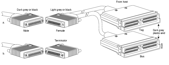
Figure 21 Connecting the VB Cable Between the Y Cable and the Next Control Unit
Step 4
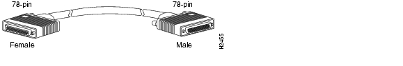
Figure 22 Straight-Through Cable
Step 5
Figure 23 Connecting the VA Cable Between the Y Cable and the Host
Step 6
Step 7
Step 8
Step 9
Step 10
Figure 24 C
Caution
Detaching the Y Cable from the PCA
To properly detach a Y cable from the PCA, use the following procedure.
Caution
Step 1
Step 2
Caution
Step 3
Step 4
Step 5
Step 6
Caution
Attaching the ESCON Cable
Following is the procedure for attaching the ESCON cable between the ECA and the host channel.
Caution
Step 1
Step 2
Figure 25 Connecting an ESCON Cable to the ECA
Step 3
This completes the procedure for attaching an ESCON cable.
Checking the CIP2 Installation
After you install the CIP2 and cables, verify the installation by observing the LED states and the console display. When the system has reinitialized all inserted interfaces, the enabled LED on the newly inserted CIP2 should go on. The console screen will also display a message as the system discovers each interface during its reinitialization. If you need to verify the operation of the interfaces, refer to the "Running CIP2 Diagnostic Tests" section.
When you remove and replace interface processors, the system provides status messages on the console screen. These messages are for information only. The following sample display shows the events logged by the system as a CIP2 is removed from slot 1; the system makes as down the CIP2 that was removed. If the appropriate cables are connected and the no shutdown command is entered after the CIP2 is reinserted, the system marks the interface(s) as up again.
The sample display follows:
Router#%OIR-6-REMCARD: Card removed from slot 1, interfaces disabledRouter#%OIR-6-INSCARD: Card inserted in slot 1, interfaces administratively shut downWhen a new CIP2 is inserted or when a CIP2 is moved to a new slot, the system recognizes the new interface, but leaves it in an administratively shutdown state until you configure it and change the state to up with the no shutdown command.
The following sample display shows the events logged by the system as a new single-PCA CIP2 is inserted in slot 3:
Router#%OIR-6-INSCARD: Card inserted in slot 3, interfaces administratively shut downVerify that the CIP2 is installed correctly, as follows:
Step 1
•
•
•
Step 2
Step 3
Figure 26 CIP2 LED Indicators
If the enabled LED does go on, the installation check is complete.
If the enabled LED on the CIP2 fails to go on, the CIP2 card connector might not be fully seated in the backplane or the correct version of CIP2 microcode was not available for download. To check the CIP2 card's connections, proceed to Step 4. To check the microcode, use the show microcode command, the show controllers cbus command, or the dir slot0 command.
Step 4
•
•
•
•
Step 5
•
•
•
Step 6
Step 7
If this installation was to replace a CIP2, use the show interfaces or show controllers cxbus EXEC commands to verify the status of the interface. (For complete descriptions of the show commands, refer to the publications listed in the "Related Documentation" section.)
If an error message is displayed on the console terminal, refer to the System Error Messages publication for error message definitions. If you experience other problems that you are unable to solve, contact a service representative for assistance.
This completes the CIP2 hardware installation.
Note
CIP2 Microcode Guidelines
The following sections discuss CIP2 microcode configuration requirements:
•
•
(For additional information about specific microcode requirements, refer to the " "ECA Software, Hardware, and Microcode Prerequisites" section.)
How Does CIP Microcode Ship?
For the Cisco 7000 series and Cisco 7500 series routers, CIP2 microcode is available on floppy disks, Flash memory cards (which also include the Cisco IOS release compatible with the microcode version), and via Cisco Connection Online (CCO).
As of Cisco IOS Release 11.1, the CIP2 microcode is shipped or available on the following media:
•
•
•
•
Note
CIP2 Microcode Upgrade Overview
Following is an overview of what you need to do to upgrade unbundled CIP2 microcode (that shipped on floppy disks and Flash memory cards) for the Cisco 7000 series and Cisco 7500 series routers.
Caution
Upgrading from Floppy Disks
For CIP2 microcode images that shipped on floppy disks or were obtained from CCO, do the following:
Step 1
Step 2
Step 3
Note
Install the new ROMs, then proceed to Step 6.Step 4
Step 5
Step 6
Note
Step 7
Step 8
Step 9
Step 10
Upgrading from a Flash Memory Card
For CIP2 microcode that shipped on Flash memory cards, do the following:
Step 1
Step 2
Note
The Upgrading Software and Microcode in Cisco 7000 Series and Cisco 7500 Series Routers publication includes information on upgrading software and microcode images, transferring files to and from Trivial File Transfer Protocol (TFTP) servers, copying files between nonvolatile random-access memory (NVRAM) and Flash memory, and between TFTP servers and Flash memory; the publication also includes basic instructions for booting your system.Configuring Microcode
This section describes how to modify the startup configuration to load different microcode images at startup, or to change existing configuration instructions and reenable the system default.
At system startup or reload, the system loads a microcode image for each processor type. All processors of the same type use the same microcode image; only one image for each type can load at startup. The CIP2 Flash memory provides a CIP2 microcode boot image. The entire CIP2 microcode image is located in a Flash memory card, on a floppy disk, or is available from CCO or from a TFTP server.
Whenever you upgrade software or microcode by downloading new images into Flash memory, you must configure the system to load the new image at startup. Otherwise, the system will continue to load the default image from the system, or attempt to load the previous image (if any) if it is still specified in the configuration file.
Note
To instruct the system to boot a CIP2 microcode image other than the default at startup, use the microcode cip flash [bootflash | slot0 | slot1 ]:filename configuration command to add the instructions to the configuration file.
Note
If you plan to load a microcode image from an individual file or a bundled system image stored in Flash memory, enter the show flash slot0: EXEC command to display the contents and verify the exact name of the file (cip1234 is used in this example):
Router> show flash slot0:(additional displayed text omitted)-#- ED --type-- --crc--- -seek-- nlen -length- -----date/time------ name1 .. FFFFFFFF A831B720 3828CC 16 3549260 Feb 24 1996 20:28:56 rsp-k-mz.111-52 .. FFFFFFFF 83A6447F 8B8D18 16 761932 Apr 17 1996 15:15:59 cip1234(additional displayed text omitted)5419388 bytes available (15158916 bytes used)Follow these steps to configure the microcode for a CIP2 on a router configured with Cisco IOS Release 11.1(5) or later.
Step 1
Router> enablePassword:Router#
Note
Step 2
Step 3
Router# configure terminalTo load the microcode from an individual microcode image that is stored as a file in Flash memory, enter the microcode command, the processor type, the specific memory location of the CIP2 microcode image, and the exact argument for filename (cip1234 is used in this example):
Router(config)# microcode cip flash slot0:cip1234The no microcode command cancels any existing instructions to load an image from Flash memory:
Router(config)# no microcode cip flash slot0:cip1234Step 4
Router# copy running-config startup-configThe microcode reload command must be invoked whenever you modify the system default to load a microcode image, using the microcode cip flash command.
If you see either of the following sets of error messages displayed, you must upgrade the Cisco IOS software and CIP2 microcode by observing and complying with the ESCON channel adapter Cisco IOS software and microcode prerequisites; refer to Table 2 and the "ECA Software, Hardware, and Microcode Prerequisites" section.
%CIP2-0-MSG: %ADAPTER-0-DIAGFAIL: Port 0 failed the I/O chip tests diagnostic
%CIP2-0-MSG: %ADAPTER-0-DIAGDATA: Module Call: 123 Error ID: FF85
%CIP2-0-MSG: %ADAPTER-0-DIAGFAIL: Port 0 failed the Electrical wrap diagnostic%CIP2-0-MSG: %ADAPTER-0-DIAGDATA: Module Call: 1221 Error ID: FE14
Note
Step 5
Step 6
This completes the procedure for configuring microcode. For complete descriptions of the show commands, refer to the publications listed in the "Related Documentation" section.
Using Flash Memory
The following sections discuss various Flash-memory functionality that you might need for microcode configuration:
•
•
•
Copying to Flash Memory on an RSP or RSP7000
Copying a new image to Flash memory might be required whenever a new microcode image becomes available. Use the command copy tftp:filename [ bootflash | slot0 | slot1 ]:filename for the copy procedure where tftp:filename is the source of the file and [ bootflash | slot0 | slot1 ]:filename is the destination in onboard Flash memory or on either of the Flash memory cards. An example of the copy tftp:filename command for Cisco IOS Release 11.1 follows:
Router# copy tftp:cip1234 slot0:cip12342283972 bytes available on device flash, proceed? [confirm]Address or name of remote host [biff.cisco.com]?Accessing file "cip1234" on biff.cisco.com ...FOUNDLoading mhoerler/cip1234 from 1.1.1.22 (via Ethernet0/0): !Verifying via checksum...Flash verification successful. Length = 1, checksum = 0xFFFF--- expanding multi-segment file ---flash:cip1234_kernel_hw4 size = 238626!!!!!!!!!!!!!!!!!!!!!!!!!Verifying via checksum... vvvvvvvvvvvvvvFlash verification successful. Length = 238626, checksum = 0x0000--- expanding multi-segment file ---flash:cip1234_seg_802 size = 198600!!!!!!!!!!!!!!!!!!!!!!!!!Verifying via checksum... vvvvvvvvvvvvFlash verification successful. Length = 198600, checksum = 0x9237--- expanding multi-segment file ---flash:cip1234_seg_csna size = 102392!!!!!!!!!!!!!!!!!!!!Verifying via checksum... vvvvvvFlash verification successful. Length = 102392, checksum = 0x771E--- expanding multi-segment file ---flash:cip1234_seg_eca size = 461408!!!!!!!!!!!!!!!!!!!!!!!!!!!!!!! Verifying via checksum... vvvvvvvvvvvvvvvvvvvvvvvvvvvvFlash verification successful. Length = 461408, checksum = 0xB791--- expanding multi-segment file ---flash:cip1234_seg_offload size = 52608!!!!!!!!!!Verifying via checksum... vvvFlash verification successful. Length = 52608, checksum = 0x0FBC--- expanding multi-segment file ---flash:cip1234_seg_pca size = 69360!!!!!!!!!!!!!!Verifying via checksum... vvvvFlash verification successful. Length = 69360, checksum = 0x737F--- expanding multi-segment file ---flash:cip1234_seg_tcpip size = 175320!!!!!!!!!!!!!!!!!!!!!!!!!!!!!!!!!!Verifying via checksum... vvvvvvvvvvFlash verification successful. Length = 175320, checksum = 0xD416
Note
Additional Flash Memory Commands
Following are additional commands related to the Flash memory in the single in-line memory module (SIMM) on the RSP1, RSP2 and RSP7000 (called bootflash) and in PCMCIA Flash memory cards. (The following example assumes you are currently accessing the Flash memory card in PCMCIA slot 0.) You can determine which PCMCIA slot you are accessing using the pwd command as follows:
Router# pwdslot0You can move between Flash memory media using the cd [ bootflash | slot0 | slot1 ] command as follows:
Router# cd slot0slot0Router# cd slot1Router# pwdslot1You can list the directory of any Flash memory media using the dir [ bootflash | slot0 | slot1 ] command as follows:
Router# dir-#- -length- -----date/time------ name1 4601977 May 19 1994 09:42:19 myfile16 679 May 19 1994 05:43:56 todays-config7 1 May 19 1994 09:54:53 fun1You can delete a file from any Flash memory media using the delete command as follows:
Router# delete slot0:fun1Router# dir-#- -length- -----date/time------ name1 4601977 May 19 1994 09:42:19 myfile16 679 May 19 1994 05:43:56 todays-configTo verify that the delete command was successful, use the dir/all/long command.
Note
The squeeze command permanently removes files, which are marked as deleted, and pushes all other undeleted files together to eliminate spaces between them.
Following is the syntax of the squeeze command:
Router# squeeze slot0:All deleted files will be removed, proceed? [confirm]Squeeze operation may take a while, proceed? [confirm]ebESZTo prevent loss of data due to sudden power loss, the "squeezed" data is temporarily saved to another location of Flash memory, which is specially used by the system.
In the preceding command display output, the character "e" means this special location has been erased (which must be performed before any write operation). The character "b" means that the data that is about to be written to this special location has been temporarily copied. The character "E" signifies that the sector which was temporarily occupied by the data has been erased. The character "S" signifies that the data was written to its permanent location in Flash memory.
The squeeze command operation keeps a log of which of these functions has been performed so upon sudden power failure, it can come back to the right place and continue with the process. The character "Z" means this log was erased after the successful squeeze command operation.
Recovering from Locked Blocks
A locked block of Flash memory occurs when power is lost or a Flash memory card is unplugged during a write or erase operation. When a block of Flash memory is locked, it cannot be written to or erased, and the operation will consistently fail at a particular block location. The only way to recover from locked blocks is by reformatting the Flash memory card with the format command.
Caution
Running CIP2 Diagnostic Tests
There are six PCA and ECA diagnostic test routines, as follows:
•
•
•
•
•
•
The external wrap routine runs in two modes: optical and electrical.
Note
The interface has to pass the first five tests. The sixth test (which is the same as the fifth, but with a different mode for the optical wrap plug for the ECA, instead of electrically wrapping the interface) will fail if no wrap plug is installed or if the interface is connected to the channel. This type of failure will not affect the channel.
If a wrap plug is inserted, following is how the wrap diagnostics will be repeated:
•
•
•
If you suspect that an adapter might be the cause of a problem you are seeing, you can run a single pass of the diagnostic tests on an installed PCA or ECA interface by entering configuration mode and specifying that the console terminal will be the source of the configuration subcommands, as follows:
Router# configure terminalNext, specify the slot/port number (interface processor slot number/port number) of the interface for which you want the diagnostic tests to run by entering the interface channel command followed by the slot/port of the interface.
The example that follows is for a CIP2 interface in interface processor slot 1:
Router(config)# interface channel 1/0To run the diagnostic tests once, enter the shutdown command and then the no shutdown command, as follows:
Router(config)# shutdownRouter(config)# no shutdownCtrl-ZRouter#The no shutdown command causes the diagnostic tests to run on the PCA or ECA interface you selected. If no failures occur, you can rule out that adapter as the source of your problem.
Obtaining Documentation
Cisco documentation and additional literature are available on Cisco.com. Cisco also provides several ways to obtain technical assistance and other technical resources. These sections explain how to obtain technical information from Cisco Systems.
Cisco.com
You can access the most current Cisco documentation at this URL:
http://www.cisco.com/techsupport
You can access the Cisco website at this URL:
You can access international Cisco websites at this URL:
http://www.cisco.com/public/countries_languages.shtml
Product Documentation DVD
The Product Documentation DVD is a comprehensive library of technical product documentation on a portable medium. The DVD enables you to access multiple versions of installation, configuration, and command guides for Cisco hardware and software products. With the DVD, you have access to the same HTML documentation that is found on the Cisco website without being connected to the Internet. Certain products also have .PDF versions of the documentation available.
The Product Documentation DVD is available as a single unit or as a subscription. Registered Cisco.com users (Cisco direct customers) can order a Product Documentation DVD (product number DOC-DOCDVD= or DOC-DOCDVD=SUB) from Cisco Marketplace at this URL:
http://www.cisco.com/go/marketplace/
Ordering Documentation
Registered Cisco.com users may order Cisco documentation at the Product Documentation Store in the Cisco Marketplace at this URL:
http://www.cisco.com/go/marketplace/
Nonregistered Cisco.com users can order technical documentation from 8:00 a.m. to 5:00 p.m. (0800 to 1700) PDT by calling 1 866 463-3487 in the United States and Canada, or elsewhere by calling 011 408 519-5055. You can also order documentation by e-mail at tech-doc-store-mkpl@external.cisco.com or by fax at 1 408 519-5001 in the United States and Canada, or elsewhere at 011 408 519-5001.
Documentation Feedback
You can rate and provide feedback about Cisco technical documents by completing the online feedback form that appears with the technical documents on Cisco.com.
You can submit comments about Cisco documentation by using the response card (if present) behind the front cover of your document or by writing to the following address:
Cisco Systems
Attn: Customer Document Ordering
170 West Tasman Drive
San Jose, CA 95134-9883We appreciate your comments.
Cisco Product Security Overview
Cisco provides a free online Security Vulnerability Policy portal at this URL:
http://www.cisco.com/en/US/products/products_security_vulnerability_policy.html
From this site, you will find information about how to:
•
•
•
A current list of security advisories, security notices, and security responses for Cisco products is available at this URL:
To see security advisories, security notices, and security responses as they are updated in real time, you can subscribe to the Product Security Incident Response Team Really Simple Syndication (PSIRT RSS) feed. Information about how to subscribe to the PSIRT RSS feed is found at this URL:
http://www.cisco.com/en/US/products/products_psirt_rss_feed.html
Reporting Security Problems in Cisco Products
Cisco is committed to delivering secure products. We test our products internally before we release them, and we strive to correct all vulnerabilities quickly. If you think that you have identified a vulnerability in a Cisco product, contact PSIRT:
•
An emergency is either a condition in which a system is under active attack or a condition for which a severe and urgent security vulnerability should be reported. All other conditions are considered nonemergencies.
•
In an emergency, you can also reach PSIRT by telephone:
•
•
Tip
Never use a revoked or an expired encryption key. The correct public key to use in your correspondence with PSIRT is the one linked in the Contact Summary section of the Security Vulnerability Policy page at this URL:
http://www.cisco.com/en/US/products/products_security_vulnerability_policy.html
The link on this page has the current PGP key ID in use.
If you do not have or use PGP, contact PSIRT at the aforementioned e-mail addresses or phone numbers before sending any sensitive material to find other means of encrypting the data.
Obtaining Technical Assistance
Cisco Technical Support provides 24-hour-a-day award-winning technical assistance. The Cisco Technical Support & Documentation website on Cisco.com features extensive online support resources. In addition, if you have a valid Cisco service contract, Cisco Technical Assistance Center (TAC) engineers provide telephone support. If you do not have a valid Cisco service contract, contact your reseller.
Cisco Technical Support & Documentation Website
The Cisco Technical Support & Documentation website provides online documents and tools for troubleshooting and resolving technical issues with Cisco products and technologies. The website is available 24 hours a day, at this URL:
http://www.cisco.com/techsupport
Access to all tools on the Cisco Technical Support & Documentation website requires a Cisco.com user ID and password. If you have a valid service contract but do not have a user ID or password, you can register at this URL:
http://tools.cisco.com/RPF/register/register.do
Note
Submitting a Service Request
Using the online TAC Service Request Tool is the fastest way to open S3 and S4 service requests. (S3 and S4 service requests are those in which your network is minimally impaired or for which you require product information.) After you describe your situation, the TAC Service Request Tool provides recommended solutions. If your issue is not resolved using the recommended resources, your service request is assigned to a Cisco engineer. The TAC Service Request Tool is located at this URL:
http://www.cisco.com/techsupport/servicerequest
For S1 or S2 service requests, or if you do not have Internet access, contact the Cisco TAC by telephone. (S1 or S2 service requests are those in which your production network is down or severely degraded.) Cisco engineers are assigned immediately to S1 and S2 service requests to help keep your business operations running smoothly.
To open a service request by telephone, use one of the following numbers:
Asia-Pacific: +61 2 8446 7411 (Australia: 1 800 805 227)
EMEA: +32 2 704 55 55
USA: 1 800 553-2447For a complete list of Cisco TAC contacts, go to this URL:
http://www.cisco.com/techsupport/contacts
Definitions of Service Request Severity
To ensure that all service requests are reported in a standard format, Cisco has established severity definitions.
Severity 1 (S1)—An existing network is down, or there is a critical impact to your business operations. You and Cisco will commit all necessary resources around the clock to resolve the situation.
Severity 2 (S2)—Operation of an existing network is severely degraded, or significant aspects of your business operations are negatively affected by inadequate performance of Cisco products. You and Cisco will commit full-time resources during normal business hours to resolve the situation.
Severity 3 (S3)—Operational performance of the network is impaired, while most business operations remain functional. You and Cisco will commit resources during normal business hours to restore service to satisfactory levels.
Severity 4 (S4)—You require information or assistance with Cisco product capabilities, installation, or configuration. There is little or no effect on your business operations.
Obtaining Additional Publications and Information
Information about Cisco products, technologies, and network solutions is available from various online and printed sources.
•
•
http://www.cisco.com/go/marketplace/
•
•
•
http://www.cisco.com/go/iqmagazine
or view the digital edition at this URL:
http://ciscoiq.texterity.com/ciscoiq/sample/
•
•
http://www.cisco.com/en/US/products/index.html
•
http://www.cisco.com/discuss/networking
•
http://www.cisco.com/en/US/learning/index.html
This document is to be used in conjunction with the documents listed in the "Related Documentation" section.
Any Internet Protocol (IP) addresses used in this document are not intended to be actual addresses. Any examples, command display output, and figures included in the document are shown for illustrative purposes only. Any use of actual IP addresses in illustrative content is unintentional and coincidental.
© <year> Cisco Systems, Inc. All rights reserved.
Printed in the USA on recycled paper containing 10% postconsumer waste.
![]()
![]()
![]()
![]()
![]()
![]()
![]()
![]()
Posted: Tue May 2 17:41:07 PDT 2006
All contents are Copyright © 1992--2006 Cisco Systems, Inc. All rights reserved.
Important Notices and Privacy Statement.