|
|

Table Of Contents
Flash Memory Card Installation Instructions
Preventing Electrostatic Discharge Damage
Flash Memory Card Product Numbers
Flash Memory Card Compatibility and Software Prerequisites
RSP4- and RSP8-Specific Flash Memory Card Compatibility Requirements and Examples
Locating the RP, RSP7000, RSP1, RSP2, RSP4, or RSP8
Installing and Removing a Flash Memory Card (RSP and RSP7000 Only)
Formatting a Flash Memory Card (RSP and RSP7000 Only)
Installing and Removing a Flash Memory Card (RP Only)
Formatting a Flash Memory Card (RP Only)
Copying an Image to a Flash Memory Card (RP, RSP, and RSP7000)
Making a Flash Memory Card Image Bootable (RP, RSP, and RSP7000)
Copying Bootable Images Between Flash Memory Cards (RSP and RSP7000 only)
Enabling Booting from Flash Memory (RSP and RSP7000 only)
Enabling Booting from Flash Memory (RP Only)
Copying an Image to Flash Memory (RSP and RSP7000 Only)
Copying an Image to Flash Memory (RP Only)
RSP-Specific Flash Memory Commands (RSP and RSP7000 Only)
Recovering from Locked Blocks (RP, RSP, and RSP7000)
Obtaining Technical Assistance
Cisco Technical Support Website
Definitions of Service Request Severity
Obtaining Additional Publications and Information
Flash Memory Card Installation Instructions
Product Numbers: MEM-RP-FLC8M=, MEM-RP-FLC16M=, MEM-RSP-FLC8M=, MEM-RSP-FLC16M=, MEM-RSP-FLC20M=, MEM-RSP-FLC32M=, MEM-RSP4-FLC16M=, MEM-RSP4-FLC20M=, MEM-RSP4-FLC32M=, MEM-RSP8-FLC16M=, MEM-RSP8-FLC20M=, MEM-RSP8-FLC32M=
Customer Order Number: DOC-782083=
This publication describes installation and configuration procedures for Flash memory cards, which ship as spare parts (=), and are used with the following Route Switch Processors (RSPs):
•
RSP1—Used in the Cisco 7505
•
•
•
Note
•
•
The Flash memory card is an 8-, 16-, 20- or 32-MB, Flash memory card, which conforms with the PC Card format formally called Personal Computer Memory Card International Association (PCMCIA).
The RP, RSP7000, RSP1, RSP2, RSP4, and RSP8 Flash memory cards are identical except that the RP Flash memory card contains a metal sleeve. The Flash memory card is used to store and boot Cisco IOS software images and interface processor microcode images. It can also be used as a server to store software and microcode images for other systems.
Spare Flash memory cards are shipped blank; you must format them before using them. Procedures for formatting a Flash memory card are included in this publication.
For convenience, the RSP1, RSP2, RSP4, RSP8, and RSP7000 are referred to as the RSP; differences are specified. Also, the RP and the RP64MB are referred to as the RP; differences are specified.
In this publication, the procedural sections follow a chronological order typical of many Flash memory card installations: insert the card, format the card, copy an image to the card, and make that image bootable. Further, section headings indicate the processor types discussed in the procedures within that section.
Note
Contents
This publication contains the following sections:
•
•
•
This section contains important information regarding Flash memory card compatibility with different systems and Cisco IOS software requirements for Flash memory card functionality.
•
•
•
•
•
•
•
•
•
•
•
•
•
•
•
•
•
Related Documentation
Your router and the Cisco IOS software running on it contain extensive features and functionality, which are documented in the following resources:
•
For configuration information and support, refer to the modular configuration and modular command reference publications in the Cisco IOS software configuration documentation set that corresponds to the software release installed on your Cisco hardware.
Note
•
•
•
•
•
•
–
–
Preventing Electrostatic Discharge Damage
Following are guidelines for preventing electrostatic discharge (ESD) damage:
•
•
•
•
Caution
Flash Memory Card Product Numbers
Flash memory card product numbers are router and processor specific, as described in Table 1.
Note
Table 1 Flash Memory Card Product Numbers
Cisco 7505
Cisco 7507
Cisco 7513
Cisco 7576RSP2
RSP4
RSP8MEM-RSP-FLC8M=
MEM-RSP-FLC16M=
MEM-RSP-FLC20M=
MEM-RSP4-FLC16M=
MEM-RSP4-FLC20M=
MEM-RSP4-FLC32M=MEM-RSP8-FLC16M=
MEM-RSP8-FLC20M=
MEM-RSP8-FLC32M=Cisco 7507-MX
Cisco 7513-MXRSP8
MEM-RSP8-FLC16M=
MEM-RSP8-FLC20M=
MEM-RSP8-FLC32M=Cisco 7010
RP, RP64MB
RSP7000
MEM-RP-FLC8M=1
MEM-RP-FLC16M= 1
MEM-RSP-FLC8M=
MEM-RSP-FLC16M=
MEM-RSP-FLC20M=
MEM-RSP-FLC32M=Cisco 7000
RP, RP64MB
RSP7000
MEM-RP-FLC8M= 1
MEM-RP-FLC16M= 1
MEM-RSP-FLC8M=
MEM-RSP-FLC16M=
MEM-RSP-FLC20M=
MEM-RSP-FLC32M=
1 Requires installation of Cisco IOS Release 11.0 boot ROMs (SWR-G7-11.0.1=). Also requires a metal sleeve. The sleeve is shipped with the card.
Flash Memory Card Compatibility and Software Prerequisites
This section includes information about basic Flash memory compatibility and Cisco IOS software requirements for Flash memory card functionality.
To use the Flash memory card, it must have been formatted on the same type of system. To boot from the Flash memory card, a Cisco 7000 or Cisco 7010 router using an RP must be using Cisco IOS Release 11.0 or later boot ROMs. When the Flash memory card is shipped installed in an RSP-based system, the Flash memory card contains an image. When the card is shipped installed in an RP-based system, the card is shipped formatted. When the card is shipped as a spare, it is shipped unformatted.
Flash memory cards formatted on RSP-based systems must be reformatted before they can be used in RP-based systems, and Flash memory cards formatted on RP-based systems must be reformatted before they can be used in RSP-based systems.
The RP requires Cisco IOS 11.0 or later, to boot from a Flash memory card. In addition, an RP-based router can only read up to 16 MB of Flash memory.
The RSP7000 requires Cisco IOS Release 10.3(9) or later.
The RSP1 and RSP2 are compatible with all Cisco IOS software releases that support these processors.
The RSP4 requires Cisco IOS Release 11.1(8)CA1 or later.
The RSP8 requires Cisco IOS Release 12.0(9)S or a later release of 12.0 S.
Note
Table 2 shows which systems support using a Flash memory card without reformatting, and which systems require that you reformat the card before it can be used.
Table 2 Flash Memory Card Compatibility
RSP1
RSP1 or RSP2
No1
RSP1
RSP4 or RSP8
Yes
RSP1
RP
Yes
RSP2
RSP1 or RSP2
No 1
RSP2
RSP4 or RSP8
Yes
RSP2
RP
Yes
RSP4
All other RSPs
Yes2
RSP4
RP
Yes
RSP8
All other RSPs
Yes 2
RSP8
RP
Yes
RSP7000
RSP1 or RSP2
No
RSP7000
RSP4 or RSP8
Yes
RSP7000
RP
Yes
RP
RSP1, RSP2, RSP4, RSP8, and RSP7000
Yes
1 Cisco IOS Release 10.3(572) and higher (for example Cisco IOS Release 10.3[6]) make the RSP1and RSP2 formats compatible. In Cisco IOS Release 10.3(5) and lower, RSP1 and RSP2 formats are not compatible and require you to reformat the card before it can be used.
2 For specific RSP4 and RSP8 formatting requirements, refer to the section
" RSP4- and RSP8-Specific Flash Memory Card Compatibility Requirements and Examples."
Note
RSP4- and RSP8-Specific Flash Memory Card Compatibility Requirements and Examples
For a Flash memory card formatted on an RSP1, RSP2, or RSP7000 to be compatible with the RSP4 or RSP8 the Flash memory card must be reformatted with the new Cisco IOS software version that supports the RSP4 or RSP8. The RSP4 is supported by Cisco IOS Release 11.1(8)CA or later. The RSP8 is supported by Cisco IOS Release 12.0(9)S or a later release of 12.0 S.
Note
A new boot monitor library (boot monlib) image exists on the RSP4- and RSP8-supported Cisco IOS software release that implements the new format read across all RSPs, and which allows the files on the Flash memory card to be bootable on an RSP4 and RSP8.
Note
The following five examples show various scenarios that might occur with an RSP4 and Cisco IOS Release 11.1(8)CA1 (the initial Cisco IOS software release that supports the RSP4).
Note
•
•
•
Note
Example 1
Example 1 shows Flash memory card incompatibility between an RSP4 and other RSPs.
Following are the conditions of Example 1:
•
•
•
•
•
If you copy Cisco IOS Release 11.1(8)CA1 into the Flash memory card in slot 0, and move the Flash memory card from the RSP2 to an RSP4, the files are not bootable on the RSP4.
Example 2
Example 2 shows Flash memory card incompatibility between an RSP4 and other RSPs.
Following are the conditions of Example 2:
•
•
•
•
•
If you copy Cisco IOS Release 11.1(8)CA1 into the Flash memory card in slot 0, and move the Flash memory card from the RSP2 to an RSP4, the files are not bootable on the RSP4.
Example 3
Example 3 shows how to make a Flash memory card compatible for use with an RSP4 and other RSPs.
Following are the conditions of Example 3:
•
•
•
•
If you format the Flash memory card in slot 0, the system will use the boot monlib image to format the device.
If you then copy Cisco IOS Release 11.1(8)CA1 onto the Flash memory card in slot 0, and move the Flash memory card from the RSP2 to an RSP4, the files are bootable on the RSP4 (and all other RSPs).
Example 4
Example 4 shows how to make a Flash memory card compatible for use with other RSPs and an RSP4.
Following are the conditions of Example 4:
•
•
•
•
If you format the Flash memory card in slot 0, the system uses the Cisco IOS software monlib image to format the device.
If you then copy the Cisco IOS Release 11.1(8)CA1 software image onto the Flash memory card in slot 0, and move the Flash memory card from the RSP2 to an RSP4, the Cisco IOS Release 11.1(8)CA1 software image is bootable on the RSP4 (and all other RSPs).
Example 5
Example 5 shows how to make a Flash memory card compatible for use in an RSP4 and other RSPs.
Following are the conditions of Example 5:
•
•
•
•
If you format the Flash memory card in slot 0, the system uses the Cisco IOS software monlib image to format the device.
If you then move the Flash memory card in slot 0 from the RSP4 to an RSP1, RSP2, or RSP7000, the file is bootable on all RSPs.
Locating the RP, RSP7000, RSP1, RSP2, RSP4, or RSP8
This section provides directions for locating the RP, RSP7000, RSP1, RSP2, RSP4, or RSP8 in Cisco 7000 series routers and Cisco 7500 series routers. These processors contain the PC Card slots for Flash memory cards.
In a Cisco 7010 equipped with the RP, access to the RP is from the rear. The top processor slot, called the RP slot, is reserved for the RP card. (See Figure 1.)
Figure 1 Cisco 7010 (Interface Processor End)
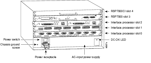
In a Cisco 7010 equipped with the RSP7000, access to the RSP7000 is from the rear. Slot 3, called the RSP 7000 slot 3, is reserved for the RSP7000 card. (See Figure 2.)
Figure 2 Cisco 7010 with RSP7000 and RSP7000CI Installed (Interface Processor End)
In a Cisco 7000 equipped with the RP, access to the RP is from the rear. (See Figure 3.) Slot 6, called the RP slot, is reserved for the RP card.
Figure 3 Cisco 7000 (Interface Processor End)
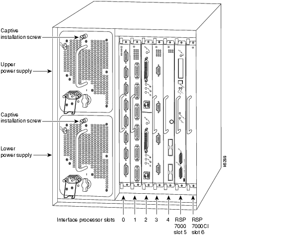
In a Cisco 7000 equipped with the RSP7000, access to the RSP7000 is from the rear. Slot 5, called the RSP 7000 slot 5, is reserved for the RSP7000 card. (See Figure 4.)
Figure 4 Cisco 7000 with RSP7000 and RSP7000CI Installed (Interface Processor End)
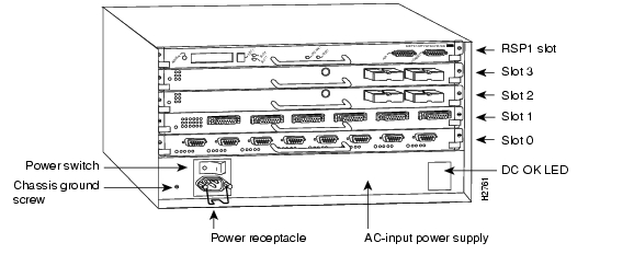
In a Cisco 7505, access to the RSP2 (or RSP1, RSP4, or RSP8) is from the rear. The top processor slot, called the RSP slot, is reserved for the RSP2 (or RSP1, RSP4, or RSP8) card. (See Figure 5.)
Figure 5 Cisco 7505 (Interface Processor End)
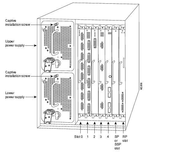
In a Cisco 7507 and Cisco 7507-MX, access to the RSP2, RSP4, or RSP8 is from the rear. Slots 2 and 3, called the RSP slots, are reserved for the RSP2, RSP4, or RSP8 cards. (See Figure 6.)
Figure 6 Cisco 7507 and Cisco 7507-MX (Interface Processor End)
In a Cisco 7513, Cisco 7513-MX, and Cisco 7576, access to the RSP2, RSP4, or RSP8 is from the rear. (See Figure 7.) Slots 6 and 7, called the RSP slots, are reserved for the RSP2, RSP4, or RSP8 cards.
Figure 7 Cisco 7513, Cisco 7513-MX, and Cisco 7576 (Interface Processor End)
Installing and Removing a Flash Memory Card (RSP and RSP7000 Only)
The RSP has two PC Card slots—slot 0 and slot 1—into which you can install a Flash memory card. (In the following procedure, the term RSP refers to the RSP1, RSP2, RSP4, RSP8, and RSP7000. Specific differences are noted.)
In the Cisco 7010 and Cisco 7505, the orientation of the RSP is horizontal. PC Card slot 0 is on the bottom, and PC Card slot 1 is on the top (see Figure 8).
In the Cisco 7000, Cisco 7507, Cisco 7507-MX, Cisco 7513, Cisco 7513-MX, or Cisco 7576, the orientation of the RSP is vertical. PC Card slot 0 is on the left, and PC Card slot 1 is on the right
(see Figure 9).In all RSPs, both PC Card slots can be used at the same time.
Note
Use the following procedure to install and remove a Flash memory card in an RSP or RSP7000. The procedure is generic and can be used for a Flash memory card in either PC Card slot position.
Step 1
Note
Step 2
Step 3
Step 4
Figure 8 Installing and Removing a Flash Memory Card (RSP1, RSP2, RSP4, or RSP8 in a Cisco 7505, or RSP7000 in a Cisco 7010)
Figure 9 Installing and Removing a Flash Memory Card (RSP2, RSP4, or RSP8 in a Cisco 7505, Cisco 7507, Cisco 7507-MX, Cisco 7513, Cisco 7513-MX,
or Cisco 7576, or RSP7000 in a Cisco 7000)
Formatting a Flash Memory Card (RSP and RSP7000 Only)
Before you can use a new Flash memory card, you must format it.
If you plan to use a Flash memory card that was formatted on another type of system, see the "Flash Memory Card Compatibility and Software Prerequisites" section, to determine if you need to reformat it first.
Caution
A Flash memory card that is shipped as part of a Cisco 7500 series system (or a Cisco 7000 or Cisco 7010 with an RSP7000) contains a Cisco IOS software image and does not require formatting to be used. A spare Flash memory card is shipped blank and must be formatted before use.
Note
Use the following procedure to format a new Flash memory card in an RSP or RSP7000 (the procedure assumes you have already booted your router).
Step 1
Step 2
Router# format slot0:All sectors will be erased, proceed? [confirm]Enter volume id (up to 30 characters): MyNewCardFormatting sector 1Format device slot0 completedRouter#
Note
The new Flash memory card is now formatted and ready to use.
Note
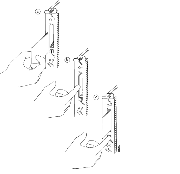
Installing and Removing a Flash Memory Card (RP Only)
The RP has one PC Card slot into which you can install a Flash memory card. (See Figure 11 and Figure 12.) The Flash memory card can be inserted and removed with the power on. All RP-specific cards must have a metal sleeve installed. This metal sleeve is shipped with all MEM-RP-FLC8M= and MEM-RP-FLC16M= (RP-specific) Flash memory cards. If you need a replacement metal sleeve, consult the Technical Assistance Center (TAC) as described on the last page of this document.
Use the following procedure to install and remove a Flash memory card in an RP:
Step 1
Figure 10 Installing the Metal Sleeve
Step 2
Note
Step 3
Step 4
Step 5
Figure 11 Installing and Removing a Flash Memory Card (RP in a Cisco 7000)
Figure 12 Installing and Removing a Flash Memory Card (RP in a Cisco 7010)
Formatting a Flash Memory Card (RP Only)
Before you can use a new Flash memory card, you must format it. Also, if you plan to boot from a Flash memory card that was formatted on an RSP-based system (Cisco 7500 series router or a Cisco 7000 series router with an RSP7000), you must first reformat the card on your system.
Note
Caution
Use the following procedure to format a new Flash memory card in an RP (the procedure assumes you have already booted your router).
Step 1
Step 2
Router# format slot0:All sectors will be erased, proceed? [confirm]Enter volume id (up to 30 characters): MyNewCardFormatting sector 1Format device slot0 completedRouter#
Note
The new Flash memory card is now formatted and ready to use.
Note
Copying an Image to a Flash Memory Card (RP, RSP, and RSP7000)
With the Flash memory card formatted, you can now copy an image to it. The following procedure assumes:
•
•
•
•
Use the following procedure to copy a file (called new.image) to a Flash memory card:
Step 1
Step 2
Step 3
Router> enPassword:Router# copy tftp:new.image slot0:new.image20575008 bytes available on device slot0, proceed? [confirm]Address or name of remote host [1.1.1.1]?Loading new.image from 1.1.1.1 (via Ethernet1/0):!!!!!!!!!!!!!!!!!!!!!!!!!!!!!!!!!!!!!!!!!!!!!!!!!!!!!!!!!!!!!!!!!!!!!!!!!!!!!!!!!!!!!!!!!!!!!!!!!!!!!!!!!!!!!!!!!!!!!!!!!!!!!!!!!!!!!!!!!!!!!!!!!!!!!!!!!!!!!!!!!!!!!!!!!!!!!!!!!!!!!!!!!!!!!!!!!!!!!!!!!!!!!!!!!!!!!!!!!!!!!!!!!!!!!!!!!!!!!!!!!!!!!!!!!!!!!!!!!!!!!!!!!!!!!!!!!!!!!!!!!!!!!!!!!!!!!!!!!!!!!!!!!!!!!!!!!!!!!!!!!!!!!!!!!!!!!!!!!!!!!!!!!!!!!!!!!!!!!!!!!!!!!!!!!!!!!!!!!!!!!!!!!!!!!!!!!!!!!!!!!!!!!!!!!!!!!!!!!!!!!!!!!!!!!!!!!!!!!!!!!!!!!!!!!!!!!!!!!!!!!!!!!!!!!!!!!!!![OK - 7799951/15599616 bytes]CCCCCCCCCCCCCCCCCCCCCCCCCCCCCCCCCCCCCCCCCCCCCCCCCCCCCCCCCCCCCCCCCCCCCCCCCCCCCCCCCCCCCCCCCCCCCCCCCCCCCCCCCCCCCCCCCCCCCCCCCCCCCCCCCCCCCCCCCCCCCCCCCCCCCCCCCCCCCCCCCCCCCCCCCCCCCCCCCCCCCCCCCCCCCCCCCCCCCCCCCCCCCCCCCCCCCCCCCCCCCCCCCCCCCCCCCCRouter#
Note
Making a Flash Memory Card Image Bootable (RP, RSP, and RSP7000)
After you copy an image to the Flash memory card, use the following series of commands to make the image (the file named new.image) bootable. Note that the config-register command is part of the sequence because the configuration register must be set to 0x2102 to enable loading an image from Flash memory.
Router# config terminalRouter(config)# no boot systemRouter(config)# boot system flash slot0:new.imageRouter(config)# config-register 0x2102Crtl-zRouter# copy running-config startup-configRouter# reloadWhen the system reloads it will boot the image new.image from the Flash memory card in slot 0.
Note
Copying Bootable Images Between Flash Memory Cards (RSP and RSP7000 only)
As future releases of Cisco IOS images become available, you will receive these images either as a file booted from a network server, a file on floppy disk, or a file on a Flash memory card.
The following scenario describes how to use a newly released image on a Flash memory card in a system that has an older image on a Flash memory card in slot 0 and a default boot image in the onboard Flash SIMM.
For this scenario, the filenames are as follows:
•
•
•
Copy the new image from the new Flash memory card to the Flash memory card that contains the old image.
Note
Use the following procedure to copy bootable images between Flash memory cards:
Step 1
Step 2
Router> enPassword:Router#Step 3
Step 4
Router# copy slot1:image.new slot0:image.new
Note
Step 5
Router# config tRouter(config)# no boot systemRouter(config)# boot system flash slot0:image.newCrtl-ZRouter# copy running-config startup-configRouter# reloadWhen the system reloads, it will boot the file image.new from the Flash memory card in slot 0.
Enabling Booting from Flash Memory (RSP and RSP7000 only)
To enable booting from Flash memory, set configuration register bits 3, 2, 1, and 0 to a value between 2 and 15 in conjunction with the boot system flash [filename] configuration command.
Following are definitions of the various Flash memory-related boot commands:
boot system flash—Boots the first file in onboard Flash memory
boot system flash:—Boots the first file in onboard Flash memory
boot system flash herfile—Boots the file named "herfile" on onboard Flash memory
boot system flash slot0:—Boots the first file on Flash memory card in slot 0
boot system flash flash:hisfile —Boots the first file named "hisfile" on onboard Flash memory
boot system flash slot0:myfile —Boots the file named "myfile" on the Flash memory card in slot 0
Enter configuration mode and specify a Flash memory filename in the PC Card slot from which to boot by using the configure terminal command, as follows:
Router# configure terminalEnter configuration commands, one per line. End with CTRL-Z.Router(config)# boot system flash slot0:myfileDisable Break and enable the boot system flash slot0: command using the config-register command. Use the value shown in the following example:
Router(config)# config-reg 0x2102To exit configuration mode, enter Ctrl-Z as follows:
Ctrl-zRouter#Save the new configuration to memory using the copy running-config startup-config command as follows:
Router# copy running-config startup-configWhen you enter boot commands, pay attention to the use of the Space key, which influences the way the router interprets the command. For example, notice the difference in the following commands: in the first case, the router boots the file specified (myfile); in the second case, the router finds the filename field blank and boots the first file on the Flash memory card.
Router(config)# boot system flash slot0:myfile (correct command)Router(config)# boot system flash slot0: myfile (incorrect command)Enabling Booting from Flash Memory (RP Only)
To enable booting from Flash memory, set configuration register bits 3, 2, 1, and 0 to a value between 2 and 15 in conjunction with the boot system flash [filename] configuration command.
Following are definitions of the various Flash memory-related boot commands:
boot system flash—Boots the first file in onboard Flash memory
boot system flash flash:—Boots the first file in onboard Flash memory
boot system flash herfile—Boots the file named "herfile" on onboard Flash memory
boot system flash slot0:—Boots the first file on Flash memory card in the PC Card slot (slot 0)
boot system flash flash:hisfile —Boots the first file named "hisfile" on onboard Flash memory
boot system flash slot0:myfile —Boots the file named "myfile" on the Flash memory card in the PC Card slot (slot 0)
To enter configuration mode and specify a Flash memory filename in the PC Card slot from which to boot, enter the configure terminal command at the enable prompt, as follows:
Router# configure terminalEnter configuration commands, one per line. End with CTRL-Z.Router(config)# boot system flash slot0:myfileTo disable Break and enable the boot system flash slot0: command, enter the config-register command with the value shown in the following example:
Router(config)# config-reg 0x2102To exit configuration mode, enter Ctrl-Z as follows:Ctrl-ZRouter#To save the new configuration to memory, use the copy running-config startup-config command as follows:
Router# copy running-config startup-configWhen you enter boot commands, pay attention to the use of the Spacebar key, which influences the way the router interprets the command. For example, notice the difference in the following commands: in the first case, the router boots the file specified (myfile); in the second case, the router finds the filename field blank and boots the first file on the Flash memory card.
Router(config)# boot system flash slot0:myfile (correct command)Router(config)# boot system flash slot0: myfile (incorrect command)Copying an Image to Flash Memory (RSP and RSP7000 Only)
You might need to copy an image to Flash memory whenever a new Cisco IOS software image or Cisco IOS software maintenance release becomes available.
Use the command copy tftp:filename [bootflash | slot0 | slot1]:filename for the copy procedure where tftp:filename is the source of the file, and [bootflash | slot0 | slot1]:filename is the destination in onboard Flash memory or on either of the two Flash memory cards in PC Card slot 0 or slot 1.
An example of the copy tftp:filename command follows for a file in the Flash memory card in PC Card slot 0:
Router# copy tftp:myfile1 slot0:myfile120575008 bytes available on device slot0, proceed? [confirm]Address or name of remote host [1.1.1.1]?Loading new.image from 1.1.1.1 (via Ethernet1/0):!!!!!!!!!!!!!!!!!!!!!!!!!!!!!!!!!!!!!!!!!!!!!!!!!!!!!!!!!!!!!!!!!!!!!!!!!!!!!!!!!!!!!!!!!!!!!!!!!!!!!!!!!!!!!!!!!!!!!!!!!!!!!!!!!!!!!!!!!!!!!!!!!!!!!!!!!!!!!!!!!!!!!!!!!!!!!!!!!!!!!!!!!!!!!!!!!!!!!!!!!!!!!!!!!!!!!!!!!!!!!!!!!!!!!!!!!!!!!!!!!!!!!!!!!!!!!!!!!!!!!!!!!!!!!!!!!!!!!!!!!!!!!!!!!!!!!!!!!!!!!!!!!!!!!!!!!!!!!!!!!!!!!!!!!!!!!!!!!!!!!!!!!!!!!!!!!!!!!!!!!!!!!!!!!!!!!!!!!!!!!!!!!!!!!!!!!!!!![OK - 7799951/15599616 bytes]CCCCCCCCCCCCCCCCCCCCCCCCCCCCCCCCCCCCCCCCCCCCCCCCCCCCCCCCCCCCCCCCCCCCCCCCCCCCCCCCCCCCCCCCCCCCCCCCCCCCCCCCCCCCCCCCCCCCCCCCCCCCCCCCCCCCCCCCCCCCCCCCCCCCCCCCCCCCCCCCCCCCCCCCCCCCCCCCCCCCCCCCCCCCCCCCCCCCCCCCCCCCCCCCCCCCCCCCCCCCCCCCCCCCCCCCCCRouter#
Note
Copying an Image to Flash Memory (RP Only)
You might need to copy an image to Flash memory whenever a new Cisco IOS software image or Cisco IOS software maintenance release becomes available.
Use the command copy tftp:filename [bootflash | slot0]:filename for the copy procedure where tftp:filename is the source of the file, and bootflash | slot0]:filename is the destination in onboard Flash memory or on either of the Flash memory cards.
An example of the copy tftp:filename command follows for a file in the Flash memory card in PC Card slot 0:
Router# copy tftp:myfile1 slot0:myfile120575008 bytes available on device slot0, proceed? [confirm]Address or name of remote host [1.1.1.1]?Loading new.image from 1.1.1.1 (via Ethernet1/0):!!!!!!!!!!!!!!!!!!!!!!!!!!!!!!!!!!!!!!!!!!!!!!!!!!!!!!!!!!!!!!!!!!!!!!!!!!!!!!!!!!!!!!!!!!!!!!!!!!!!!!!!!!!!!!!!!!!!!!!!!!!!!!!!!!!!!!!!!!!!!!!!!!!!!!!!!!!!!!!!!!!!!!!!!!!!!!!!!!!!!!!!!!!!!!!!!!!!!!!!!!!!!!!!!!!!!!!!!!!!!!!!!!!!!!!!!!!!!!!!!!!!!!!!!!!!!!!!!!!!!!!!!!!!!!!!!!!!!!!!!!!!!!!!!!!!!!!!!!!!!!!!!!!!!!!!!!!!!!!!!!!!!!!!!!!!!!!!!!!!!!!!!!!!!!!!!!!!!!!!!!!!!!!!!!!!!!!!!!!!!!!!!!!!!!!!!!!!![OK - 7799951/15599616 bytes]CCCCCCCCCCCCCCCCCCCCCCCCCCCCCCCCCCCCCCCCCCCCCCCCCCCCCCCCCCCCCCCCCCCCCCCCCCCCCCCCCCCCCCCCCCCCCCCCCCCCCCCCCCCCCCCCCCCCCCCCCCCCCCCCCCCCCCCCCCCCCCCCCCCCCCCCCCCCCCCCCCCCCCCCCCCCCCCCCCCCCCCCCCCCCCCCCCCCCCCCCCCCCCCCCCCCCCCCCCCCCCCCCCCCCCCCCCRouter#
Note
RSP-Specific Flash Memory Commands (RSP and RSP7000 Only)
This section provides additional commands related to the Flash memory in the single in-line memory module (SIMM) on the RSP or RSP7000 (called bootflash) and in PC Card cards. (The RP does not have an onboard bootflash device.) The following example assumes you have Flash memory cards in PC Card slots 0 and 1.
You can determine which PC Card slot you are accessing using the pwd command as follows:
Router# pwdslot0You can move between Flash memory media using the cd [bootflash | slot0 | slot1] command as follows:
Router# cd slot0slot0Router# cd slot1Router# pwdslot1You can list the directory of any Flash memory media using the dir [bootflash | slot0 | slot1] command as follows:
Router# dir-#- -length- -----date/time------ name1 4601977 May 19 1994 09:42:19 myfile16 679 May 19 1994 05:43:56 todays-config7 1 May 19 1994 09:54:53 fun1You can delete a file from any Flash memory media using the delete command as follows:
Router# delete slot0:fun1Router# dir-#- -length- -----date/time------ name1 4601977 May 19 1994 09:42:19 myfile16 679 May 19 1994 05:43:56 todays-configTo verify that the delete command was successful, use the dir/all/long command.
Note
The squeeze command permanently removes files, which are marked as deleted, and pushes all other undeleted files together to eliminate spaces between them.
Following is the syntax of the squeeze command:
Router# squeeze slot0:All deleted files will be removed, proceed? [confirm]Squeeze operation may take a while, proceed? [confirm]ebESZTo prevent loss of data due to sudden power loss, the "squeezed" data is temporarily saved to another location of Flash memory, which is specially used by the system.
In the preceding command display output, the character "e" means this special location has been erased (which must be performed before any write operation). The character "b" means that the data that is about to be written to this special location has been temporarily copied. The character "E" signifies that the sector that was temporarily occupied by the data has been erased. The character "S" signifies that the data was written to its permanent location in Flash memory.
The squeeze command operation keeps a log of which of these functions has been performed so in case of a sudden power failure, it can come back to the right place and continue with the process. The character "Z" means this log was erased after the successful squeeze command operation.
Recovering from Locked Blocks (RP, RSP, and RSP7000)
A locked block of Flash memory occurs when power is lost or a Flash memory card is unplugged during a write or erase operation. When a block of Flash memory is locked, it cannot be written to or erased, and the operation consistently fails at a particular block location. The only way to recover from locked blocks is by reformatting the Flash memory card with the format command. (For additional command descriptions and configuration information, refer to the appropriate configuration publications listed in the "Related Documentation" section.)
Caution
Obtaining Documentation
Cisco documentation and additional literature are available on Cisco.com. Cisco also provides several ways to obtain technical assistance and other technical resources. These sections explain how to obtain technical information from Cisco Systems.
Cisco.com
You can access the most current Cisco documentation at this URL:
http://www.cisco.com/univercd/home/home.htm
You can access the Cisco website at this URL:
You can access international Cisco websites at this URL:
http://www.cisco.com/public/countries_languages.shtml
Ordering Documentation
You can find instructions for ordering documentation at this URL:
http://www.cisco.com/univercd/cc/td/doc/es_inpck/pdi.htm
You can order Cisco documentation in these ways:
•
http://www.cisco.com/en/US/partner/ordering/index.shtml
•
Documentation Feedback
You can send comments about technical documentation to bug-doc@cisco.com.
You can submit comments by using the response card (if present) behind the front cover of your document or by writing to the following address:
Cisco Systems
Attn: Customer Document Ordering
170 West Tasman Drive
San Jose, CA 95134-9883We appreciate your comments.
Obtaining Technical Assistance
For all customers, partners, resellers, and distributors who hold valid Cisco service contracts, Cisco Technical Support provides 24-hour-a-day, award-winning technical assistance. The Cisco Technical Support Website on Cisco.com features extensive online support resources. In addition, Cisco Technical Assistance Center (TAC) engineers provide telephone support. If you do not hold a valid Cisco service contract, contact your reseller.
Cisco Technical Support Website
The Cisco Technical Support Website provides online documents and tools for troubleshooting and resolving technical issues with Cisco products and technologies. The website is available 24 hours a day, 365 days a year at this URL:
http://www.cisco.com/techsupport
Access to all tools on the Cisco Technical Support Website requires a Cisco.com user ID and password. If you have a valid service contract but do not have a user ID or password, you can register at this URL:
http://tools.cisco.com/RPF/register/register.do
Submitting a Service Request
Using the online TAC Service Request Tool is the fastest way to open S3 and S4 service requests. (S3 and S4 service requests are those in which your network is minimally impaired or for which you require product information.) After you describe your situation, the TAC Service Request Tool automatically provides recommended solutions. If your issue is not resolved using the recommended resources, your service request will be assigned to a Cisco TAC engineer. The TAC Service Request Tool is located at this URL:
http://www.cisco.com/techsupport/servicerequest
For S1 or S2 service requests or if you do not have Internet access, contact the Cisco TAC by telephone. (S1 or S2 service requests are those in which your production network is down or severely degraded.) Cisco TAC engineers are assigned immediately to S1 and S2 service requests to help keep your business operations running smoothly.
To open a service request by telephone, use one of the following numbers:
Asia-Pacific: +61 2 8446 7411 (Australia: 1 800 805 227)
EMEA: +32 2 704 55 55
USA: 1 800 553 2447For a complete list of Cisco TAC contacts, go to this URL:
http://www.cisco.com/techsupport/contacts
Definitions of Service Request Severity
To ensure that all service requests are reported in a standard format, Cisco has established severity definitions.
Severity 1 (S1)—Your network is "down," or there is a critical impact to your business operations. You and Cisco will commit all necessary resources around the clock to resolve the situation.
Severity 2 (S2)—Operation of an existing network is severely degraded, or significant aspects of your business operation are negatively affected by inadequate performance of Cisco products. You and Cisco will commit full-time resources during normal business hours to resolve the situation.
Severity 3 (S3)—Operational performance of your network is impaired, but most business operations remain functional. You and Cisco will commit resources during normal business hours to restore service to satisfactory levels.
Severity 4 (S4)—You require information or assistance with Cisco product capabilities, installation, or configuration. There is little or no effect on your business operations.
Obtaining Additional Publications and Information
Information about Cisco products, technologies, and network solutions is available from various online and printed sources.
•
http://www.cisco.com/go/marketplace/
•
http://cisco.com/univercd/cc/td/doc/pcat/
•
•
•
http://www.cisco.com/go/iqmagazine
•
•
http://www.cisco.com/en/US/learning/index.html
This document is to be used in conjunction with the documents listed in the "Related Documentation" section.
Copyright © 2004 Cisco Systems, Inc. All rights reserved.
![]()
![]()
![]()
![]()
![]()
![]()
![]()
![]()
Posted: Mon Aug 23 16:43:42 PDT 2004
All contents are Copyright © 1992--2004 Cisco Systems, Inc. All rights reserved.
Important Notices and Privacy Statement.