|
|

To continue your 6T3 line card installation, you must configure the serial interfaces.
This chapter contains the following sections:
You modify the configuration of your router through the software command interpreter called the EXEC (also called enable mode). You must enter the privileged level of the EXEC command interpreter with the enable command before you can use the configure command to configure a new interface or change the existing configuration of an interface. The system prompts you for a password if one has been set.
The system prompt for the privileged level ends with a pound sign (#) instead of an angle bracket (>). At the console terminal, use the following procedure to enter the privileged level:
Step 2 Enter the password (the password is case sensitive). For security purposes, the password is not displayed.
When you enter the correct password, the system displays the privileged-level system prompt (#):
To configure the new interfaces, proceed to the "Configuring the Interfaces" section.
After you verify that the new 6T3 line card is installed correctly (the STATUS LED goes on), use the privileged-level configure command to configure the new interfaces. Have the following information available:
If you installed a new 6T3 line card or if you want to change the configuration of an existing interface, you must enter configuration mode to configure the new interfaces. If you replaced a 6T3 line card that was previously configured, the system recognizes the new interfaces and brings each of them up in their existing configuration.
For a summary of the configuration options available and instructions for configuring interfaces on a 6T3 line card, refer to the appropriate configuration publications listed in the "Related Documentation" section.
You execute configuration commands from the privileged level of the EXEC command interpreter, which usually requires password access. Contact your system administrator, if necessary, to obtain password access. (See the "Using the EXEC Command Interpreter" section for an explanation of the privileged level of the EXEC.)
This section contains the following subsections:
Before you remove an interface that you will not replace, or replace line cards, use the shutdown command to shut down (disable) the interfaces to prevent anomalies when you reinstall the new or reconfigured interface processor. When you shut down an interface, it is designated administratively down in the show command displays.
Follow these steps to shut down an interface:
Step 2 At the privileged-level prompt, enter configuration mode and specify that the console terminal is the source of the configuration subcommands, as follows:
Step 3 Shut down interfaces by entering the interface serial subcommand (followed by the interface address of the interface), and then enter the shutdown command. Table 4-1 shows the command syntax.
When you have finished, press Ctrl-Z—hold down the Control key while you press Z—or enter end or exit to exit configuration mode and return to the EXEC command interpreter.
Table 4-1 Syntax of the shutdown Command
| Platform | Command | Example |
|---|---|---|
interface, followed by the type (serial) and slot/port (slot-number/ |
The example is for interface 0 and interface 1 on a 6T3 line card in slot 2. |
 |
Note If you need to shut down additional interfaces, enter the interface serial command (followed by the interface address of the interface) for each of the interfaces on your line card. Use the no shutdown command to enable the interface. |
Step 4 Write the new configuration to NVRAM as follows:
The system displays an OK message when the configuration has been stored in NVRAM.
Step 5 Verify that new interfaces are now in the correct state (shut down) using the
show interfaces command (followed by the interface type and interface address of the interface) to display the specific interface. Table 4-2 provides examples.
Table 4-2 Examples of the show interfaces serial Command
| Platform | Command | Example |
|---|---|---|
show interfaces serial, followed by slot/port (slot-number/ |
The example is for interface 0 on a 6T3 line card in slot 2. |
Step 6 Reenable interfaces by doing the following:
a. Repeat Step 3 to reenable an interface. Substitute the no shutdown command for the shutdown command.
b. Repeat Step 4 to write the new configuration to memory.
Use the copy running-config startup-config command.
c. Repeat Step 5 to verify that the interfaces are in the correct state. Use the
show interfaces command followed by the interface type and interface address of the interface.
For complete descriptions of software configuration commands, refer to the publications listed in the "Related Documentation" section.
Following are instructions for a basic configuration: enabling an interface and specifying IP routing. You might also need to enter other configuration subcommands, depending on the requirements for your system configuration and the protocols you plan to route on the interface. For complete descriptions of configuration subcommands and the configuration options available for serial interfaces, refer to the appropriate software documentation.
In the following procedure, press the Return key after each step unless otherwise noted. At any time you can exit the privileged level and return to the user level by entering disable at the prompt as follows:
Step 2 Specify the first interface to configure by entering the interface serial subcommand, followed by the interface address of the interface you plan to configure. Table 4-3 provides an example.
Table 4-3 Examples of the interface serial Subcommand
| Platform | Command | Example |
|---|---|---|
interface serial, followed by slot/port (slot-number/ |
The example is for the first interface of a |
Step 3 Assign an IP address and subnet mask to the interface (if IP routing is enabled on the system) by using the ip address subcommand, as in the following example:
Step 4 Add any additional configuration subcommands required to enable routing protocols and set the interface characteristics.
Step 5 Reenable the interfaces using the no shutdown command. (See the "Shutting Down an Interface" section.)
Step 6 Configure all additional line card interfaces as required.
Step 7 After including all of the configuration subcommands to complete your configuration, press Ctrl-Z—hold down the Control key while you press Z—or enter end or exit to exit configuration mode and return to the EXEC command interpreter prompt.
Step 8 Write the new configuration to NVRAM as follows
This completes the procedure for creating a basic configuration.
Table 4-4 shows the default values for the 6T3 line card serial interfaces.
Table 4-4 6T3 Line Card Serial Interface Default Values
| Parameter | Configuration Command | Default Value |
|---|---|---|
[no] dsu mode [adtran | cisco | digital-link | kentrox| larscom] |
||
[no] loopback [local | network line | network payload | remote | dte] |
||
There are two sides to the network, a local network side and a remote customer side, or near and far ends. The 6T3 line card supports third-party data service units (DSUs), Internet Service Provider (ISP)-provided DS3 lines, and so on. You can change the configuration parameter default values in the 6T3 line card port interfaces to match the remote DSUs on your network. Table 4-5 shows the configuration parameters.
Table 4-5 6T3 Line Card Serial Interface DSU Modes
| Parameter | Configuration Command | Default Value | Command |
|---|---|---|---|
[no] dsu mode [adtran | cisco | digital-link | kentrox| larscom] |
|||
| 1Adtran DSU mode does not support payload scrambling. |
|
Note The local port and the remote port must have matching configuration. |
You can use telnet to determine the DSU mode settings on the remote DS3 port. Once you verify the remote DS3 port settings, you can negotiate changing configuration parameters so that DSU mode settings are the same on both the local and remote DS3 ports. You can set the DSU bandwidth to accept or reject the incoming remote requests from the local DS3 port by entering the dsu remote accept interface configuration command.
The DSU mode supports several third-party DSU vendors—Adtran, Digital Link, Kentrox, and Larscom—and the default DSU mode, Cisco. If you use a DSU to make the connection between the Cisco 7304 router and another device, the local DS3 port configuration must match the remote DS3 port configuration. Therefore, if the remote DS3 port uses the Kentrox vendor, a request is sent to the local DS3 port to change the DSU mode to Kentrox, either by manually entering the dsu mode configuration command and specifying the Kentrox DSU or by using the Cisco Remote Connection Management (CRCM) feature to remotely configure the remote DS3 port. If you make a direct connection between a Cisco 7304 router and another device, you can use the Cisco DSU mode.
The local and remote DS3 ports must also agree on whether to use a subrate or fullrate sending and receiving rate, because the speed of the sending and receiving rate is regulated by the DSU mode. If the sending and receiving rates do not match, they will not work. Subrates are specific to DSU modes and must be configured appropriately. The subrate sending and receiving rate is slower and less expensive than the faster, more expensive, fullrate. You can synchronize the local and remote DS3 ports sending and receiving rates by entering the dsu remote interface configuration command.
The DSU bandwidth range is from 0 to 44210 kbps. The local port and the remote port must have matching configuration. Therefore, if you reduce the effective bandwidth to 3000 on the local port, you must do the same on the remote port by entering the dsu bandwidth interface configuration command.
In interface configuration mode, reduce effective bandwidth (range of 0 to 44210 kbps) by entering the dsu bandwidth configuration subcommand, as in the following example:
Use the no form of this command to return to the default, 44210.
|
Note The local port configuration must match the remote port configuration. |
Payload (data) scrambling converts the data received by the local or remote DS3 ports from the Digital Link, Kentrox, and Larscom third-party DSU vendor modes as well as the default, Cisco mode. The Adtran DSU mode does not support payload scrambling.
To enable payload scrambling on the local and remote DS3 ports, you must enter the scramble interface configuration command. If you do not enter the scramble command, payload scrambling remains disabled by default on the local and remote DS3 ports.
Table 4-6 summarizes cyclic redundancy check (CRC) commands. For more information, see the remainder of this section.
| Purpose | Command | Example | Further Information |
|---|---|---|---|
The example disables 32-bit CRC on a serial interface and returns to the default 16-bit CRC: |
CRC is an error-checking technique that uses a calculated numeric value to detect errors in transmitted data. All interfaces use a 16-bit CRC (CRC-CITT) by default but also support a 32-bit CRC. The sender of a data frame calculates the frame check sequence (FCS). Before it sends a frame, the sender appends the FCS value to the message. The receiver recalculates the FCS and compares its calculation to the FCS from the sender. If there is a difference between the two calculations, the receiver assumes that a transmission error occurred and sends a request to the sender to resend the frame.
Enable 32-bit CRC using the crc 32 command. Before you can enable 32-bit CRC, you must use the interface serial command (followed by the interface address of the interface) to select the interface on which you want to enable 32-bit CRC. This command functions in the same way on all supported platforms.
In the example that follows, 32-bit CRC is specified:
The preceding command example applies to all systems in which the 6T3 line card is supported.
Use the no crc 32 command to disable CRC-32 and return the interface to the default CRC-16 (CRC-CITT) setting.
When you have finished, press Ctrl-Z—hold down the Control key while you press Z—or enter end or exit to exit configuration mode and return to the EXEC command interpreter prompt. Then write the new configuration to NVRAM using the copy running-config startup-config command.
|
Note When enabling a 16-bit or 32-bit CRC on a local interface, ensure that the remote device is also configured for a 16-bit or 32-bit CRC. |
For command descriptions, refer to the Configuration Fundamentals Configuration Guide publication. For more information, see the "Obtaining Documentation" section and the "Obtaining Technical Assistance" section.
The only exception for matching local and remote DS3 port configurations is that the clock sources must be set opposite each other. Therefore, if you enter the clock source internal command for the local DS3 port, you must enter clock source line for the remote DS3 port.
In interface configuration mode, define the DSU interoperability mode by entering the dsu mode [adtran | [cisco | digital-link | kentrox | larscom ] configuration subcommand, as in the following example:
Use the no form of this command to return to the default, 0.
|
Note The local port configuration must match the remote port configuration. For example, if you define the DSU interoperability mode as cisco on the local port, you must do the same on the remote port. You need to know what type of DSU is at the remote port to find out if it interoperates with the 6T3 line card. For T3 serial interfaces, specify cisco for connection from a 6T3 line card to another 6T3 line card. Specify adtran for connection from a 6T3 line card to an Adtran DSU. Specify digital-link for connection to a Digital Link DSU (DL3100). Specify kentrox for connection from a 6T3 line card to a Kentrox DSU. Specify larscom for connection from a 6T3 line card to a Larscom DSU. |
Also see the "Interoperability Guidelines for 6T3 Line Card DSUs" section for information regarding DSU feature compatibilities.
In interface configuration mode, enable T3 scrambling by entering the scramble configuration subcommand, as in the following example:
Use the no form of this command to restore the default value, disabled.
|
Note The local port configuration must match the remote port configuration. For example, if you enable scrambling on the local port, you must do the same on the remote port. |
Also see the "Interoperability Guidelines for 6T3 Line Card DSUs" section for information regarding DSU feature compatibilities.
In interface configuration mode, specify T3 framing by entering the framing {c-bit | m23} configuration subcommand, as in the following example:
Use the no form of this command to return to the default, C-bit framing.
In interface configuration mode, set the cable length (0 to 450 feet), as in the following example:
Use the no form of this command to return to the default, which is 50 feet.
After configuring the new interface, use the show commands to display the status of the new interface or all interfaces, and use the ping and loopback commands to check connectivity. This section includes the following subsections:
Table 4-7 demonstrates how you can use the show commands to verify that new interfaces are configured and operating correctly and that the 6T3 line card appears in them correctly. Sample displays of the output of selected show commands appear in the sections that follow. For complete command descriptions and examples, refer to the publications listed in the "Related Documentation" section.
|
Note The outputs that appear in this document may not match the output you receive when running these commands. The outputs in this document are examples only. |
If an interface is shut down and you configured it as up, or if the displays indicate that the hardware is not functioning properly, ensure that the interface is properly connected and terminated. If you still have problems bringing up the interface, contact a service representative for assistance. This section includes the following subsections:
Choose the subsection appropriate for your system. Proceed to the "Using the ping Command to Verify Network Connectivity" section when you have finished using the show commands.
Display the configuration of the system hardware, the number of each interface type installed, the Cisco IOS software version, the names and sources of configuration files, and the boot images by using the show version (or show hardware) command.
|
Note The outputs that appear in this document may not match the output you receive when running these commands. The outputs in this document are examples only. |
Following is an example of the show version command from a Cisco 7304 router with the 6T3 line card:
Display the types of line cards installed in your system (and specific information about each) using the show diag slot command.
|
Note The outputs that appear in this document may not match the output you receive when running these commands. The outputs in this document are examples only. |
Following is an example of the show diag slot command that shows the 6T3 line card in slot 5 of a Cisco 7304 router:
The show interfaces command displays status information (including the physical slot and interface address) for the interfaces you specify. The example that follows specifies serial interfaces.
|
Note The outputs that appear in this document may not match the output you receive when running these commands. The outputs in this document are examples only. |
Following is an example of the show interfaces command for Cisco 7304 routers. In this example, the serial interfaces (0 to 5) are on a 6T3 line card in slot 5; also, the status information for interfaces 1 through 5 is omitted. (Interfaces are administratively shut down until you enable them.)
This section assumes that you are familiar with DS3 alarms and line states. The 6T3 line card does not have an LED for alarm and event detection. However, you can enter the show controllers serial slot/port EXEC command to verify whether the alarm and event detection messages are active or inactive. Most alarm and event detection messages are short-lived, because if problems occur, the line card clears the error condition, but records the event to verify line card operation status.
The output from the show controllers serial slot/port EXEC command sends messages about the following types of alarms and events:
The output also indicates whether the alarm or event originates from the local end connector or the remote end connector, as shown in the following example:
Using the ping command, you can verify that an interface port is functioning properly. This section provides a brief description of this command. Refer to the publications listed in the "Related Documentation" section for detailed command descriptions and examples.
The ping command sends echo request packets out to a remote device at an IP address that you specify. After sending an echo request, the system waits a specified time for the remote device to reply. Each echo reply is displayed as an exclamation point (!) on the console terminal; each request that is not returned before the specified timeout is displayed as a period (.). A series of exclamation points (!!!!!) indicates a good connection; a series of periods (.....) or the messages [timed out] or [failed] indicate a bad connection.
Following is an example of a successful ping command to a remote server with the address 10.0.0.10:
If the connection fails, verify that you have the correct IP address for the destination and that the device is active (powered on), and repeat the ping command.
Proceed to the next section, "Using loopback Commands ," to finish checking network connectivity.
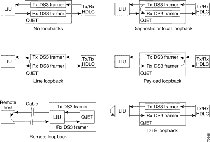
With the loopback test, you can detect and isolate equipment malfunctions by testing the connection between the 6T3 line card interface and a remote device such as a modem or a CSU/DSU. The loopback command places an interface in loopback mode, which enables test packets that are generated from the ping command to loop through a remote device or compact serial cable. If the packets complete the loop, the connection is good. If not, you can isolate a fault to the remote device or compact serial cable in the path of the loopback test.
Table 4-8 provides examples of the loopback {dte | local | network {line | payload} | remote} command. The examples given are for interface 0 of a 6T3 line card in slot 2 of a Cisco 7304 router:
Table 4-8 Using loopback Commands
| 1Remote loopback mode works with C-bit framing only. The other loopback modes listed above work with C-bit and M23 framing. Refer to the "Specifying T3 Framing" section for information on configuring C-bit framing. |
Figure 4-1 shows the data flow for three loopback configuration paths, including no loopback.
The ratio of received bits on an interface that contain errors is called the bit error rate (BER). A bit error rate test (BERT) is used to check the BER. T3 bit error rate testing is used on the Cisco 7304 router to check communication between local and remote DS3 ports. If traffic is not being transmitted or received on a DS3 port, or if the quality of the line simply needs to be tested, T3 bit error rate testing can be used to test the port.
For information on performing bit error rate testing, refer to T3 Bit Error Rate Testing on the Cisco 7304 Router.
Line cards can be removed from the Cisco 7304 router without disrupting data flow by using the hw-module slot slot # stop/start command in EXEC mode. The hw-module slot slot # stop command will stop traffic, shut down all line card interfaces, and deactivate the line card. The hw-module slot slot # start command resets the line card, puts the line card back online and turns off the OIR LED.
|
Note Upon insertion of a line card, the system will automatically activate the card. The hw-module slot slot # start command is only necessary when reactivating an installed line card that has been deactivated with the hw-module slot slot # stop command. |
To remove and install an active line card in slot 2 proceed as follows:
When the OIR LED turns green, the line card in slot 2 has been deactivated and can be physically removed and replaced with a new line card (see the "Line Card Removal and Installation" section.)
When the new line card is inserted in slot 2 it is automatically reset, put online, and the OIR LED is turned off.
The 6T3 line card automatically recovers from the following catastrophic errors:
If the 6T3 line card encounters more than five fatal errors within one hour, recovery will not be attempted and the line card will be deactivated. To reactivate the line card use the hw-module slot slot # start command, or physically remove and replace the line card.
The 6T3 line card crash history may be viewed by using the show diag slot command. The crash history is saved as long as the line card is physically present in the chassis. Physically removing the 6T3 line card from the chassis or performing a CLI-controlled OIR will clear the crash history.
The following messages are associated with line card recovery:
Error Message 00:00:06:% LC-3-RECOVERY: Line card (slot <x>) recovery in progress
Error Message 00:00:06:% LC-3-EXCESSERRORS: Noof errors seen on the line card
(slot <x>) exceed the threshold
When the 6T3 line card encounters any of the non-recoverable errors listed below, the line card is deactivated and must be restarted by performing a CLI-controlled OIR or physically removing and installing the line card.
The following examples show non recoverable fatal error messages:
Error Message 00:00:06% SERIAL-0-DLL_OUTOFLOCK: T3 HW DLLS failed to lock in line
card at slot <x>
Error Message 00:00:06% SERIAL-0-860_BOOT_NOTOK: T3 Line card local processor at
slot <x> failed to boot
Error Message 00:00:06% SERIAL-3-FW_CHECKSUM_FAILED: T3 line card in slot <x>,
firmware integrity check failed (section <x>, expected checksum: <x>, calculated
checksum: <x>)
Error Message 00:00:06% ENVM-0-SHUTDOWN: Environmental Monitor initiated shutdown
due to <voltage/temperature/power supply> in slot <x>
Error Message 00:00:06% SERIAL-1-ALLOCFAIL: T3 (slot <x>) line card plugin structure
allocation failure
![]()
![]()
![]()
![]()
![]()
![]()
![]()
![]()
Posted: Tue Jun 10 13:47:08 PDT 2003
All contents are Copyright © 1992--2003 Cisco Systems, Inc. All rights reserved.
Important Notices and Privacy Statement.