|
|

Table Of Contents
Removing and Installing the OC-12 ATM Line Card
Line Card Removal and Installation
SFP Module Removal and Installation
Removing and Installing the OC-12 ATM Line Card
This chapter describes how to remove the OC-12 ATM line card from its supported platform, how to install a new or replacement line card, and how to install SFP modules.
This chapter contains the following sections:
•
Online Insertion and Removal
•
•
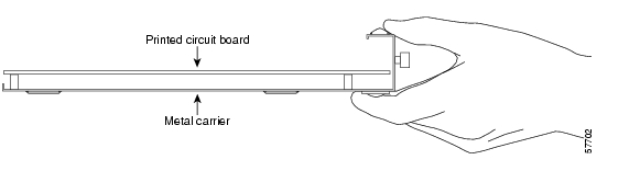
Handling Line Cards
Each line card circuit board is mounted to a metal carrier and is sensitive to electrostatic discharge (ESD) damage.
Caution
Figure 3-1 Handling a Line Card
Online Insertion and Removal
The Cisco 7304 router supports online insertion and removal (OIR) of line cards; you do not have to power down the router when removing and replacing an OC-12 ATM on a Cisco 7304 router. The Cisco 7304 router also supports CLI-controlled OIR (see the "CLI-Controlled OIR" section on page 4-32), which allows for the completion of data traffic before the active interfaces are shut down.
Note
Note
Warnings and Cautions
Observe the following warnings and cautions when installing or removing line cards.
Warning
Warning
Warning
Warning
Caution
Caution
Line Card Removal and Installation
This section describes how to remove and install the OC-12 ATM in the Cisco 7304 router.
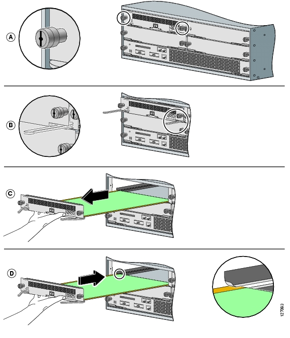
Removing the Line Card
To remove the line card, refer to Figure 3-2 and do the following:
Step 1
Step 2
Step 3
Step 4
Step 5
Installing the Line Card
To install the line card, refer to Figure 3-2 and do the following:
Step 1
Step 2
Note
Step 3
Step 4
Note
Step 5
Note
Figure 3-2 Line Card Removal and Installation
SFP Module Removal and Installation
The OC-12 ATM line card only accepts the SFP modules listed as supported in this document. An SFP module check is run each time an SFP module is inserted into the OC-12 ATM line card and only SFP modules that pass this check are usable by the OC-12 ATM line card.
Note
The SFP modules support online insertion and removal (OIR). However, if the line card is already installed in the router and the system is operational, we recommend that you administratively shut down the SFP module port before installing a new SFP module.
Available Cisco SFP modules include the following:
•
•
•
•
•
Handling the SFP Module
Before handling the SFP module, observe the following guidelines:
•
•
Note
Removing the SFP Module
The following procedure describes removing the SFP module from a vertically or horizontally oriented card slot.
Warning
Caution
To remove the SFP module, perform the following steps:
Step 1
Step 2
Step 3
a.
b.
Note
c.
Step 4
Installing the SFP Module
Use the following procedure to install the SFP module:
Step 1
Step 2
Step 3
Step 4
Step 5
Figure 3-3 Inserting an SFP Module
Cabling the SFP Module
To continue your OC-12 ATM line card installation, you must connect the interface cables.
Step 1
Step 2
Note
Warning
![]()
![]()
![]()
![]()
![]()
![]()
![]()
![]()
Posted: Tue Mar 1 11:05:45 PST 2005
All contents are Copyright © 1992--2005 Cisco Systems, Inc. All rights reserved.
Important Notices and Privacy Statement.