|
|

Table Of Contents
Asynchronous Transfer Mode Overview
Fiber-Optic Transmission Specifications
Approximating the OC3 ATM Line Card Power Margin
Multimode Power Budget Example with Sufficient Power for Transmission
Multimode Power Budget Example of Dispersion Limit
SONET Single-Mode Power Budget Example
Using Statistics to Estimate Link Loss and Power Budget
Slot Locations on the Cisco 7304 Router
Cisco 7304 Router Slot Numbering
Identifying Interface Addresses
Cisco 7304 Router Interface Addresses
Overview
This chapter describes the OC3 ATM line cards and contains the following sections:
•
Asynchronous Transfer Mode Overview
•
•
•
•
•
•
•
Line Card Overview
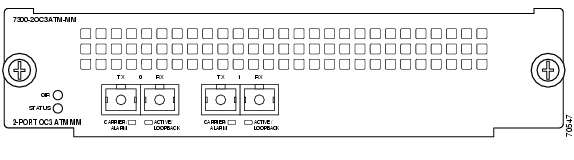
The OC3 ATM line card provides the Cisco 7304 router with two OC-3 (155.52-Mbps) ATM interfaces on a single card. You must use the appropriate optical fiber cables to connect the OC3 ATM line card with an external OC-3 network. (See the "Fiber-Optic Transmission Specifications" section and the "Cables and Connectors" section for more information on optical fiber cables.)
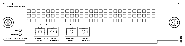
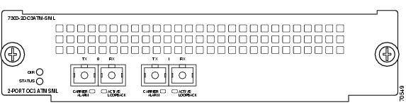
Three models of the OC3 ATM line card are available:
•
•
•
Figure 1-1 7300-2OC3ATM-MM—Faceplate View
Figure 1-2 7300-2OC3ATM-SMI—Faceplate View
Figure 1-3 7300-2OC3ATM-SML—Faceplate View
SONET/SDH Overview
SONET is an American National Standards Institute (ANSI) standard (T1.1051988) for optical digital transmission at hierarchical rates from 51.840 Mbps (STS-1) to 622.080 Mbps (STS-12) and greater. SDH is the international standard for optical digital transmission at hierarchical rates from 155.520 Mbps (STM-1) to 2.488 Gbps (STM-16) and greater.
SONET is an octet-synchronous multiplex scheme that defines a family of standard rates and formats. The available information bandwidth is 149.760 Mbps, which is the STS-3c/STM-1 Synchronous Payload Envelope (SPE), the payload portion of the SONET frame into which the octet-oriented user data is mapped. (Octet boundaries are aligned with the SPE octet boundaries.)
The International Telecommunication Union Telecommunication Standardization Sector (ITU-T) defines a series of SDH transmission rates beginning at 155.520 Mbps as follows:
STS-3c2
STM-1
STS-12c
STM-4c
STS-48c
STM-16c
1 ANSI-defined SONET specifications.
2 Currently supported by the OC3 ATM line card.
Despite the name, SONET is not limited to optical links. Electrical specifications have been defined for CATV 75-ohm coaxial cable. Transmission rates are integer multiples of 51.840 Mbps, which can be used to carry T3/E3 bit-synchronous signals.
The following transmission multiples are currently specified and commonly used:
•
•
•
Asynchronous Transfer Mode Overview
Asynchronous Transfer Mode (ATM) uses cell-switching and multiplexing technology that combines the benefits of circuit switching (constant transmission delay and guaranteed capacity) with those of packet switching (flexibility and efficiency for intermittent traffic).
ATM is a connection-oriented environment. All traffic to or from an ATM network is prefaced with a virtual path identifier (VPI) and virtual channel identifier (VCI). A VPI/VCI pair is considered a single virtual circuit (VC). Each VC is a private connection to another node on the ATM network. It is treated as a point-to-point mechanism to another router or host and is capable of supporting bidirectional traffic.
Each ATM node is required to establish a separate connection to every other node in the ATM network with which it must communicate. All such connections are established using a permanent virtual circuit (PVC) or a switched virtual circuit (SVC) with an ATM signaling mechanism. This signaling is based on the ATM Forum User-Network Interface (UNI) Specification V3.0.
Each VC is considered a complete and separate link to a destination node. Users can encapsulate data across the connection as they see fit. The ATM network disregards the contents of the data. The only requirement is that data be sent to the OC3 ATM card in the specific ATM adaptation layer (AAL) format.
An AAL defines the conversion of user information into cells. The AAL segments upper-layer information into cells at the transmitter and reassembles them at the receiver. ATM adaptation layer 5 (AAL5), one of four AALs recommended by the International Telecommunication Union Telecommunication Standardization Sector, supports data communications.
An ATM connection transfers raw bits of information to a destination router or host. The ATM router takes the common part convergence sublayer (CPCS) frame, carves it up into 53-byte cells, and sends these cells to the destination router or host for reassembly. 48 bytes of each cell are used for the CPCS data; the remaining 5 bytes are used for cell routing. The 5-byte cell header contains the destination VPI/VCI, payload type, cell loss priority (CLP), and header error control.
Unlike a LAN, which is connection less, ATM requires certain features to provide a LAN environment to the users. One such feature is broadcast capability. Protocols wanting to broadcast packets to all stations in a subnet must be allowed to do so with a single call to Layer 2. In order to support broadcasting, the router allows you to specify a particular VC as a broadcast VC. When the protocol passes a packet with a broadcast address to the ATM driver, the packet is duplicated and sent to each VC marked as a broadcast VC. This method is known as pseudobroadcasting.
Features
The OC3 ATM line card has the following features:
•
Note
•
•
•
•
•
•
•
•
•
•
•
•
•
•
•
•
The OC3 ATM line card supports the following protocols, services, and ATM-specific software:
•
•
•
•
•
Interface Specifications
The physical layer interface for the OC3 ATM line card is Optical Carrier-3 (OC-3c, the specification for SONET STS-3c and SDH STM-1 transmission rates). The OC3 ATM line card provides a single 155.520-Mbps Packet OC-3 network interface for all supported platforms.
Each OC3 ATM line card has one pair of SC-type fiber receptacles to allow connection to single-mode optical fiber. (For more information on the optical fiber cables you should use with this line card, see the "Fiber-Optic Transmission Specifications" section and the "Cables and Connectors" section.)
Packet data is transported using Point-to-Point Protocol (PPP) and is mapped into the STS-3c/STM-1 frame. (RFC-1619)
The management of the OC3 ATM line card interface is compliant with RFC 1595.
Fiber-Optic Transmission Specifications
This section describes the SONET specifications for fiber-optic transmissions, defines the power budget, and helps you approximate the power margin for multimode and single-mode transmissions. This section includes the following subsections:
•
•
•
•
SONET Distance Limitations
The SONET specification for fiber-optic transmission defines two types of fiber: single mode and multimode. Modes can be thought of as bundles of light rays entering the fiber at a particular angle. Single-mode fiber allows only one mode of light to propagate through the fiber, whereas multimode fiber allows multiple modes of light to propagate through the fiber. Because multiple modes of light propagating through the fiber travel different distances depending on the entry angles, causing them to arrive at the destination at different times (a phenomenon called modal dispersion), single-mode fiber is capable of higher bandwidth and greater cable run distances than multimode fiber.
The typical maximum distances for single-mode and multimode transmissions, as defined by SONET, are in Table 1-1.
Note
Table 1-1 lists the OC-3 optical parameters.
Table 1-1 OC-3 Optical Parameters
Type1
Power
to Receiver2
Budgets
Between StationsSingle-mode3
long reach-5 dBm min.
to 0 dBm max.
at 1280-1335 nm4-10 dBm
-34 dBm
10 to 28 dB
Up to 25 mi. (40 km)
Single-mode5 intermediate reach
-15 dBm min.
to -8 dBm max.
at 1280-1335 nm 4-8 dBm
-31 dBm
0 to 12 dB
Up to 9 mi. (15 km)
Multimode6
short reach-20 dBm min.
to -14 dBm max.
at 1280-1335 nm 4-8 dBm
-30 dBm
0 to 7 dB
Up to 1.2 mi. (2 km)
1 This table gives nominal OC-3 optical parameters.
2 This value represents the maximum power to which any receiver can be exposed.
3 Complies with Bellcore GR-253-CORE Long Reach Specification (LR-1).
4 Nominal wavelength is 1310 nm.
5 Complies with Bellcore GR-253-CORE Intermediate Reach Specification (IR-1).
6 Complies with Short-Reach OC-3 Specification SR-OC-3.
To calculate link losses and dispersion losses for your application, refer to the following specifications and documents:
•
•
•
•
Power Budget
To design an efficient optical data link, evaluate the power budget. The power budget is the amount of light available to overcome attenuation in the optical link and to exceed the minimum power that the receiver requires to operate within its specifications. Proper operation of an optical data link depends on modulated light reaching the receiver with enough power to be correctly demodulated.
Attenuation, caused by the passive media components (cables, cable splices, and connectors), is common to both multimode and single-mode transmission.
The following variables reduce the power of the signal (light) transmitted to the receiver in multimode transmission:
•
•
Attenuation is significantly lower for optical fiber than for other media. For multimode transmission, chromatic dispersion and modal dispersion reduce the available power of the system by the combined dispersion penalty. The power lost over the data link is the sum of the component, dispersion, and modal losses.
Table 1-2 lists the factors of attenuation and dispersion for typical optical fiber cable.
Table 1-2 Typical Fiber-Optic Link Attenuation and Dispersion Limits
Attenuation
0.5 dB/km
1.0 dB/km
Dispersion
No limit
500 MHz/km1
1 The product of bandwidth and distance must be less than 500 MHz/km.
Approximating the OC3 ATM Line Card Power Margin
The LED used for a multimode transmission light source creates multiple propagation paths of light, each with a different path length and time requirement to cross the optical fiber, causing signal dispersion (smear). Higher-order mode loss (HOL) results from light from the LED entering the fiber and being radiated into the fiber cladding. A worst-case estimate of power margin (PM) for multimode transmissions assumes minimum transmitter power (PT), maximum link loss (LL), and minimum receiver sensitivity (PR). The worst-case analysis provides a margin of error; not all of the parts of an actual system will operate at the worst-case levels.
The power budget (PB) is the maximum possible amount of power transmitted. The following equation lists the calculation of the power budget:
PB = PT - PR
PB = -20 dBm - (-30 dBm)
PB = 10 dBm
The power margin (PM) calculation is derived from the power budget minus the link loss, as follows:
PM = PB - LL
If the power margin is positive, as a rule, the link will work.
Table 1-3 lists the factors that contribute to link loss and the estimate of the link loss value attributable to those factors.
After you calculate the power budget minus the data link loss, the result should be greater than zero. Circuits with results that are less than zero may have insufficient power to operate the receiver.
The SONET specification requires that the signal must meet the worst-case parameters listed in Table 1-4.
Table 1-4 OC3 ATM Line Card SONET Signal Requirements
PT
-5 dBm
-15 dBm
-20 dBm
PR
-34 dBm
-31 dBm
-30 dBm
PB
29 dBm
16 dBm
10 dB
Multimode Power Budget Example with Sufficient Power for Transmission
The following is a sample multimode power budget calculated based on the following variables:
•
•
•
•
•
Estimate the power budget as follows:
PB = 10 dB - 3 km (1.0 dB/km) - 4 (0.5 dB) - 3 (0.5 dB) - 0.5 dB (HOL) - 1 dB (CRM)
PB = 10 dB - 3 dB - 2 dB - 1.5 dB - 0.5 dB - 1 dB
PB = 2 dB
The positive value of 2 dB indicates that this link would have sufficient power for transmission.
Multimode Power Budget Example of Dispersion Limit
Following is an example with the same parameters as the previous example, but with a multimode link distance of 4 km:
PB = 10 dB - 4 km (1.0 dB/km) - 4 (0.5 dB) - 3 (0.5 dB) - 0.5 dB (HOL) - 1 dB (CRM)
PB = 10 dB - 4 dB - 2 dB - 1.5 dB - 0.5 dB - 1 dB
PB = 1 dB
The value of 1 dB indicates that this link would have sufficient power for transmission. But due to the dispersion limit on the link (4 km x 155.52 MHz > 500 MHz/km), this link would not work with multimode fiber. In this case, single-mode fiber would be the better choice.
Single-Mode Transmission
The single-mode signal source is an injection laser diode. Single-mode transmission is useful for longer distances, because there is a single transmission path within the fiber and smear does not occur. In addition, chromatic dispersion is also reduced because laser light is essentially monochromatic.
The receiver for single-mode intermediate reach (SMI) cannot be overloaded by the SMI transmitter and does not require a minimum fiber cable length or loss. The maximum receive power for single-mode long reach (SML) is -10 dBm, and the maximum transmit power is 0 dBm. The SML receiver can, therefore, be overloaded when short lengths of fiber are used. Overloading the receiver will not damage the receiver but can cause unreliable operation. To prevent overloading an SML receiver connected with short fiber links, insert a minimum 10-dB attenuator on the link between any single-mode long-reach transmitter and the receiver.
SONET Single-Mode Power Budget Example
The following example of a single-mode power budget assumes two buildings, 8 kilometers apart, connected through a patch panel in an intervening building with a total of 12 connectors.
•
•
Estimate the power budget as follows:
PM = PB - LL
PM = 16 dB - 8 km (0.5 dB/km) - 12 (0.5 dB)
PM = 16 dB - 4 dB - 6 dB
PM = 6 dB
The value of 6 dB indicates that this link would have sufficient power for transmission and does not exceed the maximum receiver input power.
Using Statistics to Estimate Link Loss and Power Budget
Statistical models more accurately determine the power budget than standard worst-case methods. Determining the link loss with statistical methods requires accurate knowledge of variations in the data link components. Statistical power budget analysis is beyond the scope of this document. For further information, refer to ITU-T standards and your equipment specifications.
The following publications contain information on determining attenuation and power budget:
•
•
LEDs
The OC3 ATM line card faceplate has two LEDs that indicate line card status and two LEDs per port that indicate interface status. (See Figure 1-4.)
Figure 1-4 LEDs on the OC3 ATM Line Card
After system initialization, the STATUS LED goes on to indicate that power is received and that the OC3 ATM line card is enabled for operation.
The following conditions must all be met before the OC3 ATM line card is enabled:
•
•
•
If any one of these conditions is not met, or if the initialization fails, the STATUS LED does not go on.
Table 1-5 lists LED colors and indications.
Table 1-5 OC3 ATM Line Card LEDs
STATUS
Green/Yellow
Green
Indicates line card is online.
Yellow
Indicates line card bootstrapping is in progress.
Off
Indicates line card is offline and deactivated.
OIR
Green
On
Line card is ready to be removed in
CLI-controlled OIR.Off
Line card is online.
CARRIER/ALARM
Green/Yellow
Green
Indicates that a valid SONET signal has been detected with no alarm conditions.
Yellow
Indicates that an alarm condition is present. See Table 1-6 for alarm definitions.
Off
No valid SONET signal has been detected.
ACTIVE/
LOOPBACKGreen/Yellow
Green
Indicates that the port has been configured and is enabled.
Yellow
Indicates that the port is in diagnostic loopback mode.
Off
Indicates that the port has not been configured.
Alarms
A yellow CARRIER/ALARM LED indicates the presence of an alarm condition. Table 1-6 lists the alarm conditions that might be present. Use the show controllers command to show the specific alarm condition.
Cables and Connectors
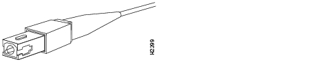
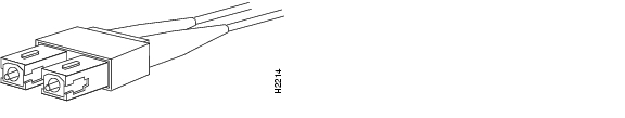
Use single-mode (for short-, intermediate- or long-reach configurations) optical fiber cable to connect your router to a network or to connect two OC3 ATM line card-equipped routers back to back. For SONET/SDH single-mode optical fiber connections, use two simplex SC-type cables (see Figure 1-5), or one duplex SC-type cable (see Figure 1-6).
Figure 1-5
Simplex SC-Type Cable and Connector
Figure 1-6 Duplex SC-Type Cable and Connector
Note
Attach one pair of simplex fiber cables between the line card and the device to which the line card is connected. Observe the receive (RX) and transmit (TX) cable relationship shown in Figure 1-7.
Note
Warning
Warning
Note
Figure 1-7 Transmit (TX) and Receive (RX) Ports on the OC3 ATM Line Card
Encapsulation Method Support
The following encapsulation methods are supported by the OC3 ATM line card:
•
•
•
Slot Locations on the Cisco 7304 Router
The following section describes the slot locations in the Cisco 7304 router. This section includes the following subsection:
•
Cisco 7304 Router Slot Numbering
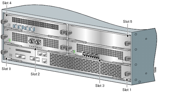
The OC3 ATM line card can be installed in slots 2 through 5 in Cisco 7304 routers. Figure 1-8 shows a Cisco 7304 with an OC3 ATM line card installed in slot 4.
Figure 1-8 Slots in the Cisco 7304 Router
Note
Identifying Interface Addresses
This section describes how to identify the interface address for the OC3 ATM line card in a Cisco 7304 router. Interface addresses specify the actual physical location of each interface on a router.
The interfaces on the OC3 ATM line card installed in a Cisco 7304 router maintain the same interface address regardless of whether other line cards are installed or removed. However, when you move a line card to a different slot, the first number in the interface address changes to reflect the new slot number.
Table 1-7 explains how to identify interface addresses.
Table 1-7 Identifying Interface Addresses
Cisco 7304 router
Slot-number/interface-port-number
Slot—0 through 5 1
2/0
1 Slot 0 and slot 1 are reserved for the network services engine (NSE).
Cisco 7304 Router Interface Addresses
This section describes how to identify the interface addresses used for the OC3 ATM line card in a Cisco 7304 router. The interface address is composed of a two-part number in the format slot-number/interface-port-number. See Table 1-7 for the interface address format.
In a Cisco 7304 router, slots are numbered, beginning with slot 0 (a dual-width slot reserved for the NSE-100) on the bottom, and continuing from the lower left to the upper right through slot 5.
Note
The interface address of the interface on an OC3 ATM line card in slot 2 is 2/0 (slot 2 and interface 0). If the OC3 ATM line card was in slot 4, this same interface would be numbered 4/0 (slot 4 and interface 0).
![]()
![]()
![]()
![]()
![]()
![]()
![]()
![]()
Posted: Tue Jun 28 09:59:43 PDT 2005
All contents are Copyright © 1992--2005 Cisco Systems, Inc. All rights reserved.
Important Notices and Privacy Statement.