|
|

Table Of Contents
Configuring the OC3 ATM Line Card
Using the EXEC Command Interpreter
Performing a Basic Configuration
Using show Commands to Verify the New Interface Status
Using the ping Command to Verify Network Connection
Performing an Advanced Configuration
Configuring the OC3 ATM Line Card for OC-3
Configuring Classical IP and ARP over ATM
Customizing the OC3 ATM Line Card
Configuring an ATM Interface for Local Loopback
Configuring an ATM Interface for External Loopback
Checking the Advanced Configuration
Testing and Troubleshooting the OC3 ATM Line Card
Commands That Display ATM Information
Example of PVCs with AAL5 and LLC/SNAP Encapsulation
Example of PVCs in a Fully Meshed Network
Example of SVCs in a Fully Meshed Network
Connecting Two OC3 ATM Line Cards Back to Back
Configuring the OC3 ATM Line Card
To continue your OC3 ATM line card installation, you must configure the OC-3 interface. This chapter contains the following sections:
•
Using the EXEC Command Interpreter
•
•
•
•
•
Using the EXEC Command Interpreter
You modify the configuration of your router through the software command interpreter called the EXEC (also called enable mode). You must enter the privileged level of the EXEC command interpreter with the enable command before you can use the configure command to configure a new interface or change the existing configuration of an interface. The system prompts you for a password if one has been set.
Tip
At the console terminal, use the following procedure to enter the privileged level:
Step 1
Router> enablePassword:Step 2
When you enter the correct password, the system displays the privileged-level system prompt (#):
Router#
Configuring the Interfaces
After you verify that the new OC3 ATM line card is installed correctly (the STATUS LED goes on), use the privileged-level configure command to configure the new interface. Have the following information available:
•
•
•
If you installed a new OC3 ATM line card or if you want to change the configuration of an existing interface, you must enter configuration mode to configure the new interface. If you replaced an OC3 ATM line card that was previously configured, the system recognizes the new interface and brings it up in its existing configuration.
For a summary of the configuration options available and instructions for configuring the interface on an OC3 ATM line card, refer to the appropriate configuration publications listed in "Related Documentation".
You execute configuration commands from the privileged level of the EXEC command interpreter, which usually requires password access. Contact your system administrator, if necessary, to obtain password access. (See Using the EXEC Command Interpreter for an explanation of the privileged level of the EXEC.)
This section contains the following subsections:
•
Shutting Down an Interface
Before you replace an interface cable, replace line cards, or remove an interface that you will not replace, use the shutdown command to shut down (disable) the interfaces. When you shut down an interface, it is designated administratively down in the show command displays.
Follow these steps to shut down an interface on the supported platform:
Step 1
Step 2
Router# configure terminalEnter configuration commands, one per line. End with CNTL/Z.Router(config)#Step 3
When you have finished, press Ctrl-Z—hold down the Control key while you press Z—or enter end or exit to exit configuration mode and return to the EXEC command interpreter.
Step 4
Router# copy running-config startup-config[OK]Router#The system displays an OK message when the configuration has been stored in NVRAM.
Step 5
Step 6
a.
b.
c.
show interfaces atm command followed by the interface address of the interface.For complete descriptions of software configuration commands, refer to the publications listed in "Related Documentation".
Performing a Basic Configuration
The following steps describe a basic interface configuration. Press the Return key after each step unless otherwise noted. At any time, you can exit the privileged level and return to the user level by entering disable at the prompt as follows:
Router# disableRouter>Follow these steps to perform a basic configuration:
Step 1
Router# configure terminalEnter configuration commands, one per line. End with CNTL/Z.Router(config)#Step 2
Step 3
Router(config-if)# ip address 10.0.0.0 255.255.255.0Step 4
Step 5
Step 6
Step 7
Router# copy running-config startup-config[OK]Router#The system displays an OK message when the configuration has been stored in NVRAM.
Tip
Checking the Configuration
After configuring the interface, use the show commands to display the status of the new interface and use the ping and loopback commands to check connectivity. This section includes the following subsections:
•
•
Using show Commands to Verify the New Interface Status
Table 4-4 demonstrates how you can use the show commands to verify that new interfaces are configured and operating correctly and that the OC3 ATM line card appears in them correctly. Sample displays of the output of selected show commands appear in the sections that follow. For complete command descriptions and examples, refer to the publications listed in "Related Documentation".
Note
This section includes the following subsections:
•
•
•
Choose the subsection appropriate for your system. Proceed to "Using the ping Command to Verify Network Connection" when you have finished using the show commands.
Using the show version or show hardware Commands
Display the configuration of the system hardware, the number of each interface type installed, the Cisco IOS software version, the names and sources of configuration files, and the boot images, by using the show version (or show hardware) command.
Note
Cisco 7304 Router
Following is an example of the show version command from a Cisco 7304 router with the OC3 ATM line card:
Router# show versionCisco Internetwork Operating System SoftwareIOS (tm) 7300 Software (C7300-IS-M), Version 12.1(20020129:220814) [ra-ws2 103]Copyright (c) 1986-2002 by cisco Systems, Inc.Compiled Mon 04-Feb-02 11:19 by raImage text-base: 0x40008970, data-base: 0x414E0000ROM: System Bootstrap, Version 12.1(20011026:021245) [hih-rommon_1_1 101], DEVELOPMENT SOFTWARECurrently running ROMMON from ROM 1BOOTLDR: 7300 Software (C7300-BOOT-M), Version 12.1(1.23.158), CISCO DEVELOPMENT TEST VERSIONc7300router uptime is 2 minutesSystem returned to ROM by power-onSystem image file is "tftp://223.255.254.254/muck/ra/c7300-is-mz"cisco 7300 (NSE100) processor (revision B) with 114688K/16384K bytes of memory.Processor board ID SCA053200L0R7000 CPU at 350Mhz, Implementation 39, Rev 3.2, 256KB L2, 1024KB L3 Cache4 slot midplane, Version 65.48Last reset from power-onBridging software.X.25 software, Version 3.0.0.PXF processor tmc0 running 'system:pxf/ucode1' v1.6 is activePXF processor tmc1 running 'system:pxf/ucode1' v1.6 is active1 FastEthernet/IEEE 802.3 interface(s)2 Gigabit Ethernet/IEEE 802.3 interface(s)4 ATM network interface(s)509K bytes of non-volatile configuration memory.16064K bytes of ATA compact flash in bootdisk (Sector size 512 bytes).31360K bytes of ATA compact flash in disk0 (Sector size 512 bytes).Configuration register is 0x100RouterUsing the show diag Command
Display the types of line cards installed in your system (and specific information about each) using the show diag slot command, where slot is the line card slot in a Cisco 7304.
Note
Cisco 7304 Router
Following is an example of the show diag slot command for an OC3 ATM line card in slot 2 of a Cisco 7304 router:
Router# show diag 2Slot 2:OC3 ATM Multimode Line Card, 2 portsLine Card state: ActiveInsertion time: 00:03:21 agoBandwidth points: 32EEPROM contents at hardware discovery:Hardware Revision : 2.0Unknown Field (type 0046): 00 00PCB Serial Number : CAB0549LNKQPart Number : 73-6828-02Board Revision : A0Fab Version : 02RMA Test History : 00RMA Number : 0-0-0-0RMA History : 00Deviation Number : 0-0Product Number : 7300-2OC3ATM-MMTop Assy. Part Number : 68-0000-00Manufacturing Test Data : 00 00 00 00 00 00 00 00Field Diagnostics Data : 00 00 00 00 00 00 00 00Calibration Data : Minimum: 0 dBmV, Maximum: 0 dBmVCalibration values :EEPROM format version 4 EEPROM contents (hex):0x00: 04 FF 40 03 74 41 02 00 46 00 00 C1 8B 43 41 420x10: 30 35 34 39 4C 4E 4B 51 82 49 1A AC 02 42 41 300x20: 02 02 03 00 81 00 00 00 00 04 00 80 00 00 00 000x30: CB 94 37 33 30 30 2D 32 4F 43 33 41 54 4D 2D 4D0x40: 4D 20 20 20 20 20 87 44 00 00 00 C4 08 00 00 000x50: 00 00 00 00 00 C5 08 00 00 00 00 00 00 00 00 C80x60: 09 00 00 00 00 00 00 00 00 00 C7 7C F6 44 3F 300x70: 00 00 00 00 00 00 00 00 00 00 00 00 07 08 64 320x80: 28 37 26 09 C4 64 32 28 32 DD 0C E4 64 32 28 430x90: 24 2E E0 AA 82 64 F4 24 00 00 00 00 00 00 00 000xA0: 00 00 00 00 00 00 F4 C8 FF FF FF FF FF FF FF FF0xB0: FF FF FF FF FF FF FF FF FF FF FF FF FF FF FF FF0xC0: FF FF FF FF FF FF FF FF FF FF FF FF FF FF FF FF0xD0: FF FF FF FF FF FF FF FF FF FF FF FF FF FF FF FF0xE0: FF FF FF FF FF FF FF FF FF FF FF FF FF FF FF FF0xF0: FF FF FF FF FF FF FF FF FF FF FF FF FF FF FF FFFPGA information:Current FPGA version : 0.3IOS bundled FPGA version : 0.10Using the show c7300 Command
Display the types of line cards installed in your system, their status, and insertion time by using the show c7300 command.
Note
Cisco 7304 Router
Following is an example of the show c7300 command for a Cisco 7304 router:
Router# show c7300Slot Card Type Status Insertion time---- --------- ------ --------------0,1 NSE100 Active 3d02h ago2,3 NSE100 Standby 3d02h ago4 2OC3-ATM Active 3d02h agoThe FPGA versions for the cards listed above are currentSystem is compliant with hardware configuration guidelines.Network IO Interrupt Throttling:throttle count=0, timer count=0active=0, configured=1netint usec=3999, netint mask usec=200Router#Using the show interfaces Command
The show interfaces command displays status information (including the physical slot and interface address) for the interfaces you specify. The example that follows specifies ATM interfaces.
For complete descriptions of interface subcommands and the configuration options available for Cisco 7304 interfaces, refer to the publications listed in the "Related Documentation"section.
Note
Cisco 7304 Router
Following is an example of the show interfaces atm command used with a Cisco 7304 router. In this example, the OC3 ATM line card is installed in slot 4 of a Cisco 7304 router:
Router# show interfaces atm 4/0ATM4/0 is up, line protocol is upHardware is OC-3 ATMInternet address is 40.1.1.40/24MTU 4470 bytes, sub MTU 4470, BW 149760 Kbit, DLY 80 usec,reliability 255/255, txload 1/255, rxload 1/255Encapsulation ATM, loopback not setKeepalive not supportedEncapsulation(s): AAL52048 maximum active VCs, 10 current VCCsVC idle disconnect time: 300 seconds0 carrier transitionsLast input 00:00:41, output 00:00:41, output hang neverLast clearing of "show interface" counters neverInput queue: 0/75/0/0 (size/max/drops/flushes); Total output drops: 0Queueing strategy: fifoOutput queue :0/40 (size/max)5 minute input rate 0 bits/sec, 0 packets/sec5 minute output rate 0 bits/sec, 0 packets/sec38 packets input, 4256 bytes, 0 no bufferReceived 0 broadcasts, 0 runts, 0 giants, 0 throttles0 input errors, 0 CRC, 0 frame, 0 overrun, 0 ignored, 0 abort38 packets output, 4104 bytes, 0 underruns0 output errors, 0 collisions, 0 interface resets0 output buffer failures, 0 output buffers swapped outUsing the ping Command to Verify Network Connection
Using the ping command, you can verify that an interface port is functioning properly. This section provides a brief description of this command. Refer to the publications listed in the "Related Documentation" section on page viii for detailed command descriptions and examples.
The ping command sends echo request packets out to a remote device at an IP address that you specify. After sending an echo request, the system waits a specified time for the remote device to reply. Each echo reply is displayed as an exclamation point (!) on the console terminal; each request that is not returned before the specified timeout is displayed as a period (.). A series of exclamation points (!!!!!) indicates a good connection; a series of periods (.....) or the messages [timed out] or [failed] indicate a bad connection.
Following is an example of a successful ping command to a remote server with the address 10.0.0.10:
Router# ping 10.0.0.10 <Return>Type escape sequence to abort.Sending 5, 100-byte ICMP Echoes to 10.0.0.10, timeout is 2 seconds:!!!!!Success rate is 100 percent (5/5), round-trip min/avg/max = 1/15/64 msRouter#If the connection fails, verify that you have the correct IP address for the destination and that the device is active (powered on), and repeat the ping command.
Using loopback Commands
The loopback test allows you to troubleshoot, detect, and isolate equipment malfunctions by testing the connection between the OC-3c interface and a remote device. The loop subcommand places an interface in internal loopback (also called local loopback) or line loopback mode, which enables test packets that are generated from the ping command to loop through a remote device or a cable. If the packets complete the loop, the connection is good. If not, you can isolate a fault to the remote device or the cable in the path of the loopback test.
Configuring an Interface for Internal Loopback
The default loopback setting is for no loopback. With internal (or local) loopback, packets from the router are looped back in the framer. Outgoing data gets looped back to the router interface without actually being transmitted. Internal loopback is useful for checking that the OC3 POS line card is working. To configure an interface for internal loopback, enter the loop internal command:
Router(config)# interface atm 3/0Router(config-if)# loop internalTo disable internal loopback, enter the no loop internal command.
Configuring an Interface for Line Loopback
The default loopback setting is for no loopback. With line loopback, the receive (RX) fiber is logically connected to the transmit (TX) optical fiber cable so that packets from the remote router are looped back to it. Incoming data gets looped around and retransmitted without actually being received. To configure an interface for line loopback, enter the loop line command:
Router(config)# interface atm 3/0Router(config-if)# loop lineTo disable line loopback, enter the no loop line command.
Performing an Advanced Configuration
The following sections include steps for configuring and customizing various ATM features of your OC3 ATM line card:
•
•
Configuring the OC3 ATM Line Card for OC-3
To configure the OC3 ATM line card for OC-3, perform the following tasks in interface configuration mode:
Step 1
Router# interface atm slot/portSpecify an ATM interface to configure. To use these commands, you need to be in interface configuration mode. (For the appropriate interface address to use for your system, see Table 4-3.)
Step 2
Router(config-if)# atm clock internalSelect the transmit clock source. This can be internal or derived from the receive clock through use of the no form of the command. By default, the receive clock source is used for the transmit clock.
Step 3
Router(config-if)# atm sonet stm-1Specify SONET framing: STM-1 (optional). Use the no form of this command to return to the default, STS-3c framing.
Configuring VCs
Virtual circuits (VCs) are point-to-point connections between remote hosts and routers. A VC is established for each ATM end node with which the router communicates. The characteristics of the VC are established when the VC is created and include the following:
•
•
•
When you assign a class of service to a VC for QoS management, the following default priority levels apply:
•
•
•
Each VC supports the following router functions:
•
•
•
•
By default, fast switching is enabled on all OC3 ATM line card interfaces. These switching features can be turned off with interface configuration commands. Optimum, flow, or CEF switching must be explicitly enabled for each interface.
Configuring PVCs
To use a permanent virtual circuit (PVC), you must configure the PVC in both the router and the ATM switch. PVCs remain active until the circuit is removed from either configuration.
When a PVC is configured, all of the configuration options are passed on to the OC3 ATM line card. You can write these PVCs into nonvolatile RAM (NVRAM); they are used when the system image is reloaded.
Some ATM switches might have point-to-multipoint PVCs that do the equivalent of broadcasting. If a point-to-multipoint PVC exists, it can be used as the sole broadcast PVC for all multicast requests.
To configure a PVC, perform the two required tasks in the following sections:
•
Creating a PVC
When you create any PVC, you create a virtual circuit descriptor (VCD) (a unique number) and attach it to the virtual path identifier (VPI) and virtual channel identifier (VCI). A VCD is an OC3 ATM line card-specific mechanism that identifies to the OC3 ATM line card the VPI-VCI pair to be used for a particular packet. The OC3 ATM line card requires this feature in order to manage the packets for transmission. The number chosen for the VCD is independent of the VPI-VCI pair used.
To create a PVC on the OC3 ATM line card interface, enter the following subcommand in interface configuration mode:
pvc [name] vpi/vci [ilmi | qsaal | l2transport]
The command values are as follows:
•
•
•
•
•
Optional Commands
ATM Adaption Layer and Encapsulation
•
–
Note
•
–
–
Other Optional Commands
•
•
•
The pvc command creates PVC n and attaches the PVC to VPI and VCI. When you create any PVC, you also specify the ATM adaptation layer (AAL) and encapsulation. The AAL used is specified by aal and encapsulation by encap.
The peak and average rate selection values are specified in kilobits per second. Omitting peak and average values causes the PVC and those values to default to the line rate, with the peak and average values being equal.
You can configure the PVC for communication with ILMI, which enables the router to receive Simple Network Management Protocol (SNMP) traps and new network prefixes. Refer to the Wide-Area Networking Configuration Guide for details.
You can also configure the PVC to send OAM F5 loopback cells, which verify connectivity on the virtual circuit. The remote end must respond by echoing back such cells.
The following example creates a PVC on interface 0 in a Cisco 7304 router with a line card in slot 4 with VPI 0 and VCI 6. The PVC uses AAL AAL5-MUX with IP.
Router# config terminalRouter(config)# interface ATM4/0.1 point-to-multipointRouter(config-subif)# ip address 10.1.1.1 255.255.255.252Router(config-subif)# pvc 0/6Router(config-if-atm-vc)# encapsulation aal5mux ipSee examples of PVC configurations in "ATM Configuration Examples".
Mapping a Protocol Address to a PVC
This section describes the procedure for mapping a protocol address to a PVC, which is a required task if you are configuring a PVC. The ATM interface supports a static mapping scheme that identifies the ATM addresses of remote hosts or routers. An address is specified as a virtual circuit descriptor (VCD) for a PVC (or network service access point [NSAP] address for SVC operation).
You enter mapping commands as groups. You first create a map list and then associate it with an interface. Begin the following steps in global configuration mode:
A map list can contain multiple map entries. The broadcast keyword specifies that this map entry is to be used when the corresponding protocol sends broadcast packets to the interface (for example, any network routing protocol updates). If you do not specify broadcast, the ATM software is prevented from sending routing protocol updates to the remote hosts.
If you do specify broadcast but do not set up point-to-multipoint signaling, pseudobroadcasting is enabled. To eliminate pseudobroadcasting and set up point-to-multipoint signaling on virtual circuits configured for broadcasting, refer to the Wide-Area Networking Configuration Guide.
You can create multiple map lists and associate them with one ATM interface only. You must create different map lists to associate with different interfaces. See the ATM Configuration Examples.
For further information on configuring ATM line cards for PVCs, refer to Wide-Area Networking Configuration Guide.
Configuring SVCs
ATM switched virtual circuit (SVC) service operates much like X.25 SVC service, although ATM allows much higher throughput. Virtual circuits are created and released dynamically, providing user bandwidth on demand. This service requires a signaling protocol between the router and the switch.
The ATM signaling software provides a method of dynamically establishing, maintaining, and clearing ATM connections at the User-Network Interface (UNI). The ATM signaling software conforms to the ATM Forum UNI 3.0 specification.
In UNI mode, the user is the router, and the network is an ATM switch. This is an important distinction. The Cisco router does not perform ATM-level call routing. Instead, the ATM switch does the ATM call routing, and the router routes packets through the resulting circuit. The router is viewed as the user and the LAN interconnection device at the end of the circuit, and the ATM switch is viewed as the network.
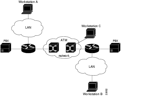
Figure 4-1 illustrates the router position in a basic ATM environment. The router is used primarily to interconnect LANs through an ATM network. Workstation C in Figure 4-1 is connected directly to the destination ATM switch. You can connect not only routers to ATM switches, but also any computer with an ATM interface that conforms to the ATM Forum UNI specification.
Figure 4-1 Basic ATM Environment
To use SVCs, complete the required tasks in the following sections:
•
•
For further information on configuring the OC3 ATM line card for SVCs, see the Wide-Area Networking Configuration Guide.
Configuring the PVC That Performs SVC Call Setup
Unlike X.25 service, which uses in-band signaling (connection establishment done on the same circuit as data transfer), ATM uses out-of-band signaling. One dedicated PVC exists between the router and the ATM switch, over which all SVC call establishment and call termination requests flow. After the call is established, data transfer occurs over the SVC, from router to router. The signaling that accomplishes the call setup and teardown is called Layer 3 signaling or the Q.2931 protocol.
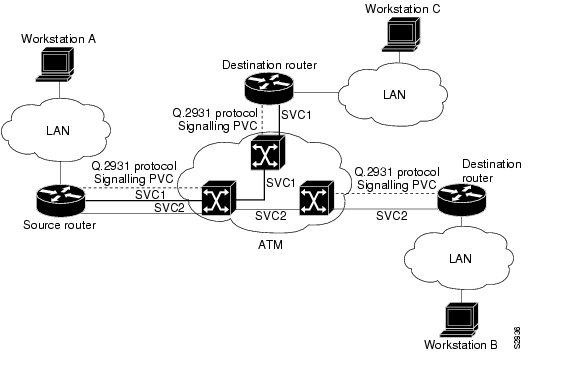
For out-of-band signaling, a signaling PVC must be configured before any SVCs can be set up. In Figure 4-2, a signaling PVC from the source router to the ATM switch is used to set up two SVCs. This is a fully meshed network; workstations A, B, and C can all communicate with one another.
Figure 4-2 One or More SVCs Require a Signaling PVC
To configure the signaling PVC for all SVC connections, enter the following command in interface configuration mode:
pvc [name] vpi/vci qsaal
Note
The VPI and VCI values must be configured consistently with the local switch. The standard value of VPI is 0; the standard value of VCI is 5.
See the "Example of SVCs in a Fully Meshed Network" section for a sample ATM signaling configuration.
Configuring the Network Service Access Point Address
Every ATM interface involved with signaling must be configured with a network service access point (NSAP) address. The NSAP address is the ATM address of the interface and must be unique across the network.
You can do one of the following to configure an NSAP address:
•
•
To configure the ESI and Selector fields, you must also configure a PVC to communicate with the switch through ILMI. The switch then provides the Prefix field of the NSAP address.
Configuring the Complete NSAP Address Manually
When you configure the ATM NSAP address manually, you must enter the entire address in hexadecimal format; that is, each digit entered represents a hexadecimal digit. To represent the complete NSAP address, you must enter 40 hexadecimal digits in the following format:
XX.XXXX.XX.XXXXXX.XXXX.XXXX.XXXX.XXXX.XXXX.XXXX.XX
Note
Because the interface has no default NSAP address, you must configure the NSAP address for SVCs. To set the ATM interface source NSAP address, enter the following command in interface configuration mode:
nsap-address nsap-address
The following is an example of an NSAP address assigned to ATM interface 4/0 on a Cisco 7304 router:
Router (config-if)# interface atm 4/0Router (config-if)# atm nsap-address AB.CDEF.01.234567.890A.BCDE.F012.3456.7890.1234.12You can display the ATM address for the interface by executing the show interfaces atm command.
Configuring the ESI and Selector Fields
You can configure the router to get the NSAP address prefix from the switch; however, the switch must be capable of delivering the NSAP address prefix to the router through ILMI, and the router must be configured with a PVC for communication with the switch through ILMI.
To configure the router to get the NSAP prefix from the switch and use locally entered values for the remaining fields of the address, complete the following tasks in interface configuration mode:
Step 1
Router# interface atm slot/portSpecify an ATM interface to configure. To use these commands, you need to be in interface configuration mode.
Step 2
Router(config-if)# pvc vcd 0 16 ilmiConfigure an ILMI PVC on an ATM main interface for communicating with the switch by using ILMI. (For the appropriate interface address to use for your system, see Table 4-3.)
Step 3
Router(config-if)# atm esi-address
esi.selector
Enter the ESI and selector fields of the NSAP address.
In the atm esi-address command, the esi argument is 6 hexadecimal bytes long (12 digits), and the selector argument is 1 hexadecimal byte long (2 digits).
In the following example on a Cisco 7304 router, the ESI and Selector field values are assigned, and the ILMI PVC is set up:
Router(config-if)# interface atm 4/0Router(config-if)# pvc 2 0 16 ilmiRouter(config-if)# atm esi-address 345678901234.12Configuring Classical IP and ARP over ATM
Cisco implements both the ATM Address Resolution Protocol (ARP) server and ATM ARP client functions described in RFC 1577. RFC 1577 models an ATM network as a logical IP subnetwork on a LAN.
The tasks required to configure classical IP and ARP over ATM depend on whether there are SVCs or PVCs in the environment. For further information, refer to the Wide-Area Networking Configuration Guide.
Customizing the OC3 ATM Line Card
You can customize the OC3 ATM line card. The features you can customize have default values that will probably suit your environment and not need to be changed. However, you might need to enter configuration commands, depending on the requirements for your system configuration and the protocols you plan to route on the interface. Perform the tasks in the following sections if you need to customize the OC3 ATM line card:
•
•
Note
Setting the MTU Size
Each ATM interface has a default maximum packet size or maximum transmission unit (MTU) size. On the OC3 ATM line card, this number defaults to 4470 bytes, the range being 64 through 9216 bytes. To set the maximum MTU size, enter the following command in interface configuration mode:
Router(config-if)# mtu bytesConfiguring an ATM Interface for Local Loopback
To configure an ATM interface for local loopback (useful for checking that the OC3 ATM line card is working by looping the transmit data back to the receive data), use the following command:
Router(config-if)# loopback diagnosticRouter(config-if)# no loopback diagnosticThe no form of the command turns off local loopback.
Configuring an ATM Interface for External Loopback
To configure an ATM interface for external loopback (useful for checking that the OC3 ATM line card is working by looping the receive data back to the transmit data), use the following command:
Router(config-if)# loopback lineRouter(config-if)# no loopback lineTo configure an ATM interface for external loopback at the cell level, use the following command:
Router(config-if)# loopback cellRouter(config-if)# no loopback cellTo configure an ATM interface for external loopback at the payload level, use the following command:
Router(config-if)# loopback payloadRouter(config-if)# no loopback payloadThe no form of each command turns off external loopback.
Checking the Advanced Configuration
After configuring the new interface, you can display its status. You can also display the current state of the ATM network and connected virtual circuits. To show current virtual circuits and traffic information, enter the following commands in EXEC mode. (For information about EXEC mode, see the "Using the EXEC Command Interpreter" section.)
Step 1
Router# show atm interface atm
slot-number/0
Display ATM-specific information about an ATM interface.
Step 2
Router# show atm mapDisplay the configured list of ATM static maps to remote hosts on an ATM network.
Step 3
Router# show atm trafficDisplay information about global traffic to and from all ATM networks connected to the router. Display a list of counters of all ATM traffic on this router.
Step 4
Router# show atm vc [vcd]Display ATM virtual circuit information about all PVCs and SVCs (or a specific virtual circuit).
Step 5
Router# show sscop1Display details for the ATM interface.
Step 6
Router# show atm arp-serverDisplay ATM ARP server table.
Step 7
Router# show atm ilmi-statusDisplay ATM ILMI information.
1 SSCOP = Service-Specific Connection-Oriented Protocol.
Traffic Management
The OC3 ATM line card supports the traffic-shaping parameters defined in Table 4-5. This ensures that generated traffic conforms to the ATM Forum Traffic Management Specification Version 4.0.
Note
Testing and Troubleshooting the OC3 ATM Line Card
The following sections provide suggested guidelines for troubleshooting the OC3 ATM line card. Use the ping command to verify network connectivity, the debug commands to help solve network problems, and the show commands to display the current state of the network.
OC3 ATM Line Card Statistics
The OC3 ATM line card maintains a count of certain errors and tracks the ATM controller facility performance. In addition to keeping a count of these errors, the OC3 ATM line card also takes snapshots of the last VCI/VPI that caused the error. Each OC3 ATM line card error counter is made up of 16 bits. Errors counted include the following:
•
•
•
•
•
•
The OC3 ATM line card provides line card-specific error statistics through the show interfaces atm command.
Note
The show controllers atm command displays the ATM framing information and ATM facility performance statistics.
The following is an example of the show controllers atm command from a Cisco 7304 router:
Router# show controllers atm 4/0Interface ATM4/0 is upHardware is OC-3 ATM, bandwidth OC3 (155000Kbps)Framer is PMC PM5351 S/UNI-TETRA (155-TETRA). SAR device is MXT4400 TSPPortMakerI AAL5 SAR firmware version for MXT4400 Reassembly SAR:major 0x1, minor 0x5, patch 0x0E, code level 0x0CPortMakerI AAL5 SAR firmware version for MXT4400 Segmemtation SAR:major 0x1, minor 0x5, patch 0x0E, code level 0x0Chwidb = 0x43553890, ds = 0x435F0CE0, ds_vp = 0x435553E0, ds_vc = 0x4369E200slot 4, slotunit 0, fci_type 0x0374, ticks 1000atm_db_flags = 0x00048308Current VCC count: current=10, peak=10Framer Information:Framing mode: SONET OC3 STS-3C. Clock source: line. Loopback mode: none.RXCP received cells: 2064, TXCP transmitted cells: 353253850Facility alarm:Phy stats:sbip lbip lfebe pbip pfebe hcse--------------------------------------------------------------9 12 l9 1 1 0sbip: Section BIP8lbip: Line BIP8/24lfebe: Line FEBEpbip: Path BIP8pfebe: Path FEBEhcse: Rx Cell HCS ErrorReassembler Counters:RXBytes: 75924RXCellsUnopenedChannel: 0RXPacketsCRC32Error: 0RXPacketsLECIDMatch: 0RXCellsCRC10Error: 0RXPacketsNoBuffers: 0RXPacketsTrailerLen: 0RXPacketsAbort: 0RXPacketsMPSError: 0RXPacketsDeEncapError: 0Segmenter Counters:TXBytes: 75924TXPacketsMPSError: 0Line Card FPGA Counters:RXPackets: 688 RXBytes: 75924TXPackets: 688 TXBytes: 75924Using the Debug ATM Commands
The following debug commands help to solve ATM network problems.
•
Router# debug atm packet•
Router# debug atm errors•
Router# debug atm events•
Router# debug atm oamAfter using a debug command, turn off debugging with the no debug command.
Commands That Display ATM Information
You can use ATM show commands to display the current state of the ATM network and the connected VCs.
•
Router# show atm vc [vcd]•
Router# show atm interfaces•
Router# show atm traffic•
Router# show atm mapshow atm vc
Use the show atm vc command to display the following types of statistics for all PVCs.
Router# show atm vcVCD / Peak Avg/Min BurstInterface Name VPI VCI Type Encaps SC Kbps Kbps Cells Sts4/0.1 1 1 10000 PVC SNAP UBR 149760 UP4/0.2 2 1 10001 PVC SNAP UBR 149760 UP4/0.3 3 1 10002 PVC SNAP UBR 149760 UP4/0.4 4 1 10003 PVC SNAP UBR 149760 UP4/0.5 5 1 10004 PVC SNAP UBR 149760 UPshow atm vc 2
Use the show atm vc n command, where n is the VCD unique index value, to display statistics for a given PVC.
Router# show atm vc 2ATM4/0.2: VCD: 2, VPI: 1, VCI: 10001UBR, PeakRate: 149760AAL5-LLC/SNAP, etype:0x0, Flags: 0xC20, VCmode: 0x0OAM frequency: 0 second(s)InARP frequency: 15 minutes(s)Transmit priority 4InPkts: 15332898, OutPkts: 15332754, InBytes: 3519887760, OutBytes: 3519877324InPRoc: 0, OutPRoc: 1InFast: 46, OutFast: 233, InAS: 0, OutAS: 0InPktDrops: 0, OutPktDrops: 0/0/0 (holdq/outputq/total)InByteDrops: 0, OutByteDrops: 0CrcErrors: 0, SarTimeOuts: 0, OverSizedSDUs: 0, LengthViolation: 0, CPIErrors: 0Out CLP=1 Pkts: 0OAM cells received: 0OAM cells sent: 0Status: UPVC 2 doesn't exist on interface ATM4/1Router#show interfaces atm
Use the show interfaces atm command to display statistics for the ATM interface you specify.
Note
Use the show atm interface atm command to display statistics for the ATM interface you specify by its interface address.
Router#show atm interface atm 4/1.1Interface ATM4/1:AAL enabled: AAL5 , Maximum VCs: 2047, Current VCCs: 0Maximum Transmit Channels: 0Max. Datagram Size: 4528PLIM Type: SONET - 155000Kbps, TX clocking: LINECell-payload scrambling: ONsts-stream scrambling: ON0 input, 0 output, 0 IN fast, 0 OUT fast, 0 out dropAvail bw = 155000Config. is ACTIVErouter#show atm interface atm
Use the show atm interface atm command to display statistics for the ATM interface you specify by its interface address.
Router# show atm interface atm 0/0ATM interface ATM 0/0:AAL enabled: AAL5, Maximum VCs: 2048, Current VCCs: 12Max. Datagram Size:4528, MIDs/VC: 1024PLIM Type:DS3 - 45Mbps, Framing is C-bit ADM,DS3 lbo: short, TX clocking: LINEScrambling: OFF227585 input, 227585 output, 0 IN fast, 0 OUT fastConfig. is ACTIVEUse the show sscop command to display SSCOP details for the ATM interface.
Use the show version command to display the configuration of the system hardware (the number of each interface processor type installed), the software version, the names and sources of configuration files, and the boot images.
Note
Use the show protocols command to display the global (system-wide) and interface-specific status of any configured Layer 3 protocol.
Use the show running-config command to display the currently running OC3 ATM line card configuration in RAM:
Router# show running-configinterface ATM4/0no ip address!interface ATM4/0.1 point-to-pointip address 10.1.1.1 255.255.255.252pvc 1/10000encapsulation aal5snap!ATM Configuration Examples
The following sections contain examples of ATM interface configurations. For detailed configuration examples, refer to the router software publications listed in Related Documentation.
•
•
•
•
For examples of emulated LAN configurations, refer to the Wide-Area Networking Configuration Guide.
Example of PVCs with AAL5 and LLC/SNAP Encapsulation
In the following example, PVC 5 is created on ATM interface 3/0 using LLC/SNAP encapsulation over AAL5. ATM interface 3/0 (IP address 10.0.0.1 255.0.0.0) connects with the ATM interface (IP address 10.0.0.2 255.0.0.0) at the other end of the connection. The static map list named atm1 declares that the next node is a broadcast point for multicast packets from IP.
interface ATM 3/0ip address 10.0.0.1 255.0.0.0map-group atm1atm pvc 5 0 1 aal5snap!no ip classless!map-list atm1ip 10.0.0.2 atm-vc 1 broadcastThe following example shows a typical ATM configuration for a PVC:
interface ATM 4/0ip address 10.0.0.1 255.0.0.0map-group atmatm pvc 1 1 1 aal5snapatm pvc 2 2 2 aal5snapatm pvc 6 6 6 aal5snapatm pvc 7 7 7 aal5snapclns router iso-igrp comet!Router iso-igrp cometnet 47.0004.0001.0000.0c00.6666.00!Router igrp 109network 10.255.255.255!ip domain-name CISCO.COM!map-list atmip 10.0.0.2 atm-vc 7 broadcastclns 47.0004.0001.0000.0c00.6e26.00 atm-vc 6 broadcastExample of PVCs in a Fully Meshed Network
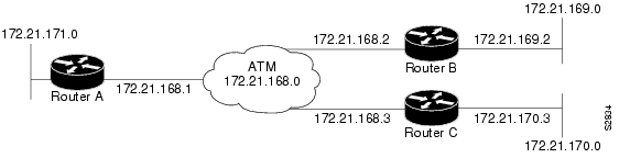
Figure 4-3 shows a fully meshed network. The configurations for Routers A, B, and C follow. In this example, the routers are configured to use PVCs. Fully meshed indicates that each network node has either a physical circuit or a virtual circuit connecting it to every other network node. The two map-list statements configured in Router A identify the ATM addresses of Routers B and C. The two map-list statements in Router B identify the ATM addresses of Routers A and C. The two map-list statements in Router C identify the ATM addresses of Routers A and B.
Figure 4-3 Fully Meshed ATM Configuration Example
Router A
ip routinginterface atm 4/0.1 multipointip address 10.21.168.1 255.255.255.0pvc 0/10encapsulation aal2snapprotocol ip 10.21.168.1 broadcastpvc 0/30encapsulation aal5snapprotocol ip 10.21.168.3 broadcastRouter B
ip routing!interface atm 2/0.1 multipointip address 10.21.168.2 255.255.255.0pvc 0/10encapsulation aal2snapprotocol ip 10.21.168.1 broadcastpvc 0/30encapsulation aal5snapprotocol ip 10.21.168.3 broadcastRouter C
ip routinginterface atm 4/0.1 multipointip address 10.21.168.3 255.255.255.0pvc 0/20encapsulation aal5snapprotocol ip 10.21.168.1 broadcastpvc 0/30encapsulation aal5snapprotocol ip 10.21.168.2 broadcastExample of SVCs in a Fully Meshed Network
The following example is also a configuration for the fully meshed network shown in Figure 4-3, but one in which SVCs are used. PVC 1 is the signaling PVC.
Router A
interface atm 4/0ip address 10.16.168.1 255.255.255.0atm nsap-address AB.CDEF.01.234567.890A.BCDE.F012.3456.7890.1234.12atm maxvc 1024pvc 0/5 qsaalexit!svc svc-1 nsap BC.CDEF.01.234567.890A.BCDE.F012.3456.7890.1334.13protocol ip 10.16.168.2exit!svc svc-2 nsap CA.CDEF.01.234567.890A.BCDE.F012.3456.7890.1334.12protocol ip 10.16.168.3exitRouter B
interface atm 2/0ip address 10.16.168.2 255.255.255.0atm nsap-address BC.CDEF.01.234567.890A.BCDE.F012.3456.7890.1334.13atm maxvc 1024pvc 0/5 qsaalexit!svc svc-1 nsap AB.CDEF.01.234567.890A.BCDE.F012.3456.7890.1234.12protocol ip 10.16.168.1exit!svc svc-2 nsap CA.CDEF.01.234567.890A.BCDE.F012.3456.7890.1334.12protocol ip 10.16.168.3exitRouter C
interface atm 4/0ip address 10.16.168.3 255.255.255.0atm nsap-address CA.CDEF.01.234567.890A.BCDE.F012.3456.7890.1334.12atm maxvc 1024pvc 0/5 qsaalexit!svc nsap AB.CDEF.01.234567.890A.BCDE.F012.3456.7890.1234.12protocol ip 10.16.168.1exit!svc nsap BC.CDEF.01.234567.890A.BCDE.F012.3456.7890.1334.13protocol ip 10.16.168.2exitConnecting Two OC3 ATM Line Cards Back to Back
Two routers, each containing an OC3 ATM line card, can be connected directly with a standard cable, which allows you to verify the operation of the ATM port or to directly link the routers to build a larger node.
To connect two routers, attach the cable between the ATM port on one and the ATM port on the other.
By default, the OC3 ATM line card "expects" a connected ATM switch to provide transmit clocking. To specify that the OC3 ATM line card generates the transmit clock internally for SONET physical layer interface module (PLIM) operation, add the atm clock internal command to your configuration.
Note
The following is an example of configuration file commands for two routers connected through their OC-3c interface:
First Router
interface atm 3/0atm clock internalinterface atm3/0.1 point-to-pointip address 10.0.0.1 255.0.0.0pvc 1/5encapsulation aal5snapprotocol ip 10.0.0.2 broadcastSecond Router
interface atm 3/0interface atm3/0.1 point-to-pointip address 10.0.0.2 255.0.0.0pvc 1/5encapsulation aal5snapUpgrading Your Bootdisk Image
The boot image contains a subset of the Cisco IOS software. This image is used to perform network booting or to load Cisco IOS images onto the router. This image is also used if the system cannot find a valid system image.
When you upgrade your Cisco IOS software to the minimum required software release (see Table 2-1 on page 2-2), we recommend that you also upgrade your bootdisk image. To upgrade your boot image, you can copy the new boot image from a network server to boot memory on your router. To copy a boot image from a Trivial File Transfer Protocol (TFTP) server to boot memory, complete the tasks shown in the following table:
For further information, such as how to set up the TFTP server, refer to the Configuration Fundamentals Configuration Guide.
CLI-Controlled OIR
Line cards can be removed from the Cisco 7304 router without disrupting data flow by using the hw-module slot slot # stop/start command in EXEC mode. The hw-module slot slot # stop command will stop traffic, shut down all line card interfaces, and deactivate the line card. The hw-module slot slot # start command resets the line card, puts the line card back online, and turns off the OIR LED.
Note
To remove and install an active line card in slot 2, proceed as follows:
Router# hw-module slot 2 stop
When the OIR LED turns green, the line card in slot 2 has been deactivated and can be physically removed and replaced with a new line card (see Line Card Removal and Installation.)
When the new line card is inserted in slot 2 it is automatically reset, put online, and the OIR LED is turned off.
![]()
![]()
![]()
![]()
![]()
![]()
![]()
![]()
Posted: Tue Jun 28 09:56:55 PDT 2005
All contents are Copyright © 1992--2005 Cisco Systems, Inc. All rights reserved.
Important Notices and Privacy Statement.