|
|

Table Of Contents
Overview of the Fast Ethernet SPA and Gigabit Ethernet SPA
4-Port 10/100 Fast Ethernet SPA and 2-Port 10/100/1000 Gigabit Ethernet SPA Features
Path of a Packet in the Ingress Direction
Path of a Packet in the Egress Direction
Displaying the SPA Hardware Type
Example of the show interfaces Command
Example of the show controllers Command
Overview of the Fast Ethernet SPA and Gigabit Ethernet SPA
This chapter provides an overview of the release history, and feature and Management Information Base (MIB) support for the Cisco 7304 MSC-100 with the 4-Port 10/100 Fast Ethernet SPA, and the 2-Port 10/100/1000 Gigabit Ethernet SPA.
This chapter includes the following sections:
•
Displaying the SPA Hardware Type
Release History
Table 5-1 provides the release and modification history for Ethernet SPA-related features and enhancements on the Cisco 7304 router.
Table 5-1 Release History
for Ethernet SPAs
Supported Features
This section provides a list of some of the primary features supported with the MSC and SPA hardware and software.
4-Port 10/100 Fast Ethernet SPA and 2-Port 10/100/1000 Gigabit Ethernet SPA Features
The following is a list of some of the significant hardware and software features supported by both the 4-Port 10/100 Fast Ethernet SPA and the 2-Port 10/100/1000 Gigabit Ethernet SPA:
•
•
•
•
•
•
•
–
–
•
–
–
•
•
•
•
For more information about FPGA support, see Chapter 16, "Upgrading Field-Programmable Devices."
Restrictions
As of Cisco IOS Release 12.2(20)S2, the 4-Port 10/100 Fast Ethernet SPA and the 2-Port 10/100/1000 Gigabit Ethernet SPA do not support the following features:
•
•
•
•
Supported MIBs
The following MIBs are supported in Cisco IOS Release 12.2(20)S2 for the 4-Port 10/100 Fast Ethernet SPA and 2-Port 10/100/1000 Gigabit Ethernet SPA on the Cisco 7304 router:
•
•
•
•
•
•
•
•
•
•
•
•
•
•
For more information about MIB support on the Cisco 7304 router, refer to the Cisco 7304 Router MIB Specifications Guide found at the following URL:
http://www.cisco.com/univercd/cc/td/doc/product/core/cis7300/7304mibs/
To locate and download MIBs for selected platforms, Cisco IOS releases, and feature sets, use Cisco MIB Locator found at the following URL:
http://tools.cisco.com/ITDIT/MIBS/servlet/index
If Cisco MIB Locator does not support the MIB information that you need, you can also obtain a list of supported MIBs and download MIBs from the Cisco MIBs page at the following URL:
http://www.cisco.com/public/sw-center/netmgmt/cmtk/mibs.shtml
To access Cisco MIB Locator, you must have an account on Cisco.com. If you have forgotten or lost your account information, send a blank e-mail to cco-locksmith@cisco.com. An automatic check will verify that your e-mail address is registered with Cisco.com. If the check is successful, account details with a new random password will be e-mailed to you. Qualified users can establish an account on Cisco.com by following the directions found at this URL:
SPA Architecture
This section provides an overview of the architecture of the 4-Port 10/100 Fast Ethernet SPA and describes the path of a packet in the ingress and egress directions. Some of these areas of the architecture are referenced in the SPA software and can be helpful to understand when troubleshooting or interpreting some of the SPA CLI and show command output.
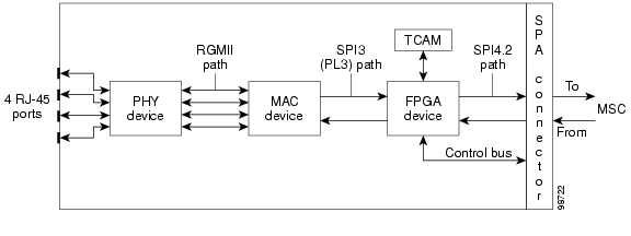
Figure 5-1 identifies some of the hardware devices that are part of the 4-Port 10/100 Fast Ethernet SPA and 2-Port 10/100/1000 Gigabit Ethernet SPA architecture. The figure shows the four RJ-45 ports that are supported by the Fast Ethernet SPA only.
Figure 5-1 4-Port 10/100 Fast Ethernet SPA Architecture
Every incoming and outgoing packet on the 4-Port 10/100 Fast Ethernet SPA goes through the physical (PHY), Media Access Control (MAC), and field-programmable gate array (FPGA) devices.
Path of a Packet in the Ingress Direction
The following steps describe the path of an ingress packet through the 4-Port 10/100 Fast Ethernet SPA:
1.
2.
3.
4.
5.
6.
If the interface is not operating in promiscuous mode, then the FPGA device performs two Ternary Content Addressable Memory (TCAM) table lookups to filter the received frame based on the MAC destination address and virtual LAN (VLAN) identifier. The allowable MAC destination addresses and VLAN IDs are based on the supported router configuration.
For more information about TCAM processing, see the "TCAM Filtering" section.
7.
8.
Path of a Packet in the Egress Direction
The following steps describe the path of an egress packet from the Cisco 7304 MSC-100 through the 4-Port 10/100 Fast Ethernet SPA:
1.
2.
3.
4.
5.
6.
TCAM Filtering
The 4-Port 10/100 Fast Ethernet SPA and 2-Port 10/100/1000 Gigabit Ethernet SPA support two TCAM regions per interface. One region is for MAC destination address filtering (2048 total entries, with 512 entries per interface on the Fast Ethernet SPA and 1024 entries per interface on the Gigabit Ethernet SPA), and the other is for VLAN ID filtering (4096 total entries, with 1024 entries per interface on the Fast Ethernet SPA and 2048 entries per interface on the Gigabit Ethernet SPA). Filtering is enabled by default when the interface is not operating in promiscuous mode. If the interface is operating in promiscuous mode, or if the TCAM table is full, then no filtering occurs. Otherwise, enabling and disabling of filtering is not user-configurable.
The TCAM entries support permit filtering only. For example, if a MAC destination address is not in the TCAM table for the interface, the frame is dropped. The MAC destination address entries are added to the TCAM for such things as multicast addresses of routing protocols. Unicast addresses do not typically appear in the table. By default when the router reloads, three destination addresses are added to the TCAM table: the local interface address, the Ethernet broadcast address, and the Ethernet multicast address.
For VLAN filtering, two default VLAN ID 0 entries always appear in the table and represent the local interface port for handling of promiscuous mode and non-VLAN packets. Additional VLAN IDs appear in the table based on your interface configuration.
To display the status of the TCAM tables on an interface, use the show controllers fastethernet command or show controllers gigabitethernet command.
Displaying the SPA Hardware Type
To verify the SPA hardware type that is installed in your Cisco 7304 router, you can use the show interfaces command or the show controllers command. There are several other commands on the Cisco 7304 router that also provide SPA hardware information, including the show c7300 and the show diag commands. For more information about these commands, see Chapter 18, "Command Reference."
Table 5-2 shows the hardware description that appears in the show command output for each type of SPA that is supported on the Cisco 7304 router.
Example of the show interfaces Command
The following example shows output from the show interfaces fastethernet command on a Cisco 7304 router with a 4-Port 10/100 Fast Ethernet SPA installed in slot 4:
Router# show interfaces fastethernet 4/0/0FastEthernet4/0/0 is up, line protocol is upHardware is SPA-4FE-7304, address is 00b0.64ff.5d80 (bia 00b0.64ff.5d80)Internet address is 192.168.50.1/24...Example of the show controllers Command
The following example shows output from the show controllers fastethernet command on a Cisco 7304 router with a 4-Port 10/100 Fast Ethernet SPA installed in slot 4:
Router# show controllers fastethernet 4/0/0Interface FastEthernet4/0/0Hardware is SPA-4FE-7304Connection mode is auto-negotiationInterface state is up, link is upConfiguration is Auto Speed, Auto DuplexSelected media-type is RJ45...
![]()
![]()
![]()
![]()
![]()
![]()
![]()
![]()
Posted: Tue Mar 15 15:12:15 PST 2005
All contents are Copyright © 1992--2005 Cisco Systems, Inc. All rights reserved.
Important Notices and Privacy Statement.