|
|

Table Of Contents
Inserting an EPA into a Modular Gigabit Ethernet Line Card
Inserting an EPA into a Modular Gigabit Ethernet Line Card
December 16, 2005
Document Part Number: 78-17296-01 A0
To insert an EPA into the Modular Gigabit Ethernet line card, follow these steps:
Warning
You must use an ESD-preventive wrist or ankle strap to do this procedure. Attach an ESD-preventive wrist or ankle strap and follow its directions for use, before you do this procedure.
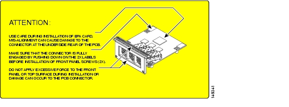
Step 1
Figure 1 Locations of Labels and Reference Points on the EPA
Caution
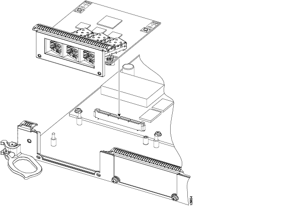
Step 2
Figure 2 Mating the Connector of the EPA to the Line Card
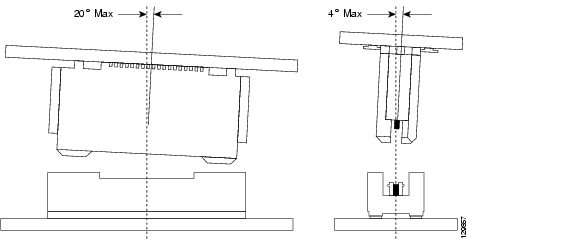
Figure 3 Side Views - Mating the Connector of the EPA to the Line Card
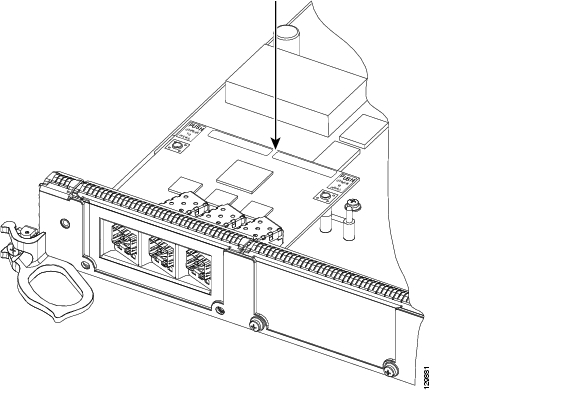
Step 3
Figure 4 Press on the Rear Outer Corners of the EPA
Figure 5 Rear Outer Corners of the EPA (Close-up)
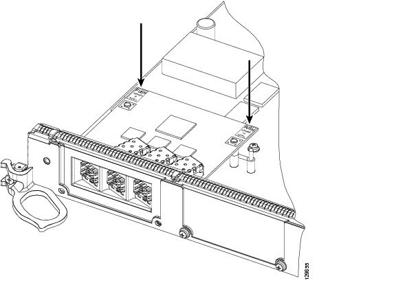
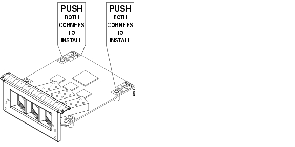
Step 4
Figure 6 Press on the White Labels on the EPA
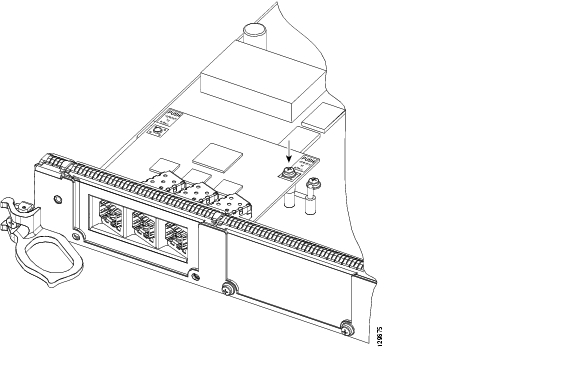
Step 5
Caution
Figure 7 Inserting and Tightening the Screw on the EPA
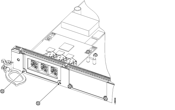
Step 6
Caution
Figure 8 Inserting the 2 screws on the Faceplate of the Line Card
CCSP, CCVP, the Cisco Square Bridge logo, Follow Me Browsing, and StackWise are trademarks of Cisco Systems, Inc.; Changing the Way We Work, Live, Play, and Learn, and iQuick Study are service marks of Cisco Systems, Inc.; and Access Registrar, Aironet, ASIST, BPX, Catalyst, CCDA, CCDP, CCIE, CCIP, CCNA, CCNP, Cisco, the Cisco Certified Internetwork Expert logo, Cisco IOS, Cisco Press, Cisco Systems, Cisco Systems Capital, the Cisco Systems logo, Cisco Unity, Empowering the Internet Generation, Enterprise/Solver, EtherChannel, EtherFast, EtherSwitch, Fast Step, FormShare, GigaDrive, GigaStack, HomeLink, Internet Quotient, IOS, IP/TV, iQ Expertise, the iQ logo, iQ Net Readiness Scorecard, LightStream, Linksys, MeetingPlace, MGX, the Networkers logo, Networking Academy, Network Registrar, Packet, PIX, Post-Routing, Pre-Routing, ProConnect, RateMUX, ScriptShare, SlideCast, SMARTnet, StrataView Plus, TeleRouter, The Fastest Way to Increase Your Internet Quotient, and TransPath are registered trademarks of Cisco Systems, Inc. and/or its affiliates in the United States and certain other countries.
All other trademarks mentioned in this document or Website are the property of their respective owners. The use of the word partner does not imply a partnership relationship between Cisco and any other company. (0502R)
© 2005 Cisco Systems, Inc. All rights reserved.
![]()
![]()
![]()
![]()
![]()
![]()
![]()
![]()
Posted: Fri Dec 16 16:17:14 PST 2005
All contents are Copyright © 1992--2005 Cisco Systems, Inc. All rights reserved.
Important Notices and Privacy Statement.