|
|

Table Of Contents
Remote Access VPN Business Scenarios
Configuring a Cisco IOS VPN Gateway for Use with Cisco Secure VPN Client Software
Configuring a Cisco IOS VPN Gateway for Use with Microsoft Dial-Up Networking
Configuring Cisco IOS Firewall Authentication Proxy
Configuring Authentication, Authorization, and Accounting
Configuring the Authentication Proxy
Verifying the Authentication Proxy
Comprehensive Configuration Examples
Remote Access VPN Business Scenarios
This chapter explains the basic tasks for configuring an IP-based, remote access Virtual Private Network (VPN) on a Cisco IOS VPN gateway. In the remote access VPN business scenario, a remote user running VPN client software on a PC establishes a connection to the headquarters gateway.
Note
The configurations in this chapter utilize a Cisco 7100 series VPN gateway. If you have a Cisco IOS VPN gateway model other than the Cisco 7100 series VPN gateway, your configurations will differ slightly, most notably in the port slot numbering. Please refer to your model configuration guide for detailed configuration information. Please refer to the "Obtaining Documentation" section for instructions about locating product documentation.
Note
This chapter includes the following sections:
•
•
•
•
Note
Scenario Description
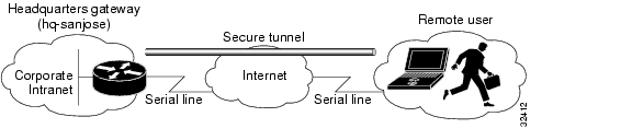
Figure 4-1 shows a headquarters network providing a remote user access to the corporate intranet. In this scenario, the headquarters and remote user are connected through a secure tunnel that is established over an IP infrastructure (the Internet). The remote user is able to access internal, private web pages and perform various IP-based network tasks.
Figure 4-1 Remote Access VPN Business Scenario
Figure 4-2 shows the physical elements of the scenario. The Internet provides the core interconnecting fabric between the headquarters and remote user. The headquarters is using a Cisco IOS VPN gateway (either a Cisco 7100 series with an Integrated Service Module (ISM) or VPN Accelerator Module (VAM), a Cisco 7200 series with an Integrated Service Adaptor (ISA) or VAM, or a Cisco 3600 series concentrator), and the remote user is running VPN client software on a PC.
The tunnel is configured on the first serial interface in chassis slot 1 (serial 1/0) of the headquarters and remote office routers. Fast Ethernet interface 0/0 of the headquarters router is connected to a corporate server and Fast Ethernet interface 0/1 is connected to a web server.
Figure 4-2 Remote Access VPN Scenario Physical Elements
The configuration steps in the following sections are for the headquarters router. Comprehensive configuration examples for the headquarters router are provided in the "Comprehensive Configuration Examples" section. Table 4-1 lists the physical elements of the scenario.
Configuring a Cisco IOS VPN Gateway for Use with Cisco Secure VPN Client Software
Using Cisco Secure VPN Client software, a remote user can access the corporate headquarters network through a secure IPSec tunnel. Although Cisco IOS VPN gateways support Cisco Secure VPN Client software, this guide does not explain how to configure your gateway for use with it. For detailed information on configuring client-initiated VPNs using Cisco Secure VPN Client software, refer to the Cisco Secure VPN Client Solutions Guide publication.
Configuring a Cisco IOS VPN Gateway for Use with Microsoft Dial-Up Networking
Using Microsoft Dial-Up Networking (DUN), available with Microsoft Windows 95, Microsoft Windows 98, Microsoft Windows NT 4.0, and Microsoft Windows 2000, a remote user can use Point-to-Point Tunneling Protocol (PPTP) with Microsoft Point-to-Point Encryption (MPPE) to access the corporate headquarters network through a secure tunnel.
Employing PPTP/MPPE, users can use any Internet service provider (ISP) account and any Internet-routable IP address to access the edge of the enterprise network. At the edge, the IP packet is detunneled and the IP address space of the enterprise is used for traversing the internal network. MPPE provides an encryption service that protects the datastream as it traverses the Internet. MPPE is available in two strengths: 40-bit encryption, which is widely available throughout the world, and 128-bit encryption, which may be subject to certain export controls when used outside the United States.
Note
Alternatively, a remote user with client software bundled into Microsoft Windows 2000 can use Layer 2 Tunneling Protocol (L2TP) with IPSec to access the corporate headquarters network through a secure tunnel.
Because L2TP is a standard protocol, enterprises can enjoy a wide range of service offerings available from multiple vendors. L2TP implementation is a solution that provides a flexible, scalable remote network access environment without compromising corporate security or endangering mission-critical applications.
Note
This section includes the following topics:
Configuring PPTP/MPPE
PPTP is a network protocol that enables the secure transfer of data from a remote client to a private enterprise server by creating a VPN across TCP/IP-based data networks. PPTP supports on-demand, multiprotocol, virtual private networking over public networks, such as the Internet.
MPPE is an encryption technology developed by Microsoft to encrypt point-to-point links. These PPP connections can be over a dialup line or over a VPN tunnel. MPPE works as a subfeature of Microsoft Point-to-Point Compression (MPPC).
MPPE uses the RC4 algorithm with either 40- or 128-bit keys. All keys are derived from the cleartext authentication password of the user. RC4 is stream cipher; therefore, the sizes of the encrypted and decrypted frames are the same size as the original frame. The Cisco implementation of MPPE is fully interoperable with that of Microsoft and uses all available options, including historyless mode. Historyless mode can increase throughput in high-loss environments such as VPNs.
Note
Note
This section contains basic steps to configure PPTP/MPPE and includes the following tasks:
•
Configuring a Virtual Template for Dial-In Sessions
Using virtual templates, you can populate virtual-access interfaces with predefined customized configurations. To configure your Cisco IOS VPN gateway to create virtual-access interfaces from a virtual template for incoming PPTP calls, use the following commands beginning in global configuration mode:
Step 1
hq-sanjose(config)# interface virtual-template
number
Creates the virtual template that is used to clone virtual-access interfaces.
Step 2
hq-sanjose(config-if)# ip unnumbered
interface-type number
Specifies the IP address of the interface the virtual-access interfaces uses.
Step 3
hq-sanjose(config-if)# ppp authentication ms-chapEnables MS-CHAP authentication using the local username database. All windows clients using MPPE need to use MS-CHAP.
Step 4
hq-sanjose(config-if)# ip local pool default
first-ip-address last-ip-address
Configures the default local pool of IP addresses that will be used by clients.
Step 5
hq-sanjose(config-if)# peer default ip address
pool {default|name}
Returns an IP address from the default pool to the client.
Step 6
hq-sanjose(config-if)# ip mroute-cacheDisables fast switching of IP multicast.
Step 7
hq-sanjose(config-if)# ppp encrypt mppe {auto | 40
| 128} [passive | required] [stateful]
(Optional) Enables MPPE encryption on the virtual template1 if you are not using an ISM with your Cisco 7100 series router. If you are using an ISM with a Cisco 7100 series router, see the "Configuring MPPE" section.
1 Stateful MPPE encryption changes the key every 255 packets. Stateless (historyless) MPPE encryption generates a new key for every packet. Stateless MPPE is only supported in recent versions of Dial-Up Networking (DUN1.3).
Configuring PPTP
To configure a Cisco IOS VPN gateway to accept tunneled PPP connections from a client, use the following commands beginning in global configuration mode:
Configuring MPPE
Note
To configure MPPE on your Cisco IOS VPN gateway, use the following commands beginning in global configuration mode:
Step 1
hq-sanjose(config)# controller isa slot/portEnter controller configuration mode on the ISM card.
Step 2
hq-sanjose(config-controller)# encryption mppeEnables MPPE encryption.
Verifying PPTP/MPPE
After you complete a connection, enter the show vpdn tunnel command or the show vpdn session command to verify your PPTP and MPPE configuration.The following example contains typical output:
hq-sanjose# show vpdn tunnel | show vpdn sessionPPTP Tunnel Information (Total tunnels=1 sessions=1)LocID RemID Remote Name State Remote Address Port Sessions22 22 172.16.230.29 estabd 172.16.230.29 1374 1Configuring L2TP/IPSec
L2TP is an extension of the Point-to-Point (PPP) Protocol and is often a fundamental building block for VPNs. L2TP merges the best features of two other tunneling protocols: Layer 2 Forwarding (L2F) from Cisco Systems and PPTP from Microsoft. L2TP is an Internet Engineering Task Force (IETF) emerging standard.
Note
This section contains basic steps to configure L2TP/IPSec and includes the following tasks:
•
•
Configuring a Virtual Template for Dial-In Sessions
To configure your Cisco IOS VPN gateway to create virtual-access interfaces from a virtual template for incoming L2TP calls, refer to the "Configuring a Virtual Template for Dial-In Sessions" section.
Note
Configuring L2TP
To configure a Cisco IOS VPN gateway to accept tunneled L2TP connections from a client, use the following commands beginning in global configuration mode:
Verifying L2TP
Enter the show vpdn tunnel command to verify your LT2P configuration.
hq-sanjose# show vpdn tunnelL2TP Tunnel and Session Information (Total tunnels=5 sessions=5)LocID RemID Remote Name State Remote Address Port Sessions10 8 7206b est 10.0.0.1 1701 1LocID RemID TunID Intf Username State Last Chg Fastswitch4 6 10 Vi1 las est 01:44:39 enabledConfiguring Encryption and IPSec
For detailed information on configuring encryption and IPSec, refer to the following sections of this guide:
•
•
•
•
•
•
Note
•
•
•
•
Note
Configuring Cisco IOS Firewall Authentication Proxy
Using the Cisco IOS firewall authentication proxy feature, network administrators can apply specific security policies on a per-user basis. Users can be identified and authorized on the basis of their per-user policy, and access privileges tailored on an individual basis are possible, in contrast with general policy applied across multiple users.
With the authentication proxy feature, users can log into the network or access the Internet via HTTP, and their specific access profiles are automatically retrieved and applied from an authentication server. The user profiles are active only when there is active traffic from the authenticated users.
The authentication proxy is compatible with Network Address Translation (NAT), Context-based Access Control (CBAC), IP Security (IPSec) encryption, and VPN client software.
This section contains basic steps to configure the Cisco IOS Firewall Authentication Proxy and includes the following tasks:
•
•
•
Configuring Authentication, Authorization, and Accounting
You must configure the authentication proxy for Authentication, Authorization, and Accounting (AAA) services. Use the following commands in global configuration mode to enable authorization and to define the authorization methods:
In addition to configuring AAA on the firewall router, the authentication proxy requires a per-user access profile configuration on the AAA server. To support the authentication proxy, configure the AAA authorization service "auth-proxy" on the AAA server as outlined here:
•
default authorization = permitkey = ciscouser = newuser1 {login = cleartext ciscoservice = auth-proxy{priv-lvl=15proxyacl#1="permit tcp any any eq 26"proxyacl#2="permit icmp any host 60.0.0.2"proxyacl#3="permit tcp any any eq ftp"proxyacl#4="permit tcp any any eq ftp-data"proxyacl#5="permit tcp any any eq smtp"proxyacl#6="permit tcp any any eq telnet"•
•
•
•
•
Configuring the HTTP Server
To use the authentication proxy, you must also enable the HTTP server on the firewall and set the HTTP server authentication method to use AAA. Enter the following commands in global configuration mode:
Configuring the Authentication Proxy
To configure the authentication proxy, use the following commands beginning in global configuration mode:
Verifying the Authentication Proxy
To check the current authentication proxy configuration, use the show ip auth-proxy configuration command in privileged EXEC mode. In the following example, the global authentication proxy idle timeout value is set to 60 minutes, the named authentication proxy rule is "pxy," and the idle timeout value for this named rule is 1 minute. The display shows that no host list is specified, meaning that all connections initiating HTTP traffic at the interface are subject to the authentication proxy rule:
router# show ip auth-proxy configurationAuthentication cache time is 60 minutesAuthentication Proxy Rule ConfigurationAuth-proxy name pxyhttp list not specified auth-cache-time 1 minutesTo verify that the authentication proxy is successfully configured on the router, ask a user to initiate an HTTP connection through the router. The user must have authentication and authorization configured at the AAA server. If the user authentication is successful, the firewall completes the HTTP connection for the user. If the authentication is unsuccessful, check the access list and the AAA server configurations.
Display the user authentication entries using the show ip auth-proxy cache command in privileged EXEC mode. The authentication proxy cache lists the host IP address, the source port number, the timeout value for the authentication proxy, and the state of the connection. If the authentication proxy state is HTTP_ESTAB, the user authentication was successful.
router# show ip auth-proxy cacheAuthentication Proxy CacheClient IP 192.168.25.215 Port 57882, timeout 1, state HTTP_ESTABWait for one minute, which is the timeout value for this named rule, and ask the user to try the connection again. After one minute, the user connection is denied because the authentication proxy has removed the user authentication entry and any associated dynamic ACLs. The user is presented with a new authentication login page and must log in again to gain access through the firewall.
Comprehensive Configuration Examples
This section contains PPTP/MPPE, and L2TP/IPSec comprehensive sample configurations for the headquarters gateway.
PPTP/MPPE Configuration
hq-sanjose# show running-configCurrent configuration!version 12.0service timestamps debug uptimeservice timestamps log uptimeno service password-encryption!hostname mp12!no logging console guaranteedenable password lab!username tester41 password 0 lab41!ip subnet-zerono ip domain-lookup!vpdn enable!vpdn-group 1! Default PPTP VPDN groupaccept-dialinprotocol pptpvirtual-template 1local name cisco_pns!memory check-interval 1!controller ISA 5/0encryption mppe!process-max-time 200!interface FastEthernet0/0ip address 10.1.3.3 255.255.255.0no ip directed-broadcastduplex autospeed auto!interface FastEthernet0/1ip address 10.1.6.4 255.255.255.0no ip directed-broadcastduplex autospeed auto!interface Serial1/0no ip addressno ip directed-broadcastshutdownframing c-bitcablelength 10dsu bandwidth 44210!interface Serial1/1no ip addressno ip directed-broadcastshutdownframing c-bitcablelength 10dsu bandwidth 44210!interface FastEthernet4/0no ip addressno ip directed-broadcastshutdownduplex half!interface Virtual-Template1ip unnumbered FastEthernet0/0no ip directed-broadcastip mroute-cacheno keepaliveppp encrypt mppe 40ppp authentication ms-chap!ip classlessip route 172.29.1.129 255.255.255.255 1.1.1.1ip route 172.29.63.9 255.255.255.255 1.1.1.1no ip http server!line con 0exec-timeout 0 0transport input noneline aux 0line vty 0 4login!aaa new-modelaaa authentication login default tacacs+ radius!Set up the aaa new model to use the authentication proxy.aaa authorization auth-proxy default tacacs+ radius!Define the AAA servers used by the routertacacs-server host 172.31.54.143tacacs-server key ciscoradius-server host 172.31.54.143radius-server key cisco!! Enable the HTTP server on the router:ip http server! Set the HTTP server authentication method to AAA:ip http authentication aaa!Define standard access list 61 to deny any host.access-list 61 deny any! Use ACL 61 to deny connections from any host to the HTTP server.ip http access-class 61!!set the global authentication proxy timeout value.ip auth-proxy auth-cache-time 60!Apply a name to the authentication proxy configuration rule.ip auth-proxy name HQ_users http!! Apply the authentication proxy rule at an interface.interface e0ip address 10.1.1.210 255.255.255.0ip auth-proxy HQ_users!endL2TP/IPSec Configuration
hq-sanjose# show running-configCurrent configuration:!version 12.0service timestamps debug uptimeservice timestamps log uptimeno service password-encryption!hostname LNS!enable password ww!username LNS password 0 tunnelpassusername test@cisco.com password 0 ciscoip subnet-zero!vpdn enable!vpdn-group 1accept dialin l2tp virtual-template 1 remote LAClocal name LNS!crypto isakmp policy 1authentication pre-sharegroup 2lifetime 3600crypto isakmp key cisco address 172.1.1.1!crypto ipsec transform-set testtrans esp-des!!crypto map l2tpmap 10 ipsec-isakmpset peer 172.1.1.1set transform-set testtransmatch address 101!interface Ethernet 0/0ip address 10.1.3.3 255.255.255.0no ip directed-broadcastno keepalive!interface Ethernet 0/1no ip addressno ip directed-broadcastshutdown!interface Virtual-Template1ip unnumbered Ethernet0no ip directed-broadcastno ip route-cachepeer default ip address pool mypoolppp authentication chap!interface Serial 1/0ip address 172.17.2.4 255.255.255.0no ip directed-broadcastno ip route-cacheno ip mroute-cacheno fair-queueclockrate 1300000crypto map l2tpmap!interface Serial 0/0no ip addressno ip directed-broadcastshutdown!ip local pool mypool 172.16.3.1 172.20.10.10no ip classless!access-list 101 permit udp host 172.17.2.4 eq 1701 host 172.1.1.1 eq 1701!line con 0exec-timeout 0 0transport input noneline aux 0line vty 0 4password ciscologin!aaa new-modelaaa authentication login default tacacs+ radius!Set up the aaa new model to use the authentication proxy.aaa authorization auth-proxy default tacacs+ radius!Define the AAA servers used by the routertcacs-server host 172.31.54.143tacacs-server key ciscoradius-server host 172.31.54.143radius-server key cisco!! Enable the HTTP server on the router:ip http server! Set the HTTP server authentication method to AAA:ip http authentication aaa!Define standard access list 61 to deny any host.access-list 61 deny any! Use ACL 61 to deny connections from any host to the HTTP server.ip http access-class 61!!set the global authentication proxy timeout value.ip auth-proxy auth-cache-time 60!Apply a name to the authentication proxy configuration rule.ip auth-proxy name HQ_users http!! Apply the authentication proxy rule at an interface.interface e0ip address 10.1.1.210 255.255.255.0ip auth-proxy HQ_users!end
![]()
![]()
![]()
![]()
![]()
![]()
![]()
![]()
Posted: Mon Dec 20 09:16:41 PST 2004
All contents are Copyright © 1992--2004 Cisco Systems, Inc. All rights reserved.
Important Notices and Privacy Statement.