|
|

You can install the single attachment SBus adapter in any SPARCstation or SPARCserver. The dual attachment adapter requires two adjacent SBus slots. This chapter describes how to install the SBus adapter in Sun workstations and servers:
This chapter also discusses how to identify SBus slots in each workstation, how to decide which SBus slot(s) to use, and how to properly install SBus adapters.
To install the SBus adapter, make sure that you complete the following procedures and have the required tools available:
The remainder of this chapter describes these procedures in detail.
Before you install the SBus adapter, halt and power down the SPARCstation.
 | Caution You should halt the SPARCstation in an orderly manner. Make sure you close all open files and terminate processes. Abruptly aborting a program may damage files. |
To halt the system, take the following steps:
Step 1 Save all your work. Quit any application that may lose information when the SPARCstation halts.
Step 2 Log in to the system as superuser and enter either of the following commands:
/etc/halt
or
/etc/fasthalt
Step 3 When the system halts, turn OFF the power to the hardware devices in the following order:
 | Caution Do not disconnect the power cord from the system power outlet or the wall socket. This connection provides the ground path necessary to safely install your SBus adapter. |
For additional information about halting your system, refer to the manual for your workstation.
SBus adapter faceplates have two different alignment schemes. One scheme is designed to fit under two hooks in the workstation back panel. Another design fits two tabs into slots in the top of the backpanel opening.
In the following procedures you will be told to remove the sheet-metal protector plate from the inner back panel of your workstation. If the removed protector plate does not have two alignment tabs on the top, you will need to remove the tab adapter bracket from the SBus adapter faceplate. Figure 4-1 shows the adapter faceplate tab bracket.

To remove the adapter bracket, remove the two attachment screws shown in Figure 4-1. Now your SBus adapter faceplate will fit under the two hooks in your workstation back panel.
Save the adapter faceplate tab adapter bracket and screws in case you need to use them when installing the SBus adapter in other systems.
This section explains how to install the SBus adapter in a SPARCstation or SPARCserver.
 | Warning Make sure your SPARCstation is powered down before you begin this procedure. (See the earlier section in this chapter, "Halt and Power Down the SPARCstation," for instructions on how to power down your workstation.) |
Step 1 Remove the cover from your system. Refer to the system installation guide provided with your SPARCstation or SPARCserver for specific instructions on removing the cover.
Step 2 Identify the SBus slots. The SBus adapter can be installed in any Master (M) SBus slot. Refer to the system installation guide provided with your SPARCstation or SPARCserver for details on M SBus slot locations and numbers.
Step 3 Remove the sheet-metal protector plate for the desired slot from the inner back panel of the system.
Step 4 If you are installing the SBus adapter in a SPARCstation 10 or 20, remove the top bracket from the adapter faceplate.
Step 5 Slide the SBus adapter at an angle into the back panel of the workstation. Make sure the mounting plate on the adapter hooks into the holes on the back panel of your workstation.
Step 6 Push the SBus adapter against the back panel. Align the adapter with the slot. Gently press the side of the adapter with the connector into the slot by pressing on the corners of the adapter to make sure it is firmly seated.
Step 7 Replace the cover of your system. Refer to the system installation guide provided with your SPARCstation or SPARCserver for specific instructions on replacing the cover.
 | Warning Make sure you close the SPARCstation before powering it up. Failure to do so may result in personal injury and system damage. |
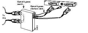
The FDDI SBus dual attachment adapter has a connector for an optical bypass switch. The six-pin mini-DIN connector is compatible with most optical bypass switches. See the appendix, "Cabling and Pinout Information," for bypass connector pinout information.
You can connect an optical bypass switch to the adapter to maintain connectivity to the FDDI ring. If a station enters a fault condition or is powered down or rebooted, the ring will not wrap if a bypass switch is present on the faulty station. When activated, a bypass switch removes a nonfunctioning dual attachment adapter from the ring.
 | Warning Invisible laser radiation may be emitted from the aperture ports of the single-mode FDDI card when no cable is connected. Avoid exposure and do not stare into open apertures. Following is an example of the warning label that appears on the product. (To see translated versions of this warning, refer to the section, "Invisible Laser Radiation Warning" in the appendix "Translated Safety Warnings.") |

The following figure shows how the bypass switch connects to the network and adapters.

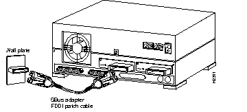
If you have an FDDI adapter, connect it to the network as follows:
Step 1 Connect one end of the MIC cable to the SBus adapter port as shown in Figure 4-3. The SPARCstation uses an IPC or IPX connection.

Step 2 Connect the other end of the cable to an FDDI network outlet.
Step 3 Verify that your adapter is connected to the concentrator and that the concentrator is plugged in and connected to the network.
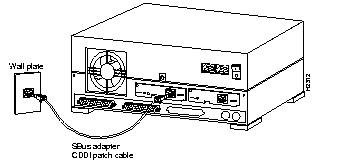
If you have a CDDI SBus adapter, connect it to the network as follows:
Step 1 Connect the end of the cable with the RJ-45 connector (supplied with your adapter) to the SBus adapter port as shown in Figure 4-4. The SPARCstation uses an IPC or IPX connection.

Step 2 Connect the other end of the cable to a CDDI network outlet.
Step 3 Verify that your adapter is connected to the concentrator and that the concentrator is plugged in and connected to the network.
To start up the system, turn ON the power switches in the following order:
To verify proper operation of the SBus adapter, apply power to the workstation and check the adapter LEDs.
The status LED shows the adapter's status. If this LED is on, the adapter has passed its internal diagnostics. This LED must be on for the adapter to function properly.
If the LED is not on, the SBus adapter has failed a critical diagnostic self-test. Run the FDDI status utility (see the appendix "Using the FDDI Status Utility") to determine the cause of the failure, and call the Cisco Technical Assistance Center.
Verify connection to the CDDI/FDDI ring by observing the ringop LED.
In a single attachment configuration the ringop LED monitors ring operation. If this LED is on, the adapter is connected to the CDDI/FDDI ring.
In a dual attachment configuration, the ringop LEDs on the dual attachment board work together to provide a visual indication of the state of your network. The ringop LED information in Table 4-1 will help you determine if your network is functioning properly.
| Ringop B1 Off | Ringop B1 Green | Ringop B1 Orange | |
|---|---|---|---|
| Ringop A2 Off | Ring is not operational. | Station is in WRAP_B. Ring is an operational SAS. RING A is not a connected DAS. | Ring is not operational. The station connected to PHY B is attempting to connect, but has failed. |
| Ringop A2 Green | Station is in WRAP_A. RING B is not connected. | Station is in THRU mode. Ring is operational. | Station is in WRAP_A. The station connected to PHY B is attempting to connect, but has failed. |
| Ringop A2 Orange | Ring is not operational. Station connected to PHY A is attempting to connect, but has failed. | Station is in WRAP_B. Station connected to PHY A is attempting to connect, but has failed. This is normal if the station is dual homed. | Ring is not operational. Stations connected to PHY A and PHY B are attempting to connect, but have failed. |
|
|