|
|

This chapter provides instructions for installing the workgroup CDDI/FDDI EISA PC adapters and the dual attachment optional adapter in your EISA PC.
An overview of the installation procedures follows:
The FDDI dual attachment adapter and FDDI dual attachment option are shipped with a small key on the media interface connector (MIC) identifying the port as an A port.
To remove the MIC key on the main adapter board proceed as follows:
Step 1 Use a pointed object, such as a pencil, to press on the tab as shown in Figure 3-1.
Step 2 Pull out the S (slave) key designating this as a single attachment adapter. (See Figure 3-1.)
Step 3 Insert the B key in the slot until it clicks into place to change this adapter to dual attachment configuration.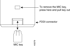
 | Warning Make sure that your workstation is powered down before beginning this procedure to avoid electrical shock. |
Step 1 Remove the workstation top cover and locate an available-bus master EISA slot. If you are also installing the dual attachment option adapter, locate two adjacent slots.
Step 2 Remove the metal protector plate from the desired slot on the back panel of the workstation.
Step 3 Follow the instructions supplied with your workstation to install the adapter.
Figure 3-2 shows the single attachment adapter and dual attachment option adapter with the ribbon cable attached (faceplate not shown).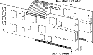
Step 4 If you are using the single attachment or single board dual attachment option configuration, proceed to step 7. If you are installing the dual attachment option adapter, proceed to the next step.
Step 5 To install the dual attachment option adapter, attach the ribbon cable to the connector on the main board before you insert the adapter into the computer. Be careful not to bend the pins on the adapter.
Step 6 Attach the other end of the ribbon cable to the connector on the dual attachment option adapter. Do not twist the cable. Be careful not to bend the connector pins on the adapter.
Step 7 Insert the dual attachment option adapter into the slot adjacent to the EISA PC single-attachment adapter. You do not need to configure this board.
Step 8 Replace the cover.
After you install the EISA PC adapter, you must configure the adapter base address and interrupt number.
| Warning Replace the top cover on the workstation before powering up the workstation. Failure to do so may result in personal injury and system damage. |
To configure the EISA slot, proceed as follows:
Step 1 Insert the EISA configuration utility disk, supplied with your PC, into the floppy drive.
Step 2 Apply power to the PC.
Step 3 Boot up the PC. The power-on test should report a configuration mismatch and prompt you to start the EISA configuration utility.
Step 4 Run the EISA configuration utility by following the instructions in your EISA PC documentation to add the workgroup adapter configuration file (!CRS320x.CFG) supplied on the workgroup EISA PC Driver disk. The configuration utility automatically assigns a nonconflicting memory base address and interrupt request (IRQ) number to the adapter.
 | Caution ISA cards in an EISA PC may use a conflicting memory address or interrupt line, which is not visible in the EISA configuration. After you run the EISA configuration utility, check the resources used by ISA cards in your EISA PC. Check the values used against the base address and IRQ assigned by the EISA configuration utility. An address or IRQ conflict may cause your system to hang or crash as soon as the adapter driver is loaded. |
Step 5 Record the slot number of the adapter card. You will need this information when you install the network adapter driver.
To connect the EISA PC adapter to the network proceed as follows:
Step 1 Connect one end of the cable to the EISA PC adapter port.
Step 2 Connect the other end of the cable to an CDDI or FDDI network outlet.
Step 3 Make sure the adapter is connected to the concentrator and that the concentrator is plugged in and connected to the network. If a concentrator or station is connected to the other end of the cable, the RINGOP LED should appear green when the PC is powered on.
You can connect an optical bypass switch connector to the dual attachment adapter to maintain connectivity to the FDDI ring. (For additional information see "Optical Bypass Switch Connector Pinout Information.") If a station enters a fault condition or is powered down or rebooted, the ring will not wrap if a bypass switch is present on the faulty station.
Figure 3-3 shows how the bypass switch connects to the network and adapters.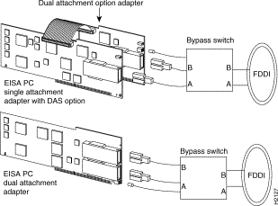
To make sure the workgroup EISA PC adapter is working properly, plug in power to the workstation and check the LEDs on the adapters.
If the LED is red, the EISA PC adapter has failed a critical diagnostic self-test. After you install the network driver, if the LED is still red, run the FDDI Status utility to determine the cause of the failure, then call a technical support representative. (For additional information, see "Using the FDDI Status Utility.")
The RINGOP LED monitors ring operation.
In a dual attachment configuration, the RINGOP LEDs work together to provide a visual indication of the state of your network. Use the RINGOP LED information in Table 3-1 to help determine whether your network is functioning properly.
| RINGOP B2 - Off | RINGOP B2 - Green | RINGOP B2 - Orange | |
|---|---|---|---|
| RINGOP A1 - Off | Ring is not operational. | Station is in WRAP_B. Ring is operational SAS. RING A is not connected DAS. | Ring is not operational. The station connected to PHY B is attempting to connect, but has failed. |
| RINGOP A1 - Green | Station is in WRAP_A. RING B is not connected. | Station is in THRU mode. Ring is operational. | Station is in WRAP_A. The station connected to PHY B is attempting to connect, but has failed. |
| RINGOP A1 - Orange | Ring is not operational. The station connected to PHY A is attempting to connect, but has failed. | Station is in WRAP_B. The station connected to PHY A is attempting to connect, but has failed. This is normal if the station is dual-homed. | Ring is not operational. The stations connected to PHYs A and B are attempting to connect, but have failed. |
![]()
![]()
![]()
![]()
![]()
![]()
![]()
![]()
Posted: Fri Sep 27 08:09:23 PDT 2002
All contents are Copyright © 1992--2002 Cisco Systems, Inc. All rights reserved.
Important Notices and Privacy Statement.