|
|

Table Of Contents
Cabling the Cisco uBR10-MC5X20S/U/H Cable Interface Line Card with Universal Cable Holder—UCH1
Quick Start Guide
Is Cisco documentation helpful? Click here or go to http://forums.cisco.com/eforum/servlet/viewsflash?cmd=showform&pollid=rtgdoc01!rtgdoc to give us your feedback.
Cabling the Cisco uBR10-MC5X20S/U/H Cable Interface Line Card with Universal Cable Holder—UCH1
Warning
Only trained and qualified personnel should be allowed to install, replace, or service this equipment.
Caution
1 Feature Description
The Cisco uBR10-MC5X20S, U and H cable interface line cards use 75-ohm precision video coax cables and 75-ohm MCX connectors to connect to the CMTS.
This document describes how to install and remove cables and the first generation universal cable holder (UCH1).
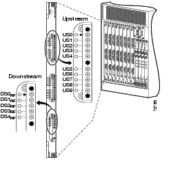
Figure 1 shows the cards in a Cisco uBR10012 router.
Figure 1 Cisco uBR10-MC5X20S/U/H Cards
The cables come in kits that consist of cable sets and spare F connectors.
The MC5X20 dual-shielded cable kit includes:
•
•
•
The MC5X20 quad-shielded cable kit includes:
•
•
The cable kits do not contain the universal cable holders; however, the UCH is available with line card accessory kits and spare cards. Or, the UCH2 is available as a spare.
Note
Tools required for cable installation include:
•
•
Also see " Tool Manufacturers and Part Numbers."
2 Installing the Cables
The UCH must be used for all Cisco uBR10-
MC5X20S/U/H line card cable connections. Failure to use the UCH may cause permanent damage to the line card connectors and result in low or no RF output.
Caution
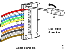
Step 1
Figure 2 Removing the Cable Clamp Bar
Step 2
Caution
Table 1 Port—Dual/Quad-Shielded Cable Colors
Table 2 Port—Legacy 5-Color Quad-Shielded Cable Colors
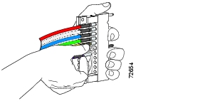
Step 3
Caution
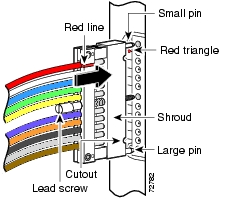
Figure 3 Inserting a Cable in the UCH1
Step 4
Step 5
Step 6
3 Installing the UCH
After the cables are installed in the UCH, follow these steps to prevent ESD damage to the line card.
Note
Step 1
Step 2
Step 3
Step 4
Figure 4 Installing the UCH
Step 5
Step 6
Step 7
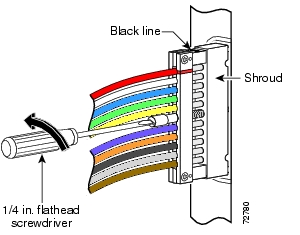
Caution
The UCH1 is fully engaged when the retractable shroud is aligned with the black lines. See Figure 5.
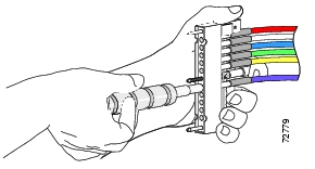
4 Removing the UCH
Step 1
Step 2
Step 3
Note
Figure 5 Removing the UCH
5 Removing the Cables
Step 1
Caution
Step 2
Step 3
Step 4
Figure 6 Using the Cable Extraction Tool
6 Troubleshooting
Check the following:
1.
2.
3.
If downstream RF power measurements are made, use these ESD precautions to prevent damage to the product:
1.
2.
3.
4.
Contact Cisco TAC for further information:
Tool Manufacturers and Part Numbers
7 Related Documentation
•
http://www.cisco.com/univercd/cc/td/doc/
product/cable/ubr10k/ubr10012/frus/
index.htm•
![]()
![]()
![]()
![]()
![]()
![]()
![]()
![]()
Posted: Thu Oct 25 13:43:40 PDT 2007
All contents are Copyright © 1992--2007 Cisco Systems, Inc. All rights reserved.
Important Notices and Privacy Statement.