cc/td/doc/product/cable/ubr10k/ubr10012
hometocprevnextglossaryfeedbacksearchhelp
PDF

Table Of Contents

Upgrading to the Half-Height Gigabit Ethernet Line Card for the Cisco uBR10012 Universal Broadband Router
(Note: this document does not apply to Cisco 10000 ESR routers)

Overview

Restrictions

Upgrading to the HHGE

Remove the FHGE

Install the Slot Splitter Card

Install the HHGE

Installing the SFP GBIC

Remove the GBIC

Install the GBIC

Configuring the HHGE

Troubleshooting

Technical Specifications

Related Documentation


Quick Start Guide

Upgrading to the Half-Height Gigabit Ethernet Line Card for the Cisco uBR10012 Universal Broadband Router
(Note: this document does not apply to Cisco 10000 ESR routers)


Warning Only trained and qualified personnel should be allowed to install, replace, or service this equipment. Statement 1030


1 Overview

This quick start guide provides information about upgrading from a full-height Gigabit Ethernet line card (FHGE) to a half-height Gigabit Ethernet (HHGE) line card in the Cisco uBR10012 universal broadband router.

The Small Form-factor Pluggable (SFP) gigabit interface converter (GBIC) modules used with the HHGE line card, support gigabit Ethernet interface types: SX, LX/LH, and ZX. GBICs are OIR compatible and can be changed or upgraded at any time.


Caution Only SFP GBIC modules purchased from Cisco work with the gigabit Ethernet line card software.

Restrictions

Review these restrictions before upgrading to the HHGE line card in the Cisco uBR10012 router.

Cisco IOS software release 12.3(13)BC or later IOS release must be installed

Performance Routing Engine 2 (PRE2) modules must be installed in the router

The HHGE line card is installed in slot 3 (3/0/0, 3/1/0) or slot 4(4/0/0, 4/1/0) only. Installing the line card in slot 1 or slot 2 causes those slots to shut down.

2 Upgrading to the HHGE

Follow these steps when upgrading from a FHGE line card to a HHGE line card.


Caution Make sure you are properly grounded.

Remove the FHGE


Step 1 Verify that traffic is passing through slot 3 and slot 4.

Step 2 Administratively shut down the card in slot 3. Traffic reroutes through slot 4.

Step 3 Remove the FHGE line card in slot 3.


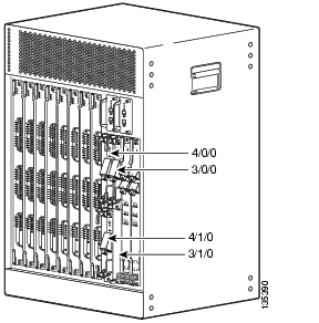
Figure 1 Cisco uBR10012 Router HHGE Slots

Install the Slot Splitter Card

The slot splitter card must be installed in slot 3 or slot 4 in the Cisco uBR10012 router before HHGE line cards can be installed.


Step 1 Install the slot splitter card in slot 3.

a. Grasp the front of the card with one hand and place your other hand under the slot splitter.

a. Align the slot splitter with the upper and lower card guides in the chassis, then slide it into the chassis until the front is flush with the chassis.

Step 2 Tighten the upper and lower captive screws to secure the slot splitter card in the chassis.


Install the HHGE

The HHGE card is installed in the slot splitter after the slot splitter is installed in the chassis. Install in slot 3 (3/0/0, 3/1/0) and slot 4 (4/0/0, 4/1/0) only.


Step 1 Grasp the faceplate with one hand and place your other hand under the card carrier (to support the weight of the card).

Step 2 Align the upper and lower edges of the card with the upper and lower guides in the slot splitter.

Step 3 Slide the card half-way into the splitter.

Step 4 Be sure that the ejectors are open and that the captive screws on the card are aligned with the holes in the slot splitter.


Caution If the captive screws are not properly aligned and inserted into the slot splitter, the card will not seat properly in the backplane connectors.

Step 5 Slide the card into the chassis until you feel the card seat in the backplane connectors.

Step 6 Simultaneously close both ejector levers (until they are parallel to the faceplate). The card cycles through a power-on self-test.

Step 7 Tighten the captive screws to secure the HHGE card in the slot splitter.

Step 8 Repeat the entire procedure for slot 4.


Tip To ensure that there is adequate space for additional cards, tighten the captive screws on each newly installed card before inserting additional cards.


3 Installing the SFP GBIC


Note GBICs are OIR components. However the interface shuts down when one is replaced.


Remove the GBIC


Step 1 Ensure you are properly grounded.

Step 2 Disconnect the fiber-optic cable from the SFP GBIC (if necessary). Note which connector plug is the TX and which is the RX for reattachment.

Step 3 Insert a dust plug into the optical port of the GBIC.

Step 4 Unlock and remove the GBIC.

a. Mylar Tab GBIC—Gently, but firmly pull the plastic tab to free the locking pin and remove the GBIC.

b. Bale Clasp GBIC—Open the clasp to release the locking pin and remove the GBIC.

Step 5 Place the GBIC in an antistatic bag or other protective environment.


Install the GBIC


Step 1 Gently insert the GBIC into the HHGE port until the edge connector is fully seated in the connector. You hear a click as the pin on the bottom of the GBIC snaps into place.

Step 2 Remove the dust plug from the GBIC.

Step 3 Clean both the cable and the GBIC fiber-optic connections. See Related Documentation for the location of fiber-optic cleaning information.

Step 4 Plug the LC-type cable into the port.

Step 5 Make sure that you have the TX and RX plugs in the correct port.


4 Configuring the HHGE

For configuration information, please refer to Configuring the Half-Height Gigabit Ethernet Line Card for the Cisco uBR10012 Universal Broadband Router

If you are replacing an HHGE card with another HHGE card, the system automatically downloads the necessary configuration information from the PRE 2. Interfaces that were configured in an up state in the previous card are recognized as up in the replacement card.

5 Troubleshooting

If an error message appears on the console every time the line card requests an image download, the HHGE line card is inserted in slot 1 or slot 2.

If the PRE2 software shuts down the card, the reset line is asserted and the running configuration is updated with this slot in the shutdown state, and the HHGE line card is inserted in slot 1 or slot 2.

1. Place the HHGE in slot 3 (3/0/0, 3/1/0) or slot 4 (4/0/0, 4/1/0).

2. Use the no hardware module shut command to reset the slot.

no hardware 3/0/0 shut

LEDs

FAIL (yellow)—This LED lights during portions of the POST (Power-On Self Test), but remains off after the POST on a properly working line card. If the line card fails during operation, this LED lights and an alarm event occurs.

FAIL LED blinks during the following SFP faults:

Non-Cisco SFP GBIC inserted

Non-gigabit Ethernet SFP GBIC is inserted

Hardware problem with a valid SFP GBIC

LINK (green)—When the LED is on, a carrier signal exists. If negotiation is enabled (at both ends), it indicates successful completion and the port can pass traffic. This LED can also be on if the line card is in internal loopback. When the LED is off, no carrier signal is detected, negotiation failed, or the port is administratively down.

RX (green)—When the LED is on, the line card is receiving packets. When the LED is off, the line card is not receiving packets.

TX (green)—When the LED is on, the line card is transmitting packets. When this LED is off, the line card is not transmitting packets.

1

FAIL LED

3

TX LED

2

RX LED

4

LINK LED


6 Technical Specifications

Table 1 Part Numbers

Description
Part Number

HHGE line card

ESR-HH-1GE

Slot splitter card

ESR-HH-CARRIER

Half-height slot cover

ESR-HH-COVER

Full height slot cover

ESR-COVER

1000BASE-SX

SFP-GE-S

1000BASE-LX/LH

SFP-GE-L

1000BASE-ZX

GLC-ZX-SM


Table 2 Specifications

Description

Power consumption: 15.98 W

1000BASE SX GBIC

Power budget: 7.5 dB
Transmit power: -9.5 to 0 dBm
Receive power: -17 to 0  dBm

1000BASE LX/LH GBIC

Power budget: 7.5 dB (multimode fiber), 8 dB (single mode)
Transmit power: -11.5  to -3 dBm (multimode fiber), -11 to -3 dBm (single mode)
Receive power: -19  to -3 dBm (multimode and single mode fiber)

1000BASE ZX GBIC

Power budget: 23 dB
Transmit power: 0 dBm to 4.77 dBm
Receive power: -23 dBm to 0 dBm


7 Related Documentation

Configuring the Half-Height Gigabit Ethernet Line Card for the Cisco uBR10012 Universal Broadband Router

http://www.cisco.com/univercd/cc/td/doc/product/cable/ubr10k/ubr10012/ub10ksw/index.htm

Cisco uBR10012 Universal Broadband Router Half-Height Gigabit Ethernet Line Card Installation

http://www.cisco.com/univercd/cc/td/doc/product/cable/ubr10k/ubr10012/frus/index.htm

Cisco uBR10000 Series Universal Broadband Router Release Notes

http://www.cisco.com/univercd/cc/td/doc/product/cable/ubr10k/ub10krns/index.htm

Inspection and Cleaning Procedures for Fiber-Optic Connections

http://www.cisco.com/warp/public/127/
cleanfiber2.html


hometocprevnextglossaryfeedbacksearchhelp

Posted: Mon Apr 3 15:29:53 PDT 2006
All contents are Copyright © 1992--2006 Cisco Systems, Inc. All rights reserved.
Important Notices and Privacy Statement.