|
|

Table Of Contents
UNIX Server Systems with Solaris
UNIX Server Systems with Linux
UNIX Client Machine with Solaris
UNIX Client Machine with Linux
PC Client Machine with Windows
Enhanced Support for Operating Systems and Web Server Applications
Minimum Cisco Universal Broadband Router and Cisco IOS Requirements
Installing, Downloading, and Upgrading CBT 3.3
Using TCP Ports for CBT 3.3 Upgrade and Operation
Installing and Starting CiscoView on Solaris
Installing and Starting CBT on Windows
Installing and Starting CBT on Linux
Requirements for Installing Daylight Savings Time (DST) Operating System Patches
Configuring Cisco Broadband Troubleshooter
Configuring the Cisco CMTS to Use the CBT Spectrum Management Tools
Configuring the Java Runtime Environment
(Optional) Configuring CiscoView
(Optional) Using Subscriber Traffic Management with CBT 3.3
Workflow of Administrator and RF Technician Tasks
Setting Up CBT with a Password, Users, and Data for Routers and Subscribers
Changing the Administrator Password
Disabling or Enabling Password Text Display
Setting Parameters in .INI Files
Parameters in the CONFIGS.INI File
Parameters in the POLLER.INI File
Parameters in the SPECTRUM.INI File
Parameters in the GUNSLINGER.INI File
Retrieving Subscriber or Provisioning Data by Using an External Interface
Retrieving Data with an Application on an HTTP Server
Retrieving Subscriber Data from the Local Database
Retrieving Provisioning Data from the Local Database
Getting Summary Information and a Detailed Real-Time Status Report for a Modem
Getting Summary Information on a Modem
Getting a Detailed Real-Time Status Report for a Modem
Showing and Configuring the Flap List Analysis
Showing the Flap List Analysis
Scheduling the Flap List Analysis
Setting Parameters for the Flap List
Using the Spectrum Management Tools
Sorting Support in the CBT 3.3 Graphical User Interface
Using Auto-Select in the Trace Window
Analyzing the Carrier-to-Noise Ratio
Working with Spectrum Management Clients
Enabling Instantaneous CPU Assessment for Spectrum Polling
Administrative Tasks for CBT 3.3
Mapping Hostnames from Applet to Servlet
Configuring Administrative Parameters for Spectrum Analysis
Troubleshooting Tips for CBT 3.3
Troubleshooting Continuous Sweep Spectrum Operation in CBT 3.3
Changing Server Ports in XML Script
Saving System Message Logs for Troubleshooting
Verifying Installation Status on the CBT 3.3 Server
Troubleshooting Poller Problems
Uninstalling Cisco Broadband Troubleshooter
Sample Code for Application Program Interfaces
Shell Script for Retrieving Subscriber or Provisioning Information
Java Code for Retrieving Subscriber or Provisioning Information
Product Overview
Multiple service operators (MSOs) and cable companies provide subscribers with a variety of cable services such as TV, video on demand, data, and voice telephony. Cisco Broadband Troubleshooter Release 3.3 (CBT 3.3) is a troubleshooting tool designed for network administrators and radio frequency (RF) technicians at a multiple service operator site. The network administrator and the RF technician use Cisco Broadband Troubleshooter Release 3.3 (CBT 3.3) to monitor and resolve RF problems in the MSO cable plant.
CBT 3.3 introduces several enhancements that make it more powerful than any prior release. This document describes configuration and operation procedures for CBT 3.3, with updates to cover newly supported operating systems, feature functions, MIB interoperability, and graphical user interface (GUI) enhancements.
Refer to the Release Notes for Cisco Broadband Troubleshooter Release 3.3 for itemized information and features introduced in CBT 3.3.
CBT 3.3 provides the following general functionality:
•
Provides summary statistics for each upstream port attached to a cable modem termination system (CMTS).
•
–
–
–
–
•
•
–
–
–
•
–
–
–
–
–
–
•
–
–
–
•
•
Note
This release supports Cisco Broadband Troubleshooter installed on a server that is running the Solaris, Linux, or Windows operating systems.
System Requirements
This section lists the system requirements for:
•
–
–
•
•
CBT 3.3 generally supports these OS platforms:
•
•
•
•
This section provides additional system-level information in these topics:
•
•
•
•
•
•
•
•
Windows Systems
Windows systems supported include Windows 2000, Windows XP, and Windows XP Workstation with Linux Enterprise Edition.
UNIX Server Systems with Solaris
The following environment supports 10 Cisco CMTS headend systems:
•
•
•
•
•
The following environment supports 50 or 100 Cisco CMTS headend systems:
•
•
•
•
•
The following environment supports 500 Cisco CMTS headend systems:
•
•
•
•
•
UNIX Server Systems with Linux
The following environment supports 10, 50, or 100 Cisco CMTS headend systems:
•
•
•
•
PC Server Systems for Windows
The following environment supports 10, 50, or 100 Cisco CMTS headend systems:
•
•
•
•
UNIX Client Machine with Solaris
The following client system supports CBT 3.3 on Solaris:
•
•
•
UNIX Client Machine with Linux
The following client system supports CBT 3.3 with Linux:
•
•
•
PC Client Machine with Windows
The following client system supports CBT 3.3 with Windows:
•
•
•
Enhanced Support for Operating Systems and Web Server Applications
CBT 3.3 offers enhanced support for the following operating systems and web server software environments:
•
•
•
•
•
•
DST Patch for Operating Systems
CBT 3.3 introduces the operating system patch associated with recent Daylight Savings Time (DST) requirements.
Java Runtime Environment in CBT 3.3
CBT 3.2 supported Java Runtime Environment (JRE) through JRE version 1.4.1. CBT 3.3 now comes with Java J2SE Runtime Environment 5.0 embedded in it.
We also recommend upgrading to JRE 5.0 on the client side to benefit from the latest enhancements, caveat resolutions, and security features, specifically for the Solaris platform.
Linux Operating System
CBT 3.3 introduces support for Red Hat Enterprise Linux products and the Red Hat desktop operating system. We recommend upgrading from prior Linux versions, such as Linux Red Hat 7, 8, and 9, as these prior versions have reached the end of their support lifetimes.
Solaris Operating System
CBT 3.3 introduces support for the Solaris operating system through Solaris 10. The prior CBT 3.2 supported Solaris through Solaris 8. Cisco recommends upgrade to Solaris 10 for use with CBT 3.3 to gain support for high-performance server machines that require Solaris 10, and related CBT 3.3 enhancements.
Tomcat Application Server
CBT 3.3 introduces upgraded support for the Tomcat Application Server. In CBT 3.2, support was limited to jakarta-tomcat-4.1. CBT 3.3 extends support to include apache-tomcat-5.5.15. The latest Tomcat version introduces scalability and reliability enhancements supported in CBT 3.3, performance optimizations, and reduced garbage collection.
CBT 3.3 includes the latest Tomcat application upgrade, and it is not necessary to download this application server separate from CBT 3.3 installation.
Windows Operating System
CBT 3.3 supports the latest Windows Operating Systems from Microsoft, such as Windows 2000 or Windows XP. No additional Windows upgrades are required for CBT 3.3.
Minimum Cisco Universal Broadband Router and Cisco IOS Requirements
You can use Cisco Broadband Troubleshooter with the following universal broadband routers (uBRs):
•
•
•
On these routers, CBT 3.3 supports the following Cisco IOS releases:
•
Minimum Cisco Universal Broadband Router and Cisco IOS Requirements to Use Spectrum Management Features in CBT
To use the spectrum management features that Cisco Broadband Troubleshooter provides, you must have the following:
•
•
For more information, see "Configuring the Cisco CMTS to Use the CBT Spectrum Management Tools" section.
Enabling SNMP on Routers
You must enable SNMP on the routers by entering the following commands:
Router# configure terminalRouter(config)# snmp-server community public RORouter(config)# snmp-server community private RW
Note
Using SNMP MIBs in Cisco CBT 3.3
Cisco Broadband Troubleshooter Release 3.3 (CBT3.3) uses the following SNMP MIBs with Cisco IOS Release 12.3(21)BC and later releases:
•
•
•
•
•
•
•
•
–
–
–
–
•
•
•
–
–
–
–
–
–
When extracting the downloaded CBT 3.3 file, these MIBs are placed by default in the following path:
<CBT Install Directory>/httpServer/webapps/ROOT/WEB-INF/mibs
Note
Generally, all read and create objects in the ccsSpectrumRequestTable and ccsSNRRequestTable can be set with spectrum management tools in CBT 3.3. These objects require a WRITE community string:
•
–
–
–
–
–
–
–
•
–
–
–
For additional MIBs information for the Cisco CMTS, refer to the following resources on Cisco.com:
•
http://www.cisco.com/univercd/cc/td/doc/product/cable/cmtsmib/
•
http://www.cisco.com/pcgi-bin/Support/Mibbrowser/unity.pl
Installing, Downloading, and Upgrading CBT 3.3
Use the following steps to download and to install CBT 3.3 on a system with the Linux, Solaris, or Windows operating systems. This section contains the following topics:
•
•
•
•
•
Using TCP Ports for CBT 3.3 Upgrade and Operation
Note
We recommend ports other than 8005, 8080, 9080, 9443, or 9082.
The following are the default ports used by CBT 3.3:
•
•
•
•
•
•
CBT 3.3 uses the following port ranges for spectrum operations. Spectrum events such as Trace Window, Spectrogram, CNR Trending, and the Generic Query use a specified range of port numbers for operation.
•
•
•
•
CBT 3.3 Download and Upgrade
Step 1
•
http://www.cisco.com/cgi-bin/tablebuild.pl/cbt
•
–
–
–
–
Step 2
•
a.
b.
c.
•
a.
b.
c.
Uninstalling Prior CBT Releases
Step 3
•
•
•
–
–
Step 4
•
•
•
–
–
Note
Step 5
•
•
www.cisco.com/go/license/public
Note
Demonstration copies are available either by way of the Internet, or as an ordered accessory for a universal broadband router product.
The copies supplied with a universal broadband router product include a demo license certificate with a PAK key.
The copy available from the Internet uses a registration page where the PAK key is e-mailed to you.
Step 6
•
1.
2.
3.
•
1.
2.
3.
•
1.
2.
3.
Note
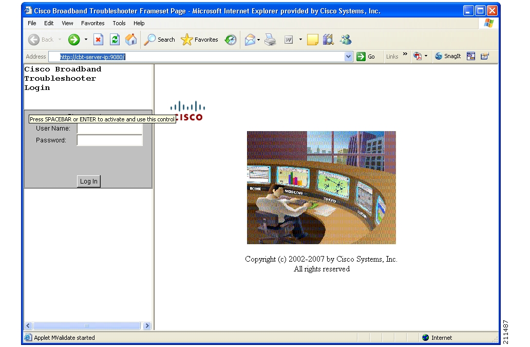
Figure 1 CBT Log In Window
Installing and Starting CiscoView on Solaris
Note
Step 1
Step 2
Step 3
•
•
mount CD-ROM device /cdrom
Note
Step 4
cd /cdrom/cdrom0/solaris/cv./setup.shThe CBT server is now running.
Step 5
umount /cdrom
Note
Step 6
ejectInstalling and Starting CBT on Windows
DETAILED STEPS
Step 1
Step 2
Step 3
The CBT server is now running.
Step 4
Start > Programs > Cisco Broadband Troubleshooter > Start Troubleshooter
or
To access CBT by using a browser, open the browser and enter:
http://CBT server IP address:9080/
Note
Step 5
Step 6
Start > Programs > Cisco Broadband Troubleshooter > Stop Troubleshooter
Installing and Starting CBT on Linux
Step 1
Step 2
Step 3
Step 4
./installThe CBT server is now running.
Step 5
~ /opt/CSCOcbt/bin./start_appor
To access CBT by using a browser, open the browser and enter:
http://CBT server IP address:9080/
Note
Step 6
Step 7
~/opt/CSCOcbt/bin./stop_appRequirements for Installing Daylight Savings Time (DST) Operating System Patches
CBT 3.3 requires that the latest operating system patches be installed for all platforms supported by CBT 3.3. Refer to the "Enhanced Support for Operating Systems and Web Server Applications" section for additional information about supported platforms.
JRE OS-Level Requirements
CBT 3.3 supports the latest Java Runtime Environment (JRE 5.0) platform. However, the network administrator must ensure that all OS-level patches are installed to avoid system problems with CBT 3.3. This section describes patch requirements according to platform.
•
–
•
–
–
•
–
http://sunsolve.sun.com/search/document.do?assetkey=1-26-102178-1
Configuring Cisco Broadband Troubleshooter
The following configuration procedures are required for using Cisco Broadband Troubleshooter Release 3.3:
•
•
The following configuration procedures are optional for CBT 3.3:
•
•
Configuring the Cisco CMTS to Use the CBT Spectrum Management Tools
Cisco Broadband Troubleshooter Release 3.3 provides spectrum management functionality, which is generated by Digital Signal Processing (DSP) in the Cisco uBR-MC16S Spectrum Management Line Card on the CMTS. The CBT spectrum management tools require Cisco IOS Release 12.2(15)BC1. For more information, see the "Minimum Cisco Universal Broadband Router and Cisco IOS Requirements" section.
Before using the spectrum management features in Cisco Broadband Troubleshooter, you must complete spectrum management configuration tasks on the CMTS. These configurations are outside the scope of Cisco Broadband Troubleshooter.
For more information, refer to the following document on Cisco.com:
•
Configuring the Java Runtime Environment
This section describes Java Runtime Environment (JRE) requirements and procedures through JRE 5.0, but includes procedures for earlier JRE platforms.
JRE 5 OS-Level Requirements
CBT 3.3 supports the latest JRE 5.0 platform. However, the network administrator must ensure that all OS-level patches are installed to avoid system problems with CBT 3.3. This section describes patch requirements according to platform. Refer also to the "JRE OS-Level Requirements" section.
The Sun JRE 5.0 is a plug-in that must be installed in the client browser. Cisco Broadband Troubleshooter detects if JRE 5.0 is installed in the browser. This section provides directions to install JRE 5.0 in the browsers supported by each platform.
Installing JRE 5.0 in Microsoft Internet Explorer on the Windows Platform
If JRE 5.0 is not installed in Internet Explorer on the Windows platform, the installation is automatic.
Installing JRE 5.0 in Netscape Navigator on the Windows Platform
If JRE 5.0 is not installed in Navigator on the Windows platform, refer to the following location:
http://java.sun.com/javase/downloads/index_jdk5.jsp
Perform the following steps to install JRE 5.0 in Netscape Navigator on the Windows platform:
Step 1
Note
Step 2
Start > Run > JRE5.0_07InstallationDirectory \jre-1_5_0_06-windows-i586-p.exe
Step 3
Step 4
Installing JRE 5.0 in Netscape Navigator on the Solaris Platform
If JRE 5.0 is not installed in Navigator on the Windows platform, refer to the following location:
http://java.sun.com/javase/downloads/index_jdk5.jsp
Perform the following steps to install JRE 5.0 on the Solaris platform:
Step 1
Note
Step 2
jre-1_5_0_08-solaris-sparc.shStep 3
•
setenv NPX_PLUGIN_PATH JRE5.0InstallationDirectory/plugin/sparc/ns4
•
ln -s JRE5.0InstallationDirectory/plugin/sparc/ns610/libjavaplugin_oji.so Netscape7.0InstallationDirectory/plugins/libjavaplugin_oji.so
Step 4
Step 5
Installing JRE 5.0 in Netscape Navigator on the Linux Platform
If JRE 5.0 is not installed in Navigator on the Windows platform, refer to the following location:
http://java.sun.com/javase/downloads/index_jdk5.jsp
Perform the following steps to install JRE 5.0 in Netscape Navigator on the Linux platform:
Step 1
Note
Step 2
jre-1_5_0_08-linux-i586.binStep 3
•
setenv NPX_PLUGIN_PATH JRE5.0InstallationDirectory/plugin/i386/ns4•
ln -s JRE5.0_InstallationDirectory/plugin/i386/ns610/libjavaplugin_oji.so
Netscape7.0InstallationDirectory/plugins/libjavaplugin_oji.so
Step 4
Step 5
(Optional) Configuring CiscoView
CiscoView is a web-based device management application that provides dynamic status, monitoring, and configuration information for a range of Cisco internetworking products. CiscoView displays a physical view of a device chassis, with color-coding of modules and ports for at-a-glance status, and has two levels of capabilities:
•
•
For product information, refer to the following document on Cisco.com:
http://www.cisco.com/en/US/products/sw/cscowork/ps4565/index.html
You can launch CiscoView 5.x from CBT to monitor a device and get real-time information on it.
Perform the following steps to configure and launch CiscoView from CBT:
Step 1
Step 2
Step 3
Note
(Optional) Using Subscriber Traffic Management with CBT 3.3
To use the Subscriber Traffic Management (STM) feature of CBT 3.3, the cable qos enforce-rule command on the Cisco CMTS must be used with a QoS profile that is not created by the cable modem. Any in-use QoS profile, such as one created by a cable modem, can be turned into a management profile.
Note
Perform the following steps to create a management profile:
Reviewing the CBT Task Menu
This section describes the following components of the CBT Task Menu:
•
After you log on to CBT, the CBT 3.3 Task menu appears. See Figure 2:
Figure 2 CBT Task Menu
Above the menu, your user type is displayed. For more information on user types, see "User Types in CBT" section.
All tasks in CBT are divided into the following menus:
•
•
•
•
•
•
•
The following sections describe the tasks within each menu.
User Guide
The User Guide menu contains one task:
•
Configuration
The Configuration menu contains the following tasks:
•
•
•
•
•
•
•
•
•
•
Diagnostics
The Diagnostics menu contains the following tasks:
•
•
Hotline Tools
The Hotline Tools menu contains the following tasks:
•
•
•
•
•
Spectrum Tools
The Spectrum Tools menu contains the following tasks:
•
•
•
•
–
–
•
•
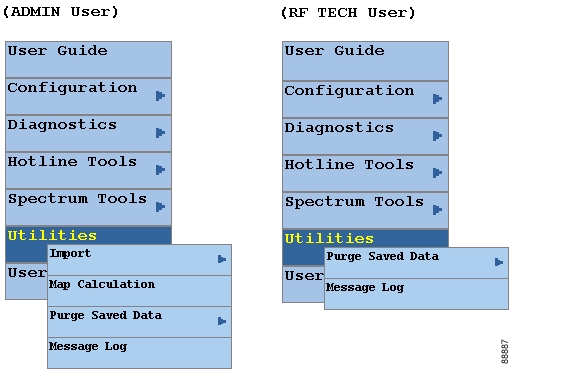
Utilities
The Utilities menu contains the following tasks:
•
–
–
•
•
–
–
•
User Log Out
The User Log Out menu contains one task:
•
User Types in CBT
The number of tasks you see in the CBT menu varies according to the type of user you are. There are two user types in CBT, each with access to different tasks:
•
•
–
–
In each other menu, the RFTECH user has access to all tasks.
Figure 3 Configuration Menus for ADMIN and RFTECH Users
Figure 4 Utilities Menus for ADMIN and RFTECH Users
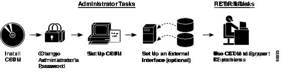
Workflow of Administrator and RF Technician Tasks
Figure 5 Administrator and RF Technician Tasks in CBT
Figure 5 illustrates a high-level workflow of tasks that each type of user, the administrator and the RF technician, performs in CBT.
Administrator Tasks
The first four tasks shown in Figure 5 are ones that only an administrator can perform.
•
•
•
–
–
–
•
–
–
Note
The remainder of this guide explains these tasks in greater detail.
RF Tech Tasks
The last task shown in Figure 5 is one that the RF technician performs:
•
–
–
–
–
Setting Up CBT with a Password, Users, and Data for Routers and Subscribers
This section describes the following important setup tasks that only a CBT administrator can perform:
•
•
•
Changing the Administrator Password
For security reasons, we recommend that you change the default password for the administrator. Perform the following steps to change the administrator password:
Step 1
http://CBT server IP address:9080/
Note
The Login dialog box appears, as shown in Figure 1.
Step 2
Step 3
Disabling or Enabling Password Text Display
CBT 3.3 enables you to display password text, or to disable password text display according to your needs. By default, this parameter is set to YES. If you set the corresponding parameter to NO , CBT does not display password text when the contents of the Password field is displayed.
Perform the following steps to disable or to enable password text display for one or more User Names. Restart of CBT 3.3 is required as the final step of configuring this change.
Step 1
•
•
Step 2
•
•
Step 3
Step 4
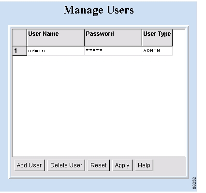
Adding Users
You add users in CBT by specifying the following information for a user:
•
•
•
Perform the following steps to add users in CBT:
Step 1
Step 2
Step 3
Figure 6 CBT Log In Window
Figure 7 Manage Users Dialog Box
Adding Router Information
You can add router information in CBT by using either of the following methods in the CMTS List option of the Configuration menu:
•
•
–
–
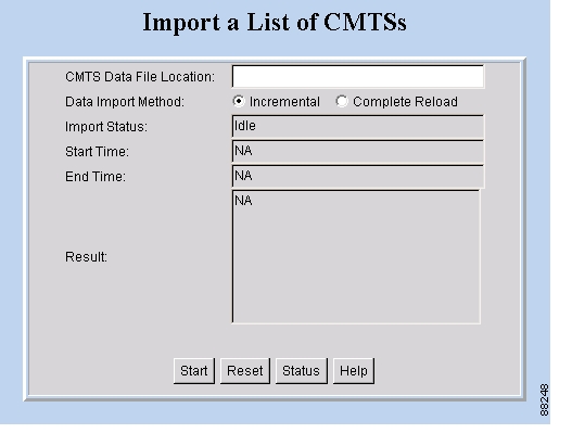
If you import an ASCII file, the file must contain 13 fields for each CMTS:
•
•
•
•
•
Each field must be separated by a comma (,). If you leave a field blank, use a comma as a placeholder for it.
The following example shows the ASCII file format and data for a Cisco CMTS in this format:
172.21.73.10,public,private,public,jdoe,nAda,nAda,nAda,yes,23,UserName,Password,yesPerform the following steps to add information about the Cisco uBR7100 series, Cisco uBR7200 series, and Cisco uBR10012 universal broadband router in CBT:
Step 1
Step 2
•
•
For a complete description of each field in the CMTS List dialog box, click Help.
Step 3
Tip
Note
Figure 8 Import a List of CMTSs Dialog Box
Adding Subscriber Information
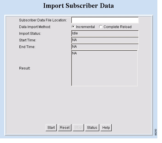
To add subscriber information in CBT, you import an ASCII text file that contains the subscriber information. A sample file is in the following locations:
•
•
For each subscriber, the ASCII text file must contain 12 fields. The following fields are typical, although only the first one is required:
1.
2.
3.
4.
5.
6.
7.
8.
9.
10.
11.
12.
Each field, including blank ones, must be separated with the pipe symbol |.
The following example shows the ASCIII file format data for a subscriber in this format:
000216d5a0cf|ID987654|JohnDoe|4085551212|175 West Tasman|San
Jose|CA|95134|USA|Gold|FiberNode_SanJose|Paid
Perform the following steps to add subscriber information to CBT:
Step 1
Step 2
Step 3
Figure 9 Import Subscriber Data Dialog Box
Setting Parameters in .INI Files
This section describes the parameters you set in three .INI files in CBT:
•
•
•
•
Note
This section contains the following topics relating to setting parameters in .INI files for CBT 3.3.
•
•
•
•
Parameters in the CONFIGS.INI File
In addition to specifying system-level parameters in the CONFIGS.INI file, you can also specify some of the parameters in the GUI.
Tip
This section describes parameters that you configure in the CONFIGS.INI file, which is in the following locations:
•
•
•
Note
Phone Number Format
The phoneLength parameter applies to Cisco Cable Diagnostic Manager only.
Modem Status Thresholds
When you view a status report for a cable modem, color-coding indicates the modem's status:
•
•
The following parameters set the thresholds that determine the boundaries for color-coding and must be configured in the CONFIGS.INI file:
•
•
•
•
•
upstreamXmitPowerFloor—This parameter determines the minimum upstream transmit power for a cable modem to show a functioning status. This measurement is expressed in decibels millivolt (dBmV). The default setting is 34, as shown below:
upstreamXmitPowerFloor=34
upstreamXmitPowerCeiling—This parameter determines the maximum upstream transmit power for a cable modem to show a functioning status. This measurement is expressed in decibels millivolt (dBmV). The default setting is 52, as shown below:
upstreamXmitPowerCeiling=52
downstreamSnrFloor—This parameter determines the minimum signal-to-noise (SNR) for a cable modem to show a functioning status. SNR is a measure of transmission quality, which is expressed by the ratio of good data (signal) to interference (noise) that is heard on a line. This ratio is measured in decibels (dB). A higher ratio indicates a better transmission quality. For example, 30 dB is better than 24 dB. The default setting is 30, as shown below:
downstreamSnrFloor=30
downstreamReceivePowerFloor—This parameter determines the minimum downstream receive power for a cable modem to show a functioning status. This measurement is expressed in decibels millivolt (dBmV). The default setting is 15, as shown below:
downstreamReceivePowerFloor=15
downstreamReceivePowerCeiling—This parameter determines the maximum downstream receive power for a cable modem to show a functioning status. This measurement is expressed in decibels millivolt (dBmV). The default setting is 5, as shown below:
downstreamReceivePowerCeiling=5
Southbound Interface Settings
These parameters apply to Cisco Cable Diagnostic Manager only:
SouthBoundExtIntf
SouthBoundExtIntfTimeout
Modem State Settings
These parameters apply to Cisco Cable Diagnostic Manager only:
ModemStateMaxLife
ModemStateMaxHash
Query Timeout
The administrator specifies external interface parameters to access subscriber and provisioning information. Most of these parameters are in the Set External Interfaces dialog box. However, you must configure the following external interface parameters in the CONFIGS.INI file.
SubscriberExtIntfTimeout—This parameter determines the maximum wait time before CBT times out during a query for subscriber information. This measurement is expressed in milliseconds (msecs). The default setting is 5000, which is equal to 5 seconds, as shown below:
SubscriberExtIntfTimeout=5000
ProvisionExtIntfTimeout—This parameter determines the maximum wait time before CBT times out during a query for provisioning information. This measurement is expressed in milliseconds (msecs). The default setting is 5000, which is equal to 5 seconds, as shown below:
ProvisionExtIntfTimeout=5000
Parameters in the POLLER.INI File
When it starts, the Poller accesses the POLLER.INI file, which is in the following locations:
•
•
Note
The Poller accesses POLLER.INI to gather the following configurable parameters:
•
•
•
•
•
•
•
maximumThread—This parameter determines the maximum number of different execution threads that can run simultaneously in the Poller. The valid range is 1 to 50. The default setting is 20, as shown below:
maximumThread=20
maximumDBConnection—This parameter determines the maximum number of CBT Sybase database connections the Poller uses to perform the polling operation. The valid range is 1 to 7. The default setting is 7, as shown below:
maximumDBConnection=7
SnmpTimeout—This parameter determines the number of seconds before the attempt to create the SNMP connection will reach a timeout or fail. The valid range is 1 to 3. The default setting is 2, as shown below:
SnmpTimeout=2
SnmpRetry—This parameter determines the number of times you want to try to create the SNMP connection. The valid range is 1 to 5. The default setting is 3, as shown below:
SnmpRetry=3
Debug—This parameter determines if debug messages are sent to the log file, which is in the following location:
/opt/CSCOcbt/logs/Poller.log
Valid values are true and false. The default setting is false, as shown below:
Debug=false
maximumAge—This parameter tells the Poller which outdated records to purge, based on the number of polling intervals that have occurred during which those records have not been updated. This measurement is expressed in polling intervals. A valid range is 1 to 7. The default setting is 2, as shown below:
maximumAge=2
PollerServerPort—This parameter sets the HTTP server port number where the Poll Manager listens to polling requests. The default setting is 8040:
PollerServerPort=8040
Note
Parameters in the SPECTRUM.INI File
The parameters you specify in the SPECTRUM.INI file affect the following spectrum management tools:
•
•
•
•
This section describes parameters that you configure in the SPECTRUM.INI file, which is in the following locations:
•
•
•
Note
The spectrum management tools access SPECTRUM.INI to gather the following configurable parameters:
•
•
•
•
•
•
•
•
CNRFloor—This parameter determines the lower threshold for the carrier-to-noise ratio that you see in the spectrum tools. CNR is a measure of transmission quality, which is expressed by the ratio of good data from the carrier to interference or noise that is heard on a line. A higher ratio indicates a better transmission quality. If the CNR is below this lower threshold, the value is highlighted in the color you specify in the CNRFloorColor parameter. This measurement is expressed in decibels (dB). Acceptable values range from -20 to 60 dB. If an unacceptable value is entered, the system default is used. The default setting is 20, as shown below:
CNRFloor=20
CNRCeiling—This parameter determines the upper threshold for the carrier-to-noise ratio that you see in the spectrum tools. CNR is a measure of transmission quality, which is expressed by the ratio of good data from the carrier to interference or noise that is heard on a line. A higher ratio indicates a better transmission quality. If the CNR is below this upper threshold, the value is highlighted in the color you specify in the CNRCeilingColor parameter. This measurement is expressed in decibels (dB). Acceptable values range from -20 to 60 dB. If an unacceptable value is entered, the system default is used. The default setting is 30, as shown below:
CNRCeiling=30
CNRFloorColor—This parameter determines the color that is used to highlight a carrier-to-noise ratio that is below the lower threshold, which you specify in the CNRFloor parameter. Accepted colors are red, yellow, blue, cyan, green, magenta, orange, and pink. If an unacceptable color is entered, the system default is used. The default setting is red, as shown below:
CNRFloorColor=Red
CNRCeilingColor—This parameter determines the color that is used to highlight a carrier-to-noise ratio that is below the upper threshold, which you specify in the CNRCeiling parameter. Accepted colors are red, yellow, blue, cyan, green, magenta, orange, and pink. If an unacceptable color is entered, the system default is used. The default setting is yellow, as shown below:
CNRCeilingColor=Yellow
SpecDataMaxRequests—This parameter determines the maximum number of active rows of ccsSpectrumRequestTable in the CMTS SNMP agent. This setting is necessary to avoid overloading the CMTS, and CBT checks to ensure that the number is not exceeded. If the number of active rows in the associated CMTS has reached the specified value, new spectrum requests cannot be launched. The default setting is 10, as shown below:
SpecDataMaxRequests=10
SpecDataQueryInterval—This parameter determines the time required after a spectrum data response and before the next spectrum data query. This measurement is expressed in milliseconds and should not be edited. The default setting is 5000, as shown below:
SpecDataQueryInterval=5000
SpecDataMaxCPU—This parameter determines the CPU utilization in the CMTS SNMP agent. This setting is necessary to avoid overloading the CMTS, and CBT checks to ensure that the percentage is not exceeded. If the CPU utilization in the associated CMTS has reached the specified value, new spectrum requests cannot be launched. This measurement is expressed in percentage. The default setting is 80, as shown below:
SpecDataMaxCPU=80
CableModemCacheAge—This parameter determines the cable modem caching time for the spectrum management tools. If the value is set to 0, the CBT server generates an SNMP request and bypasses the cache, which slows down performance if there are many modems associated with the selected CMTS. This measurement is expressed in seconds. If a negative number is entered, the system default is used. The default setting is 3600, as shown below:
CableModemCacheAge=3600
Note
Several additional administrative parameters may be set in the SPECTRUM.INI file to support the latest of CBT 3.3 Spectrum Analysis. Refer to the "Configuring Administrative Parameters for Spectrum Analysis" section for a full list of such parameters, and instructions for changing related settings.
Parameters in the GUNSLINGER.INI File
CBT 3.3 introduces support for parameters to be set in the GUNSLINGER.INI file, in addition to other .INI file configuration changes described in this document. The GUNSLINGER.INI file can be used to configure CBT 3.3 features for the following parameters:
•
•
Retrieving Subscriber or Provisioning Data by Using an External Interface
With CBT you can set up an external interface to retrieve subscriber or provisioning data:
•
•
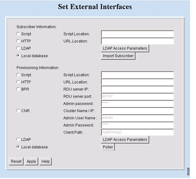
You can use the following methods to set up an external interface:
•
•
•
•
•
•
Note
Figure 10 shows the dialog box where you specify the method. The remainder of this section describes how to set up an external interface with each method, referring to Figure 10.
This section contains the following topics:
•
•
•
•
•
Figure 10 Set External Interfaces Dialog Box
Retrieving Data with a Script
You can implement an external data retrieval application by using a scripting language. To see a sample script that you can modify according to your needs, see "Shell Script for Retrieving Subscriber or Provisioning Information" section.
Note
Script Parameters for MAC Address Information
The script must support the ability to search for a cable modem's MAC address by entering the customer's phone number or IP address. The input parameters for the script are:
•
•
For example, the following script invokes a search for the modem's MAC address by using the phone number 408-123-4567:
/opt/tools/subscriber-query.sh GET_MAC PHONE 4081234567The next script invokes a search for the modem's MAC address by using the IP address 172.2.3.1:
/opt/tools/provision-query.sh GET_MAC IP 172.2.3.1
Note
The output of the script must be in the following format:
OUT_DATA=MAC followed by one or more MAC addresses (non-dotted format) separated by ^
The following examples show the output for one and two MAC addresses:
OUT_DATA=MAC^001c64ff23ef^
OUT_DATA=MAC^001c64ff23ef^013e45ed1245^
Script Parameters for Subscriber Information
If you use a script to query subscriber information, it needs to support the ability to search for subscriber data, such as name and account number, by entering the MAC address of the subscriber's cable modem. The input parameters for the script are:
script-name GET_SUBSCRIBER MAC non-dotted-modem-mac-address
For example, the following script invokes a search for subscriber data by using the MAC address 001c.ab23.45fe in a non-dotted format:
/opt/tools/subscriber-query.sh GET_ SUBSCRIBER MAC 001cab2345feThe output of the script must be in the following format, separated by ^:
OUT_DATA=SUBSCRIBER^Field1=value1^Field2=value2^Field3=value3^Field4=value4^Field5=value5^
The following example shows the output for a subscriber's data:
OUT_DATA=SUBSCRIBER^Account Number=123456^Name=Doe_John^Address=123 Tasman, San Jose, CA 93443^Phone=4081234567^Class of Service=N/A^FiberNode=FIBER_1^Customer Since=1999^Account Status=Paid
Note
Script Parameters for Provisioning Information
If you use a script to query provisioning information, it needs to support the ability to search for provisioning data, such as CMTS and cable modem IP addresses, by entering the MAC address of a cable modem. The input parameters for the script are:
script-name GET_PROVISION MAC non-dotted-modem-mac-address
For example, the following script invokes a search for provisioning data by using the MAC address 001c.ab23.45fe:
/opt/tools/subscriber-query.sh GET_PROVISION MAC 001cab2345feThe output of the script must be in the following format:
OUT_DATA=PROVISION^cmts-ip-address^cm-ip-address^
The following example shows the output for provisioning data:
OUT_DATA=PROVISION^127.23.45.1^127.23.127.5^
Error Handling for Script
If an error occurs within the script or the embedded application called by the script, the script should return the output in the following format:
OUT_DATA=ERROR^error-message^
The following example shows output for an error:
OUT_DATA=ERROR^Unable to query the subscriber database.^
In the graphical user interface (GUI), CBT displays the error message to the user in a message box.
Retrieving Data with a Script
Perform the following steps to retrieve subscriber or provisioning information by using a script:
Step 1
Step 2
•
•
For a complete description of each field in the External Interface dialog box, click Help.
Troubleshooting Script Problems
See the "Troubleshooting the Script" section.
Retrieving Data with an Application on an HTTP Server
You can implement an external data retrieval application by using an application running on an HTTP server. CBT sends the request to the HTTP server by using the POST method. To see a sample application file that you can modify according to your needs, see "Java Code for Retrieving Subscriber or Provisioning Information" section.
HTTP Parameters for MAC Address Information
The application running on an HTTP server must support the ability to search for a cable modem's MAC address by entering the customer's phone number or IP address. CBT sends the following parameters to the appropriate server:
•
•
•
For example, the following parameters search for the modem's MAC address by using the phone number 408-123-4567:
REQUEST=GET_MACSEARCH_TYPE=PHONEIN_PARAM=4081234567The response from the server must be in the following format:
OUT_DATA=MAC followed by one or more MAC addresses separated by ^
The following examples show the output for one and two MAC addresses:
OUT_DATA=MAC^001c64ff23ef^
OUT_DATA=MAC^001c64ff23ef^013e45ed1245^
Note
HTTP Parameters for Subscriber Information
If you use an application running on an HTTP server to query subscriber information, it needs to support the ability to search for subscriber data, such as name and account number, by entering the MAC address of the subscriber's cable modem. CBT sends the following parameters to the server:
•
•
•
For example, the following parameters search for subscriber data by using the MAC address 001cab2345fe:
REQUEST=GET_SUBSCRIBERSEARCH_TYPE=MACIN_PARAM=001cab2345feThe output of the script must be in the following format, separated by ^:
OUT_DATA=SUBSCRIBER^Field1=value1^Field2=value2^Field3=value3^Field4=value4^Field5=value5^
The following example shows the output for a subscriber's data:
OUT_DATA=SUBSCRIBER^Account Number=123456^Name=Doe_John^Address=123 Tasman, San Jose, CA 93443^Phone=4081234567^Class of Service=N/A^FiberNode=FIBER_1^Customer Since=1999^Account Status=Paid
Note
HTTP Parameters for Provisioning Information
If you use an application running on an HTTP server to query provisioning information, it needs to support the ability to search for provisioning data, such as CMTS and cable modem IP addresses, by entering the MAC address of the cable modem. CBT sends the following parameters to the server:
•
•
•
For example, the following parameters search for provisioning data by using the MAC address 001cab2345fe:
REQUEST=GET_PROVISIONSEARCH_TYPE=MACIN_PARAM=001cab2345feThe response from the server must be in the following format:
OUT_DATA=PROVISION^cmts-ip-address^cm-ip-address^
The following example shows the output for provisioning data:
OUT_DATA=PROVISION^127.23.45.1^127.23.127.5^
Error Handling for HTTP
If an error occurs within the application running on an HTTP server, the script should return the output in the following format:
OUT_DATA=ERROR^error-message^
The following example shows output for an error:
OUT_DATA=ERROR^Unable to query the subscriber database.^
In the GUI, CBT displays the error message to the user in a message box.
Retrieving Data with an HTTP Application
Perform the following steps to retrieve subscriber or provisioning information with an application on an HTTP server:
Step 1
Step 2
•
•
For a complete description of each field in the External Interface dialog box, click Help.
Troubleshooting HTTP Problems
See "Troubleshooting the Sample HTTP Application" section.
Retrieving Data with LDAP
You can use Lightweight Directory Access Protocol (LDAP) to retrieve external subscriber or provisioning information. LDAP is a nonproprietary, standards-based protocol. If you use the LDAP method, see your LDAP server administrator to obtain the information about the LDAP server that CBT requires.
CBT 3.3 supports LDAP Version 2.0, which was tested with Netscape LDAP Server Version 4.0 and iPlanet Version 5.1.
Perform the following steps to retrieve external subscriber or provisioning information by using LDAP:
Step 1
Step 2
•
•
Step 3
Retrieving Data with BPR
You can retrieve provisioning information only by using BPR, which stands for Cisco Broadband Provisioning Registrar. BPR automates provisioning and configuration tasks. CBT supports BPR 2.0. For product information, refer to:
http://www.cisco.com/en/US/products/sw/netmgtsw/ps529/index.html
Note
Perform the following steps to retrieve provisioning information by using BPR:
Step 1
Step 2
•
•
•
For information on each field, click Help.
Retrieving Data with CNR
You can retrieve provisioning information only by using CNR, which stands for Cisco Network Registrar. CNR is an application that provides scalable Domain Name System (DNS), Trivial File Transfer Protocol (TFTP), and Dynamic Host Configuration Protocol (DHCP) services. For product information, refer to:
http://www.cisco.com/en/US/products/sw/netmgtsw/ps1982/index.html
If you use CNR, the following caveats apply to the setup:
•
•
•
•
Note
Perform the following steps to retrieve provisioning information by using CNR:
Step 1
Step 2
•
•
•
•
For information on each field, click Help.
Retrieving Subscriber Data from the Local Database
CBT can retrieve subscriber data from its own local Sybase database after the data has been added in CBT. After installation, the local catabase is the default method for retrieving subscriber data.
Perform the following steps to retrieve subscriber information from the local database:
Step 1
Step 2
Step 3
Step 4
Figure 11 Import Subscriber Data Dialog Box
Retrieving Provisioning Data from the Local Database
CBT can retrieve provisioning data from its own local Sybase database after the data has been added to it. After installation, the local database is the default method for retrieving provisioning data. To store provisioning information in its local database, CBT polls CMTSs using SNMP. CBT provides two ways to do this:
•
•
Tip
About the Poller
When you install CBT, the default method for retrieving provisioning information is the local database. Because the Poller is part of the process for this method, it is on by default after installation. The default schedule for the Poller is to run at or about midnight and to repeat every 24 hours. You can change these settings according to your own needs.
To query Cisco CMTSs using the Poller, you specify two parameters:
•
•
The syntax to start the Poller on Linux or Solaris is:
/opt/CSCOcbt/bin/start_poller delta-start-time poll-interval
The following example shows a polling session that starts 8 hours after you schedule it and repeats every 24 hours:
/opt/CSCOcbt/bin/start_poller 8 24The following example shows how to stop the Java Poller application on Linux or Solaris:
/opt/CSCOcbt/bin/stop_poller
Note
At each polling interval, the Poller accesses the CBT routers list file and performs SNMP queries to each CMTS using its SNMP read-only community string. The CBT routers list file is in the following locations:
•
•
•
In addition to the on-demand polling that you schedule, CBT submits a polling request when it detects that a change has been made to the list of routers that CBT manages. For example, CBT submits a polling request when it detects that a new chassis has been added to a router.
Note
Perform the following steps to retrieve provisioning information from the local database:
Step 1
Step 2
Step 3
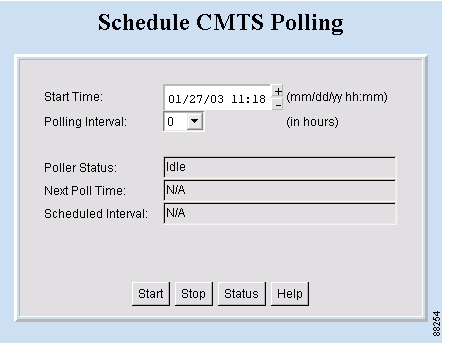
Scheduling the Poller
To schedule when and how often the Poller populates the local database with provisioning information that it gathers from CMTSs, you can use the GUI or type a command.
To use the GUI, from the Configuration menu, choose Poller. The Schedule CMTS Polling dialog box appears, as shown in Figure 12. In this dialog box, click Help for directions on how to schedule the Poller.
To use a command, type the following command and specify the parameters in hours, as explained in the previous section:
/opt/CSCOcbt/bin/start_poller delta-start-time poll-intervalFigure 12 Schedule CMTS Polling Dialog Box
Getting Summary Information and a Detailed Real-Time Status Report for a Modem
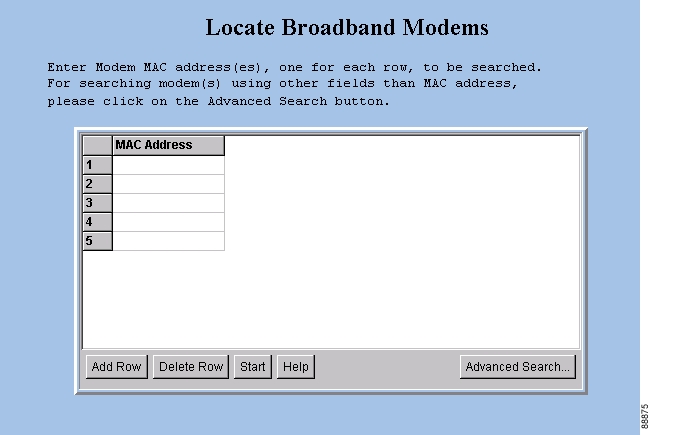
To get summary information on a cable modem, you can locate the modem by entering the MAC address. If you retrieve subscriber or provisioning data from the local database, you can also locate the modem by using any of the following advanced search criteria:
•
•
•
•
•
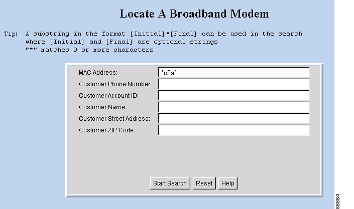
The CBT advanced search feature also allows you to use the asterisk (*) for wildcard searches. For example, if you enter 1234* for the account ID, you get a list of all cable modems for subscribers who have account numbers that begin with 1234.
Note
To get detailed information on a cable modem, you can get a real-time modem status report, as shown in Figure 13. The information for a cable modem comes from three sources:
•
•
•
Within the status report, the following colors are used in certain fields to indicate performance:
•
•
For more information on setting thresholds, see the "Modem Status Thresholds" section.
This section contains the following topics:
•
•
•
•
•
•
Figure 13 Real-Time Modem Status Report Data Display
Getting Summary Information on a Modem
DETAILED STEPS
Perform the following steps to get summary information on a modem:
Step 1
Step 2
•
•
For a complete description of each field in these dialog boxes, click Help.
Figure 14 Locate Broadband Modems Dialog Box
Figure 15 Locate A Broadband Modem Dialog Box
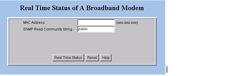
Getting a Detailed Real-Time Status Report for a Modem
Perform the following steps to get a detailed status report for a cable modem:
Step 1
Step 2
For a complete description of each field in the dialog box and the Real-Time Modem Status Report, click Help.
Figure 16 Real Time Status of ABroadband Modem Dialog Box
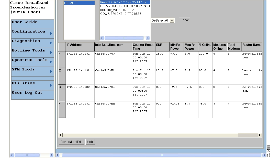
Reviewing the CMTS Dashboard
To get summary information on a Cisco CMTS, review the CMTS Dashboard dialog box. Figure 17 shows the CMTS Dashboard.
Figure 17 CMTS Dashboard Dialog Box
For the CMTS that you select, the CMTS Dashboard provides the following information:
•
•
•
•
•
•
•
•
•
•
•
For printing or collaborative troubleshooting, you can generate an HTML version of the information.
Perform the following steps to access the CMTS Dashboard:
Step 1
For a complete description of each field in the CMTS Dashboard dialog box, click Help.
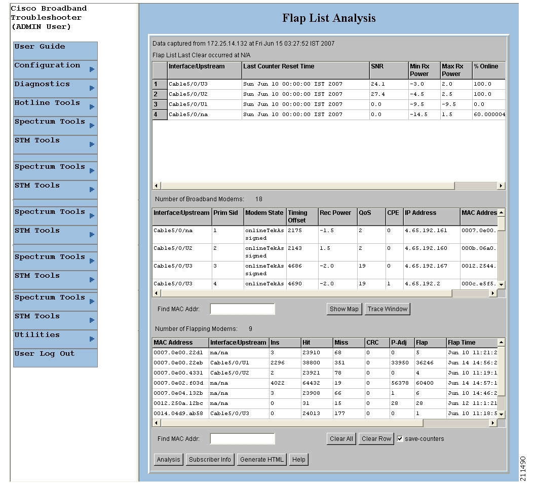
Showing and Configuring the Flap List Analysis
To analyze the results of data captured from one or more Cisco CMTSs, review the Flap List Analysis Details display. The analysis shows the number of modems with the following problems:
•
•
•
•
Note
Figure 18 shows the Flap List Analysis information display, which you can sort according to your needs by clicking a column heading. For example, to sort the provisioning problems by MAC address, click the MAC Address column heading.
Figure 18 Flap List Analysis Details Display
From the Flap List Analysis Details information display, you can see a lower level of detail that contains the following information:
•
•
•
The detailed level of the Flap List Analysis detail display is shown in Figure 19.
Figure 19 Flap List Analysis Details Display
Showing the Flap List Analysis
Perform the following steps to show a flap list for one or more CMTSs:
Step 1
Step 2
Step 3
Note
For a complete description of each field in the Flap List Analysis dialog boxes, click Help.
Scheduling the Flap List Analysis
To schedule a time to capture raw data from one or more Cisco CMTSs, use the Scheduler Configuration dialog box, which is shown in Figure 20.
Figure 20 Scheduler Configuration Dialog Box
Perform the following steps to schedule a time to capture raw data from one or more Cisco CMTSs:
Step 1
Step 2
Step 3
For a complete description of each field in the Scheduler Configuration dialog box, click Help.
Setting Parameters for the Flap List
The administrator can set parameters for the flap list in the Flap List Configuration dialog box shown in Figure 21.
Note
Figure 21 Flap List Configuration Dialog Box
For a Cisco CMTS, the administrator can specify the following criteria for a flap list:
•
•
•
•
•
Perform the following steps to set parameters for the flap list:
Step 1
Step 2
For a complete description of each field in the Flap List Configuration dialog box, click Help.
Purging the Flap List
When you want to delete a saved flap list file, use the Purge Flap List Data File dialog box, which is shown in Figure 22. Before you purge a flap list file, you can generate an HTML version of it.
Figure 22 Purge Flap List Data File Dialog Box
Perform these steps to purge a flap list file:
Step 1
Step 2
For a complete description of each field in the Purge Flap List Data File dialog box, click Help.
Using the Spectrum Management Tools
CBT 3.3 interfaces with the Cisco CMTS to provide return path spectrum analysis, which is provided in the following tasks:
•
•
•
•
•
–
–
Each task is covered in the following sections:
•
•
•
•
•
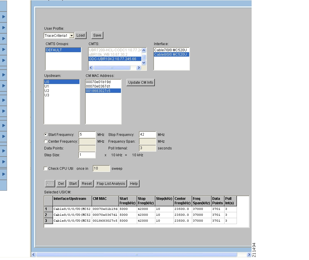
Using the Trace Window
To monitor power and noise levels for a selected modem or upstream port, use the Trace Window. As shown in Figure 23, the Trace Window shows the output that you would see in a spectrum analyzer. This output displays in the plot line of the Trace Window.
Figure 23 Trace Window Display
In the Trace Window, you can:
•
–
–
•
–
–
•
–
–
–
•
–
–
•
–
–
–
–
•
–
–
•
•
•
Working with the Trace Window
Table 1 shows several ways to work with data in the Trace Window.
Table 1
Keyboard Actions for Working with the Trace Window
Starting the Trace Window
Perform the following steps to use the Trace Window to monitor power and noise levels for a selected modem or upstream port:
Step 1
Step 2
Note
Tip
Step 3
Step 4
•
•
For a complete description of each field in these dialog boxes, click Help.
Figure 24 Trace Window Criteria Dialog Box
Viewing Trace Windows
Some browsers give the user the ability to stop windows from being launched by the browser. CBT 3.3 normally launches a new window to display the trace pop-up spectrum data charts. If the data chart window does not appear and the browser is configured to stop new windows from launching, you can configure CBT 3.3 to display data charts within the browser window.
Perform the following steps to configure CBT 3.3 to display data charts within the browser window:
Step 1
Step 2
Sorting Support in the CBT 3.3 Graphical User Interface
CBT 3.3 introduces sorting support for the List fields in the following GUI pages:
•
•
•
•
•
Perform the following steps to change the order of sorting:
Step 1
•
•
•
•
•
Step 2
Using Auto-Select in the Trace Window
CBT 3.3 does not select any given field in the Trace Window by default. To retrieve and display information for any given field in the Trace Window display, select the desired field.
Using the Spectrogram
To monitor power and noise levels, as you do in the Trace Window, while viewing the added dimension of time, use the Spectrogram. As shown in Figure 25, the Spectrogram shows the output that you would see in a spectrum analyzer.
Figure 25 Spectrogram
In the Spectrogram, you see the following variables in one easy, 3-D view:
•
•
•
When you move your cursor over the Spectrogram, the status bar at the bottom of the window displays the time, frequency, and power level for the current location. In the Spectrogram, you can click Pause or Print at anytime.
Starting the Spectrogram
Perform the following steps to use the Spectrogram to monitor power and noise levels for a selected modem or upstream port over time:
Step 1
Step 2
Note
Step 3
For a complete description of each field in these dialog boxes, click Help.
Step 4
Figure 26 Spectrogram Criteria Dialog Box
Figure 27 Spectrogram Criteria Confirmation Dialog Box
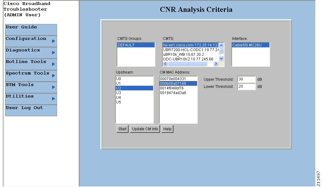
Analyzing the Carrier-to-Noise Ratio
To show the carrier-to-noise ratio for selected cable modems or upstream ports, use the CNR Analysis task. As shown in Figure 28, this information displays in the CNR Analysis dialog box, which lets you:
•
–
–
–
–
•
Figure 28 CNR Analysis Dialog Box
You can set the following SPECTRUM.INI file parameters:
•
•
In Figure 28, the CNRs for the selected modems fall into three categories:
•
•
•
For more information on the SPECTRUM.INI file, see the "Parameters in the SPECTRUM.INI File" section.
Getting the CNR Analysis
Perform the following steps to show the carrier-to-noise ratio for selected cable modems or upstream ports:
Step 1
Step 2
Note
Tip
Step 3
For a complete description of each field in these dialog boxes, click Help.
Figure 29 CNR Analysis Criteria Dialog Box
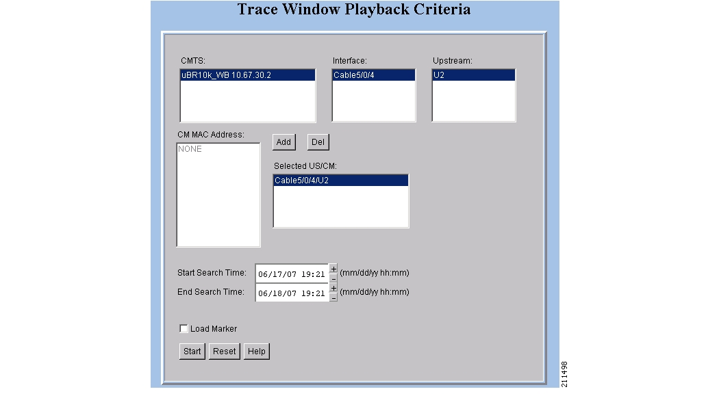
Playing Back Data
You can play back a saved Trace Window or CNR Analysis. This allows you to capture and preserve troubleshooting information and use it later.
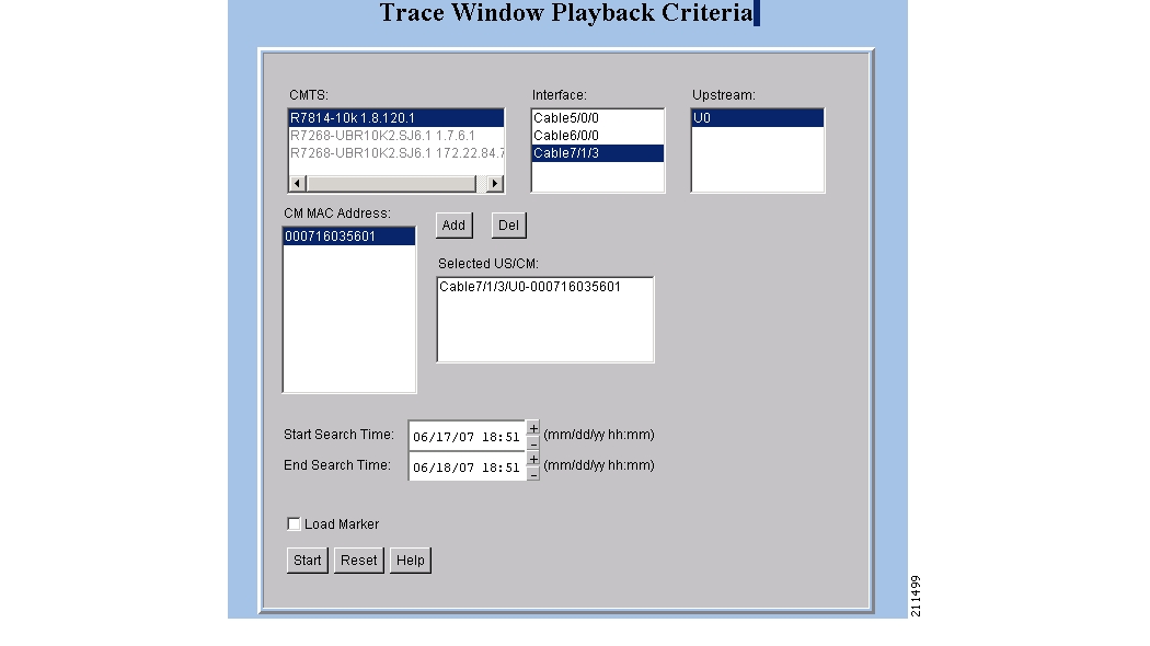
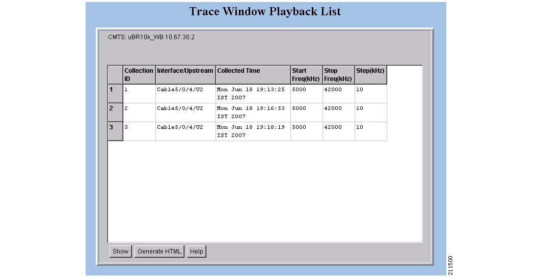
Playing Back a Trace Window
Perform the following steps to play back a Trace Window:
Step 1
Step 2
Step 3
Note
For a complete description of each field in these dialog boxes, click Help.
Figure 30 Trace Window Playback Criteria Dialog Box
Figure 31 Trace Window Playback Criteria Dialog Box, Alternate View
Figure 32 Trace Window Playback List Dialog Box
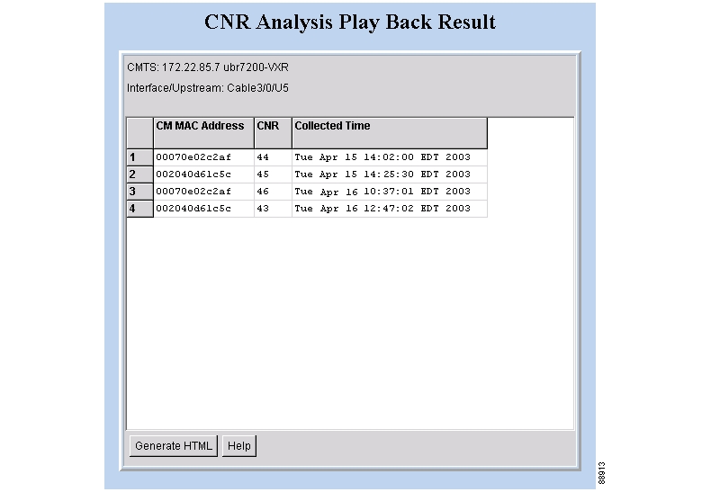
Playing Back a CNR Analysis
Perform the following steps to play back a CNR Analysis:
Step 1
Step 2
Note
For a complete description of each field in these dialog boxes, click Help.
Figure 33 CNR Analysis Playback Criteria Dialog Box
Figure 34 CNR Analysis Playback Result Dialog Box
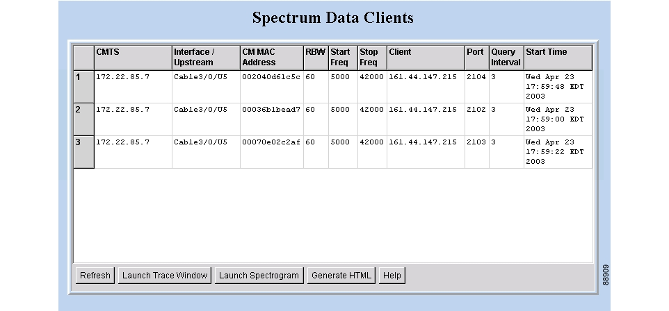
Working with Spectrum Management Clients
To see a list of clients that are currently using CBT spectrum management tools, use the Clients task option of the Trace Window or Spectrogram dialog boxes. The Clients task feature is an effective tool that optimizes the CBT diagnostic capabilities by listing all in-process spectrum analyses in one place. By using the Clients task tool, technicians can troubleshoot collaboratively because multiple technicians can simultaneously perform the following:
•
•
When you choose the Clients task, the Spectrum Data Clients dialog box appears. See Figure 35.
Figure 35 Spectrum Data Clients Dialog Box
Using the Clients Task
In the Spectrum Data Clients dialog box, each row represents a spectrum analysis in process on a client machine. For each spectrum analysis in the list, you can:
•
–
–
–
–
–
–
–
–
–
–
•
As you work in the Spectrum Data Clients dialog box, you can click Refresh to update the information or Generate HTML to capture the information in a format that can be distributed easily outside of Cisco Broadband Troubleshooter. For example, you could send it as an attachment in a trouble-ticket system or email application.
Perform the following steps to see a list of spectrum analyses in process on client machines:
Step 1
Tip
For a complete description of each field in the Spectrum Data Clients dialog box, click Help.
Enabling Instantaneous CPU Assessment for Spectrum Polling
CBT 3.3 enables the option of preventing excessive CPU consumption, in circumstances in which the Trace Window, Spectrogram functions, or Scheduled Polling features might otherwise exceed CPU bandwidth.
CBT has provisions to instantaneously check the CPU utilization and prevents the spectrum operation if the CPU utilization exceeds the CPU thresholds (value of SpecDataMaxCPU parameter).
Perform these steps to enable or disable CPU assessment in the Trace Window Criteria dialog box, the Spectrogram Criteria dialog box, or the Spectrum Data Scheduler dialog box before launching the spectrum event.
Step 1
Step 2
Step 3
•
•
•
Step 4
Figure 36
Check CPU Util Dialog Box
Step 5
This setting means that the CPU utilization is checked and compared with the SpecDataMaxCPU parameter. Upon positive results, the spectrum operation gets started. The spectrum data is collected continuously with the specified poll interval.
One sweep corresponds to a single polling of spectrum data. After 10 such polling events, CBT again checks the CPU Utilization and compares it with the SpecDataMaxCPU parameter. If the results are positive, the spectrum operation continues; otherwise, the continuous query is stopped. If the number of sweeps is 1, then the CPU utilization is checked before every polling of spectrum data.
Step 6
Administrative Tasks for CBT 3.3
This section describes administrative configuration tasks that improve additional functions of CBT 3.3:
•
•
Mapping Hostnames from Applet to Servlet
CBT 3.3 introduces support for hostname-based communications between applet and aervlet on the network, in addition to sustaining IP-based communications, as with the prior CBT 3.2.
In CBT 3.2 all the communication between the applet and the servlet was based only on the IP address of the server. Every request and response between the applet and servlet had the IP address in the URL. CBT 3.3 removes this limitation, to support both hostnames and IP addresses.
This procedure changes the UseHostName parameter of the GUNSLINGER.INI file. By default, this value is NO in CBT 3.3. Changing this value to YES enables hostname-based communication between applet and servlet, and removes IP addresses from corresponding displays and processing.
Some Web proxy functions only allow hostname-based IP communication, and otherwise drop communications with IP addresses in the URL. This feature is helpful in such cases.
This procedure requires that applet and servlet hostnames be established and otherwise functional on the network prior to mapping hostnames in CBT 3.3. Both the client and server should be able to resolve the hostname of the CBT server machine.
Perform these steps to map hostnames from applet to servlet.
Step 1
•
•
Step 2
•
•
Step 3
Step 4
Configuring Administrative Parameters for Spectrum Analysis
CBT releases prior to CBT 3.3 support options for spectrum operation parameters, and CBT 3.3 continues support for these parameters. CBT 3.3 introduces support for adminstrators to configure upper and lower limits for multiple fields in the Spectrum Operations windows. CBT 3.3 introduces additional configurable parameters in the SPECTRUM.INI file.
Perform the following steps to define administrative upper and lower limits in Spectrum Operations windows.
Step 1
•
•
Step 2
•
•
•
•
•
•
•
•
•
•
•
•
•
•
•
•
You can configure the upper and lower limit for the start, stop frequency, poll interval, step size and data points. While entering such data spectrum parameters, CBT 3.3 sustains native-level validation, and additionally, CBT 3.3 validates entries with respect to the newly configured limits in the SPECTRUM.INI file. The following list describes various fields and supported ranges for validation in a Spectrum Event:
•
•
•
–
–
Validation is performed on Center Frequency and Frequency Span in the following way:
–
–
–
As a result, these values should be in the range 5 to 65. In this way both the fields are validated.
•
–
–
•
•
•
•
•
•
•
–
•
•
Note
Step 3
Example
If the value of the SpecEventPollIntervalMinValue parameter is set to 1, then only values above 1 are accepted in the Poll Interval dialog box. This example removes the bandwidth-consuming zero-second polling.
Troubleshooting Tips for CBT 3.3
This section contains the following procedures for verifying and troubleshooting CBT 3.3:
•
•
•
•
•
•
Troubleshooting Continuous Sweep Spectrum Operation in CBT 3.3
A non-standard behavior has been observed in which the Continuous Spectrum Operation of CBT 3.3 fails, even in circumstances in which the Single Sweep Spectrum Operation remains functioning. One example would be the proper Trace Window single sweep operation, but with failed Continuous Sweep behavior in the Trace Window.
CBT 3.3 requires that the following processes and tasks be used for Continuous Sweep Operation.
Step 1
•
•
•
•
•
•
Step 2
•
•
•
•
Changing Server Ports in XML Script
Cisco IOS Release 12.3(9a)BC changes the Tomcat server port in server XML script. The script is set to port 8105. This prevents possible port conflict when multiple Tomcat Web servers are running on the same workstation.
If required, perform the following steps to change the Tomcat server port in XML script to port 8105 and check for additional port conflicts:
Step 1
/opt/CSCOcbt/httpServer/conf
Step 2
•
•
•
•
Saving System Message Logs for Troubleshooting
When troubleshooting CBT 3.3, we recommend that message logs be saved and filtered using the following steps.
Step 1
This is a fixed-size log file that continuously removes the oldest entry as it is updated. This log file is not viewable using an editor (such as vi).
Step 2
Step 3
For Solaris and Linux, the log file is located at /opt/CSCOcbt/httpServer/logs/catalina.out. This file is viewable with viewing utilities such as vi, Cat, Tail, or others.
Note
Verifying Installation Status on the CBT 3.3 Server
Perform the following steps to verify the status of the installed CBT 3.3 server.
Step 1
•
•
Step 2
•
ps -ef|grep dberoot 26449 1 0 Aug 18 ? 0:24 dbeng8 -x tcpip{ServerPort=2640} -q -ud -s local0 -m -c 16M -n cbtdbengine /opt•
There is a Sybase icon shown as a running process.
Step 3
•
ps -ef|grep javaroot 26478 1 0 Aug 18 ? 0:39 /opt/CSCOcbt/jre/bin/java -DCBTpoller -cp /opt/CSCOcbt/httpServer/webapps/ROOT/root 26489 1 0 Aug 18 ? 148:55 /opt/CSCOcbt/jre/bin/java -Djava.endorsed.dirs=/var/CSCOcbt/httpServer/common/e
Note
•
Use the command console for Tomcat and the CBT poller to view log messages.
Verifying the CBT 3.3 License
Perform the following steps to verify the CBT 3.3 installation license.
Step 1
1.
/opt/CSCOcbt/httpServer/webapps/ROOT/WEB-INF/classes/lic/License
2.
3.
/opt/CSCOcbt/httpServer/logs/
Step 2
1.
INSTALLATION_DIR\httpServer\webapps\ROOT\WEB-INF\classes\lic\License
2.
3.
Troubleshooting the Poller
This section provides directions to troubleshoot error messages for the following CBT components:
•
•
•
Troubleshooting Poller Problems
You can use the Poller, a separate Java application, to store provisioning information in the CBT local Sybase database. This database Poller queries the CMTSs by using SNMP. If the Debug parameter in POLLER.INI is set to true, the Poller sends information to the Poller.log file in the following location:
•
•
Note
This section:
•
•
•
Error Message: No Router
Problem
The following output from Poller.log indicates that no router was found:
Thu Jun 27 15:47:35 EDT 2002: INFO: Start polling...Thu Jun 27 15:47:37 EDT 2002: INFO: No router found in routers list file: /opt/CSCOcbt/jakarta-tomcat-4.0.3/webapps/ROOT/WEB-INF/classes/config/myroutersThu Jun 27 15:47:37 EDT 2002: INFO: Finished polling... elapsed time: 2371 millisecondsThu Jun 27 15:47:37 EDT 2002: INFO: Poller exited.Cause
No router was found in the routers list file, myrouters, because of one of the following conditions:
•
•
Resolution
To add routers in CBT, see the "Adding Router Information" section.
Error Message: Database Login Failed
Problem
The following output from Poller.log indicates that the login to the database failed:
Wed Jun 26 11:14:12 PDT 2002: INFO: Start polling...Wed Jun 26 11:14:13 PDT 2002: FATAL: SQL Exception in setupDB makeDBConnection: 1JZ00L: Login failed. Examine the SQLWarnings chained to this exception for the reason(s).Software aborted.Cause
The database login failure occurs because the database ran out of connections; that is, it tried to use more connections than it can support.
Resolution
If the database ran out of connections, restart CBT to clear all existing database connections and start the database.
Error Message: SNMP Timeout
Problem
The following output from Poller.log indicates that an SNMP timeout has occurred:
Thu Jun 20 13:45:08 EDT 2002: INFO: Start polling...Thu Jun 20 13:45:18 EDT 2002: ERROR: Thread16 got SNMP exception on Router: 24.216.122.254. Exception: Snmp Timeout... Router 24.216.122.254 is unreachableCause
The SNMP timeout occurs when the network connection to the router, or the router itself, is so busy that it cannot satisfy the request within the specified time.
Resolution
If the SNMP timeout occurs too frequently, change the SNMP settings in the POLLER.INI file:
Step 1
•
•
Step 2
•
•
Step 3
Tip
Uninstalling Cisco Broadband Troubleshooter
This section provides instructions to uninstall Cisco Broadband Troubleshooter on each supported platform.
Uninstalling CBT on Solaris
Step 1
Step 2
Step 3
cd/cdrom/cdrom0/solaris/cbtStep 4
./uninstallOtherwise, refer to the following general uninstall procedure, as cited in the "Uninstalling Prior CBT Releases" section.
If there is a previous CBT installation (CBT 2.x, CBT 3.0 or CBT 3.2), uninstall it using the following steps.
•
Uninstalling CBT on Windows
Step 1
Start > Settings > Control Panel > Add/Remove Programs
Step 2
Step 3
Otherwise, refer to the following general uninstall procedure, as cited in the "Uninstalling Prior CBT Releases" section.
If there is a previous CBT installation (CBT 2.x, CBT 3.0 or CBT 3.2), uninstall it using the following steps.
•
–
–
Uninstalling CBT on Linux
Step 1
Step 2
Step 3
/bin/mount /mnt/cdromStep 4
cd /mnt/cdrom/linuxStep 5
./uninstallOtherwise, refer to the following general uninstall procedure, as cited in the "Uninstalling Prior CBT Releases" section.
If there is a previous CBT installation (CBT 2.x, CBT 3.0 or CBT 3.2), uninstall it using the following steps.
•
Sample Code for Application Program Interfaces
This section contains the README files for the following application program interfaces (APIs):
•
•
The sections that describe scripts and code provide the following information:
•
•
•
•
•
•
•
This section contains the following topics:
•
•
Shell Script for Retrieving Subscriber or Provisioning Information
You can use a sample script written for various databases to retrieve subscriber or provisioning information from an external source. These scripts, that you can modify according to your needs, are in the README file in the following locations:
•
–
–
•
–
–
This section provides a printed copy of that README file, formatted for this user guide.
Purpose of Shell Script
This section describes how to use scripts written against a Sybase database. The sybase directory contains sample scripts that you can modify to meet your needs. These scripts demonstrate how to:
•
•
•
Sample Script Requirements
The sample scripts have the following criteria for use:
•
•
After trying the sample scripts, you can tailor them for your database or any other external data source.
Script and File Descriptions
The following list of sample scripts describes the purpose of each script or file:
•
•
•
•
•
•
Modifying the Script
Perform the following steps to modify a script:
Step 1
Step 2
Step 3
Step 4
Step 5
Step 6
Step 7
Step 8
Troubleshooting the Script
•
./get_provision GET_PROVISION MAC 000216d5a0cf
OUT_DATA=PROVISION^172.22.85.10^172.22.127.26^
./get_provision GET_MAC IP 172.22.127.26
OUT_DATA=MAC^000216d5a0cf^
./get_subscriber GET_SUBSCRIBER MAC 000216d5a0cf
OUT_DATA=SUBSCRIBER^AccId=ID000006^Name=Name000006^Phone=6172300006^Address=175 West Tasman^ClassOfService=Policy000006^FiberNode=User A000006^
./get_subscriber GET_MAC PHONE 5106663152
OUT_DATA=MAC^000164ffeb95^000164ffc3c7^
./get_subscriber GET_ADDRESS MAC 000164ffc3c7^000164ffeb95^
OUT_DATA=ADDRESS^000164ffc3c7=170 West Tasman Drive,95134^000164ffeb95=170 West Tasman Drive,95134^
•
•
•
–
–
•
–
@echo off–
For example:
echo OUT_DATA=PROVISION^^172.22.85.10^^172.22.127.26^^
Sample Script Code
The following sample code is extracted from the get_subscriber script:
#!/bin/kshargc=$#set -A argv $*integer i=0while let "i < $argc"; docase ${argv[$i]} in"GET_MAC") function=${argv[$i]};;esaclet "i = i + 1"done#retrieving MAC based on Customer phone numberif [ "$function" = "GET_MAC" ] ; thenstr="SELECT MACAddress FROM SUBSCRIBERINFO where CusPhone='$in_param';";echo $str >> "$tmpDir/script.$filenameExt"str="OUTPUT TO $tmpDir/test.$filenameExt FORMAT ASCII;"echo $str >> "$tmpDir/script.$filenameExt"tmpi=`dbisqlc -q -c $dbAccess read $tmpDir/script.$filenameExt`rm $tmpDir/script.$filenameExtMAC=`$commLib/cat $tmpDir/test.$filenameExt | $commLib/sed s/\'//g`echo $MAC > $tmpDir/test.$filenameExtMAC=`$commLib/cat $tmpDir/test.$filenameExt | $commLib/sed 's/ /^/g'`tmp="OUT_DATA=MAC^$MAC^";if [ $tmp = "OUT_DATA=MAC^^" ] ; thenecho "OUT_DATA=ERROR^No data found for $in_param^";exit;fiecho $tmprm $tmpDir/test.$filenameExtexit;fiJava Code for Retrieving Subscriber or Provisioning Information
You can use an application that is running on an HTTP server to retrieve subscriber or provisioning information from an external source.
A sample application that you can modify according to your needs is in the README file in the following locations:
•
–
–
•
–
–
This section provides a printed copy of that README file, formatted for this user guide.
Purpose of Java Code
This sample script file describes how to use Data Manager, a sample HTTP application. The HTTP directory contains this sample application that you can modify to meet your needs. Data Manager demonstrates how to:
•
•
•
Sample HTTP Application Requirements
The sample HTTP application:
•
•
Module and File Descriptions
This section lists the modules and files used in Data Manager, the sample HTTP application. For a description, refer to a specific module or file. To modify Data Manager to suit your needs, refer to the next section, "Modifiable Components in the Data Manager Application."
•
–
–
–
–
–
–
–
–
–
–
–
–
–
–
•
–
–
–
–
–
–
•
–
–
–
Modifiable Components in the Sample HTTP Application
•
•
–
–
–
–
–
–
If create_tbls.sql is changed, the code for these functions must be changed accordingly.
•
Db-Vital.properties—Contains attributes of the provisioning database.If the provisioning and subscriber data tables reside in the same database, these two files must have identical information. In Data Manager, the provisioning and subscriber data is in two separate databases.
For both files, the following settings must be changed accordingly:
–
–
–
–
•
•
The current variable settings in start_dm are:
debug_flag=1(Send debug messages to a log file.)port=8012(Change to the port of your choice.)logDir= /opt/CSCOcbt/jakarta-tomcat-4.0.3/logs(Specify the location where the log file should be created and changes should be written.)•
The following variable settings are in stop_dm:
ip=171.71.50.52(IP address where the HTTP application is running.)port=8012(Port in which the HTTP application is running. This should be the same port specified in the start_dm script.)For these three scripts (Makefile, start_dm, and stop_dm), the following properties must be updated according to the system environment:
–
–
–
Building and Running the Sample HTTP Application
1.
From the command line, type:
./make
./install
2.
From the command line, type:
/opt/CSCOcbt/bin/start_dm
3.
From the command line, type:
/opt/CSCOcbt/bin/stop_dm
4.
a.
b.
c.
http://your_machine_name:port_num/DataManager5.
http://your_machine_name:port_num/DataManager
Note
Troubleshooting the Sample HTTP Application
•
Make sure there is connectivity between the machine and the Oracle database. A quick way to test this is to invoke the Oracle SQL*Plus application. For example, assume that the following settings are in Db-Vital.properties:
–
–
–
From the command line, type:
sqlplus user1/mypasswd@CBT
If there is no response or an error occurs, check the tnsnames.ora setting.
•
Make sure that JAVA_HOME in the Makefile points to the correct JAVA compiler.
•
The sample HTTP application was written to use the Oracle OCI protocol for communicating with the database. Oracle OCI requires machine-dependent libraries, so make sure that the path to the libraries is set correctly in Makefile.
•
This error occurs when port_num is changed in start_dm and stop_dm. To correct it, restart the program /opt/CSCOcbt/bin/start_dm program.
•
It is possible that some of the Oracle environment did not get set up correctly. To check this, review oracle.csh, update it as required, and source it. Then, run start_dm again.
Sample Java Code
1.
HttpRequest = new HttpRequest()2.
StringBuffer sb = new StringBuffer();InputStream is = sock.getInputStream();DataInputStream fromBrowser = new DataInputStream(is);while (true) {msg = fromBrowser.readLine();if (msg.equals("")) break;sb.append(msg + nl); // put back the '\n\r' for newline}3.
DataInputStream fromBrowser = sock.getInputStream();StringBuffer sb = new StringBuffer();for (int x=0; x < len; x++) {// return int range 0-255, -1: end of streami = fromBrowser.read();if (i == -1) break;// however, char is 16 bits for unicode 2 bytes// now use 2 bytes to hold just one byte data.sb.append((char)i);//System.out.println (sb);}4.
//parse and save message into HashtableString req_command = decodeString(command);//System.out.println ("req_command=" + req_command);// Parse the data from the servletStringTokenizer rdata = new StringTokenizer(req_command, "&");if (rdata == null) return;//System.out.println ("data=" + data + ", rdata=" + rdata);while (rdata.hasMoreTokens()) {String cmd = rdata.nextToken();int index = cmd.indexOf("=");if (index == -1) return;String key = cmd.substring(0, index);String val = cmd.substring(index+1);hParams.put(key, val);}5.
//if POST message then process the message:if (req.getReqType().equals ("POST")) {req.fetchBody(sock_);hParams = req.getParams();resp = new PostResponse(req);String status = null;status = dm_.processCommand(req);...}//examine the request type and process the message accordingly:Hashtable hParams = req.getParams();String task = (String)hParams.get("REQUEST");int status = 1;if (task.equals(GET_PROV_INFO)) {String sStr = "";String sType = (String)hParams.get("SEARCH_TYPE");if (sType.equals("MAC")){String sTmp = (String)hParams.get("IN_PARAM");String sMac = sTmp.toLowerCase();Logger.debug("In Mac is " + sMac);sStr = DbQuery.getProvInfo(sMac);Logger.debug("Prov Info is " + sStr);}.....}// retrieve information from the database (DbQuery.java):public static String getProvInfo(String Mac) {String query = "";String subscriberId = "";String modemIp = "";String cmtsIp = "";Statement stmt = null;try {long start = (new java.util.Date()).getTime();start = (new java.util.Date()).getTime();stmt = vital_db_conn.createStatement();query = "select subscriberid, ipaddress,giaddr from device where deviceid = '" + Mac + "'";Logger.debug(query);boolean bFound = false;ResultSet rs = stmt.executeQuery(query);while (rs.next()) {bFound = true;subscriberId = rs.getString(1);modemIp = rs.getString(2);cmtsIp = rs.getString(3);rs.clearWarnings();}rs.close();rs = null;stmt.close();stmt = null;long end = (new java.util.Date()).getTime();Logger.debug("total msec to execute getProvInfo: " + (end - start));if (!bFound)return ("OUT_DATA=ERROR^" + Mac + " does not exist in the Provisioning Database.^");String sStr = "OUT_DATA=PROVISION^" + cmtsIp + "^" + modemIp + "^";return (sStr);}catch (SQLException se) {String sError = "OUT_DATA=ERROR^" + se.getMessage() + "^";if (stmt != null){try {stmt.close();}catch (Exception e){}stmt = null;}return sError;}}6.
//send header to CBTOutputStream os = null;try {os = sock.getOutputStream();}catch (IOException e) {Logger.error("DataManager.HttpResponse:sendHeader: error: " + e);e.printStackTrace(DataManager.getLogPW());e.printStackTrace();}StringBuffer sb = new StringBuffer();sb.append ("HTTP/1.0 200 OK" + nl);sb.append ("Content-type: text/html" + nl);byte[] b = (sb.toString()).getBytes();try {os.write(b);os.flush();}catch (IOException e) {Logger.error ("DataManager.HttpResponse:sendHeader: error write: " + e);e.printStackTrace(DataManager.getLogPW());e.printStackTrace();}Send result data off to CBTos.write(result_data);os.flush();
![]()
![]()
![]()
![]()
![]()
![]()
![]()
![]()
Posted: Thu Aug 16 17:56:43 PDT 2007
All contents are Copyright © 1992--2007 Cisco Systems, Inc. All rights reserved.
Important Notices and Privacy Statement.