- Preface
- 1. About the MPLS/VPN BGP LEG
- MPLS/VPN Overview
- MPLS/VPN BGP LEG Overview
- Terms and Concepts
- BGP (Border Gateway Protocol)
- CE (Customer Edge)
- LEG (Login Event Generator)
- MPLS (Multi Protocol Label Switching)
- PE (Provider Edge)
- RD (Route Distinguisher)
- RR (Route Reflector)
- RT (Route Target)
- Subscriber Domain
- Subscriber ID
- Subscriber Mappings
- VPN (Virtual Private Networking)
- VRF (Virtual Routing and Forwarding)
- 2. Installing the MPLS/VPN BGP LEG
- 3. Configuring the MPLS/VPN BGP LEG
- 4. Managing MPLS/VPN Subscribers
- 5. MPLS/VPN BGP LEG Command-Line Utility (CLU)
This guide describes the concept of a Multi Protocol Label Switching/Virtual Private Network (MPLS/VPN) architecture using the Login Event Generator (LEG) based on the Border Gateway Protocol (BGP), and explains how to install and configure it on the SCMS Subscriber Manager (SM) platform.
Note
This guide assumes a basic familiarity with telecommunications equipment and installation procedures, Cisco SCMS subscriber management, subscriber integration concepts, and the MPLS/VPN architecture.
For complete information regarding Cisco's subscriber integration concept, see the Cisco Service Control Management Suite Subscriber Manager (SCMS SM) User Guide.
|
Cisco Service Center Release |
Part Number |
Publication Date |
|---|---|---|
|
Release 3.0.5 |
OL-8233-04 |
November, 2006 |
Description of Changes
Updated documentation for Release 3.0.5. No major changes or new features were added to this release.
|
Cisco Service Center Release |
Part Number |
Publication Date |
|---|---|---|
|
Release 3.0.3 |
OL-8233-03 |
September, 2006 |
Description of Changes
MPLS/VPN BGP LEG can be installed only on Red Hat Linux platforms.
|
Cisco Service Center Release |
Part Number |
Publication Date |
|---|---|---|
|
Release 3.0.3 |
OL-8233-02 |
May, 2006 |
Description of Changes
Added new section describing managing MPLS/VPN subscribers. See Managing MPLS/VPN Subscribers.
Added new section describing the VPN identifier. See VPN Identifier (RD or RT).
Various other small changes to text.
|
Release 3.0 |
OL-8233-01 |
December, 2005 |
This document is intended for system administrators and system integrators who are familiar with the MPLS/VPN BGP LEG concepts and with Cisco Service Control Subscriber Management and Subscriber Integration concepts.
This guide covers the following topics:
|
Chapter |
Title |
Description |
|---|---|---|
|
Chapter 1 |
Describes the MPLS/VPN BGP LEG software module, and terms and concepts | |
|
Chapter 2 |
Describes the installation process for installing the SM MPLS/VPN BGP LEG | |
|
Chapter 3 |
Provides the configuration instructions to configure the MPLS/VPN BGP LEG | |
|
Chapter 4 |
Describes the management of MPLS/VPN subscribers | |
|
Chapter 5 |
Describes the Command-Line Utility to control the operation of the SM MPLS/VPN BGP LEG and to retrieve information and statistics about the LEG |
This Reference Guide should be used in conjunction with the following Cisco documentation:
Cisco SCMS Subscriber Manager User Guide
Cisco Service Control Application for Broadband User Guide
This document uses the following conventions:
|
Convention |
Description |
|---|---|
|
boldface font |
Commands and keywords are in boldface. |
|
italic font |
Arguments for which you supply values are in italics. |
|
[ ] |
Elements in square brackets are optional. |
|
{x | y | z} |
Alternative keywords are grouped in braces and separated by vertical bars. |
|
[x | y | z] |
Optional alternative keywords are grouped in brackets and separated by vertical bars. |
|
string |
A nonquoted set of characters. Do not use quotation marks around the string, or the string will include the quotation marks. |
|
|
Terminal sessions and information that the system displays are in |
|
|
Information you must enter is in |
|
|
Arguments for which you supply values are in |
|
® |
This pointer highlights an important line of text in an example. |
|
< > |
Nonprinting characters, such as passwords, are in angle brackets. |
|
[ ] |
Default responses to system prompts are in square brackets. |
|
!, # |
An exclamation point (!) or a pound sign (#) at the beginning of a line of code indicates a comment line. |
Note
Means reader take note. Notes contain helpful suggestions or references to materials not covered in this manual.
Caution
Means reader be careful. In this situation, you might do something that could result in loss of data.
The following sections provide sources for obtaining documentation from Cisco Systems.
You can access the most current Cisco documentation on the World Wide Web at the following sites:
Cisco documentation and additional literature are available in a CD-ROM package that ships with your product. The Documentation CD-ROM is updated monthly and may be more current than printed documentation. The CD-ROM package is available as a single unit or as an annual subscription.
Cisco documentation is available in the following ways:
Registered Cisco Direct Customers can order Cisco Product documentation from the networking Products MarketPlace:
Registered Cisco.com users can order the Documentation CD-ROM through the online Subscription Store:
Nonregistered Cisco.com users can order documentation through a local account representative by calling Cisco corporate headquarters (California, USA) at 408 526-7208 or, in North America, by calling 800 553-NETS(6387).
If you are reading Cisco product documentation on the World Wide Web, you can submit technical comments electronically. Click Feedback in the toolbar and select Documentation. After you complete the form, click Submit to send it to Cisco.
You can e-mail your comments to bug-doc@cisco.com.
To submit your comments by mail, use the response card behind the front cover of your document, or write to the following address:
Attn Document Resource Connection Cisco Systems, Inc. 170 West Tasman Drive San Jose, CA 95134-9883
We appreciate your comments.
Cisco provides Cisco.com as a starting point for all technical assistance. Customers and partners can obtain documentation, troubleshooting tips, and sample configurations from online tools. For Cisco.com registered users, additional troubleshooting tools are available from the TAC website.
Cisco.com is the foundation of a suite of interactive, networked services that provides immediate, open access to Cisco information and resources at any time, from anywhere in the world. This highly integrated Internet application is a powerful, easy-to-use tool for doing business with Cisco.
Cisco.com provides a broad range of features and services to help customers and partners streamline business processes and improve productivity. Through Cisco.com, you can find information about Cisco and our networking solutions, services, and programs. In addition, you can resolve technical issues with online technical support, download and test software packages, and order Cisco learning materials and merchandise. Valuable online skill assessment, training, and certification programs are also available.
Customers and partners can self-register on Cisco.com to obtain additional personalized information and services. Registered users can order products, check on the status of an order, access technical support, and view benefits specific to their relationships with Cisco.
To access Cisco.com, go to http://www.cisco.com.
The Cisco Technical Assistance Center (TAC) website is available to all customers who need technical assistance with a Cisco product or technology that is under warranty or covered by a maintenance contract.
If you have a priority level 3 (P3) or priority level 4 (P4) problem, contact TAC by going to the TAC website http://www.cisco.com/tac.
P3 and P4 level problems are defined as follows:
P3—Your network is degraded. Network functionality is noticeably impaired, but most business operations continue.
P4—You need information or assistance on Cisco product capabilities, product installation, or basic product configuration.
In each of the above cases, use the Cisco TAC website to quickly find answers to your questions.
To register for Cisco.com, go to http://tools.cisco.com/RPF/register/register.do.
If you cannot resolve your technical issue by using the TAC online resources, Cisco.com registered users can open a case online by using the TAC Case Open tool at http://www.cisco.com/tac/caseopen.
If you have a priority level 1 (P1) or priority level 2 (P2) problem, contact TAC by telephone and immediately open a case. To obtain a directory of toll-free numbers for your country, go to http://www.cisco.com/warp/public/687/Directory/DirTAC.shtml.
P1 and P2 level problems are defined as follows:
P1—Your production network is down, causing a critical impact to business operations if service is not restored quickly. No workaround is available.
P2—Your production network is severely degraded, affecting significant aspects of your business operations. No workaround is available.
The Cisco SCMS SM MPLS/VPN BGP LEG is a software module that dynamically provides the MPLS label for each subscriber using the BGP protocol. It listens to the BGP traffic to determine the correct MPLS label.
Internet service providers that have a common network of multiple server sites with IP interconnectivity deployed on a shared infrastructure can be securely connected using a Virtual Private Network (VPN). A VPN can secure a shared network connection by employing technologies such as authentication, encryption, and tunneling. The VPN traffic is encapsulated and transparently sent from one site to another enabling the traffic to be secured by encryption.
Customers that connect to the ISP using the VPN topology experience direct communication to the VPN sites as though they have their own private network even though their traffic is traversing a public network infrastructure and sharing the same infrastructure with other businesses.
Multiprotocol Label Switching (MPLS) is an emerging industry standard for implementing tag switching technology on high-speed routers in large IP networks. MPLS is designed to carry information of different protocols over a network and brings some of the advantages of circuit-switched networks to switched IP networks.
Connecting the MPLS protocol with VPN, the MPLS/VPN topology consists of a set of sites that are interconnected by means of an MPLS provider core network. At each site within the MPLS edge, one or more Customer Edge (CE) routers are attached to one or more Provider Edge (PE) routers. The Provider (P) router within the core routes packets to the PE routers. PE routers use the Border Gateway Protocol (BGP) to communicate dynamically with each other.
The following diagram illustrates the MPLS/VPN topology:
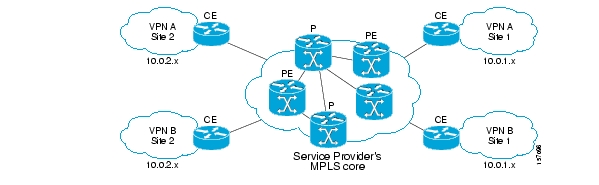
Some of the benefits of MPLS-based VPNs are seamless integration with customer intranets and increased scalability with numerous sites for each VPN and many VPNs for each service provider.
The MPLS/VPN BGP LEG solution consists of two components:
BGP LEG—A UNIX daemon process that runs the BGP protocol to determine the BGP routes. This process runs under the root privileges.
Subscriber Manager (SM)—The Subscriber Manager server stores subscriber information and updates the Service Control Engines (SCEs). The BGP adapter, an SM component, receives the routes from the BGP LEG and handles the adjustments to the regular login/logout operations.
The SM and the BGP LEG are different processes that run on the same machine. The connection between the components is based on the PRPC protocol.
The following diagram illustrates the MPLS/VPN BGP LEG solution:

The BGP LEG also supports receiving BGP updates from a Route Reflector (RR), instead of from each PE router separately. The BGP LEG can receive updates from a Route Reflector and from PEs that are not covered by the Route Reflector at the same time.
A VPN subscriber is a group of VPN sites. The following parameters define a VPN site:
The Provider Edge (PE) router that is connected to the VPN site. The IP address of the loopback interface identifies the router.
An identifier for the VPN Virtual Routing and Forwarding (VRF) table. Either the Route Distinguisher (RD) of the VRF or the Route Target (RT) that is used for exporting or importing routes
The PE router assigns MPLS labels for each VPN site. The BGP protocol uses the MPLS labels to publish the VPN routes to the other PE routers. The BGP LEG listens to the BGP traffic, extracts the MPLS label, and adds the label to the subscriber data in the SM database.
The VPN subscriber can be identified using either the Route Distinguisher (RD) attribute or the Route Target (RT) attribute. It is necessary to decide which attribute best reflects the VPN subscriber partitioning, and then configure the SM accordingly. Note that the configuration is global for all the subscribers, i.e. all subscribers must be identified by the same attribute.
The Route Distinguisher (RD) is most commonly used to identify the distinct VPN routes of separate customers who connect to the provider. Therefore, in most cases the RD is a good partition for the subscribers in the network. Since the RD is an identifier of the local VRF, and not the target VRF, it can be used to distinguish between VPN sites that transfer information to a common central entity (e.g. a central bank, IRS, Port Authority, etc.).
The Route Target (RT) is used to define the destination VPN site. Though it is not intuitive to define the VPN subscriber based on its destination routes, it might be easier in some cases. For example, if all the VPN sites that communicate to a central bank should be treated as a single subscriber, it is worthwhile to use the RT as the VPN identifier.
It is important to note that the configuration is global. Thus, if at some point in time, a certain VPN subscriber needs to be defined by RD, then all the VPN subscribers must be defined by RD as well. This is a point to consider when designing the initial deployment.
The following scenario depicts the operation of the MPLS/VPN mode:
The Subscriber Manager starts up.
BGP LEG establishes a PRPC connection to the Subscriber Manager.
The administrator imports the VPN subscribers to the Subscriber Manager using a CSV file. The administrator specifies the following properties for each VPN subscriber:
VPN subscriber name—Used as the subscriber name
A list of VPN sites. Each VPN site is defined by:
VPN ID—The RD or RT that identifies the VPN's VRF
The IP address of the loopback interface of the PE router
SM domain
A list of application properties. For example, the Service Control Application for Broadband (SCA BB) package ID, as described in the Cisco Service Control Application for Broadband (SCA BB) User Guide.
The administrator configures the BGP LEG by specifying the PE routers that should be connected to it.
PE routers distribute routing information to the BGP LEG.
The BGP LEG analyzes BGP sessions and extracts the relevant data, such as RD/RT, MPLS label, and the loopback IP of the PE router.
The BGP LEG updates the SM with the new information.
The Subscriber Manager updates its database with the new subscriber information and performs a login/logout operation to all of the SCE devices in the subscriber domain.
Note
The SM MPLS/VPN BGP LEG automatically refreshes the BGP connections to all the relevant PEs after adding subscribers to the SM.
The following list of terms and concepts are necessary to understand the MPLS/VPN BGP LEG, configuration, and operation. Additional information regarding other issues can be found in the Service Control Management Suite Subscriber Manager (SCMS SM) User Guide.
An exterior gateway protocol used on the Internet to provide loop-free routing between different autonomous systems.
In the context of MPLS/VPN, the BGP protocol is used to distribute the MPLS/VPN routes of a PE router to its neighboring PE routers.
A router on the service provider site that connects to the PE (Provider Edge) router in the MPLS core. The CE router only passes the message packet with the IP address and is not concerned with the MPLS/VPN label.
A software component that performs subscriber login and logout operations on the SM, which is used to handle dynamic subscriber integration.
A switching method that forwards IP traffic using a label. This label instructs the routers and the switches in the network where to forward the packets based on pre-established IP routing information.
A router in the service provider MPLS core that provides routing information between the customer router and the MPLS/VPN network. The PE router maintains a VRF (Virtual Routing and Forwarding) table for each customer site to determine how to route the packet.
An 8-byte value that is concatenated with an IPv4 prefix to create a unique VPN IPv4 prefix.
The RD uniquely identifies the VPN VRF within a PE router.
A network element in the service provider network that is used to distribute BGP routes to the service provider BGP-enabled routers. Route Reflectors provide a mechanism for both minimizing the number of update messages transmitted within the autonomous system and reducing the amount of data that is propagated in each message.
Used by the routing protocols to control import and export policies and to build arbitrary VPN topologies for customers.
The SM provides the option of partitioning SCE platforms and subscribers into subscriber domains. A subscriber domain is a group of SCE platforms that share a group of subscribers. Subscriber domains can be configured using the SM configuration file and can be viewed using the SM Command-Line Utility (CLU).
For additional information about domains and domain aliases, see the SCMS Subscriber Manager User Guide.
The Service Control solution requires a unique identifier for each subscriber. A subscriber ID represents a logical subscriber entity from the service provider perspective.
The SCE platform requires mappings between the network IDs (IP addresses) of the flows it encounters and the subscriber IDs. The SM database contains the network IDs that map to the subscriber IDs. The SCE network-ID-to-subscriber mappings are constantly updated from the SM database.
A technology for securely connecting a computer or network to a remote network over an intermediate network such as the Internet.
VPNs can use an insecure public network such as the Internet to connect two networks. They can also use an insecure public network to connect a network and a remote computer, or employ technologies such as tunneling, encryption, and authentication to secure the connection.
In general, a VRF includes the routing information that defines the VPN site that is attached to a PE router. A VRF consists of an IP routing table, a forwarding table, a set of interfaces that use the forwarding table, and a set of rules and routing protocols that determine what goes into the forwarding table.
This chapter describes the procedures for installing the SM MPLS/VPN BGP LEG software module. It also describes the uninstall procedure.
The SM MPLS/VPN BGP LEG is an external component that should be installed on the SM. The SM MPLS/VPN BGP LEG distribution is part of the SM LEG distribution.
The SM MPLS/VPN BGP LEG installation package includes a set of configuration files and the Command-Line Utility (CLU).
The SM MPLS/VPN BGP LEG can be installed only on Red Hat Linux platforms.
The following tables describes the contents of the SM MPLS/VPN BGP LEG distribution package supplied by Cisco:
Table 2.1. SM MPLS/VPN BGP LEG Distribution Package Contents
|
Path |
File Name |
Description |
|---|---|---|
|
DIST_ROOT/bgp_leg |
|
SM MPLS/VPN BGP LEG files |
|
|
bgp_leg.tar.gz |
SM MPLS/VPN BGP LEG distribution |
|
|
Install |
LEG installation procedure description |
|
|
install-bgp-leg.sh |
SM MPLS/VPN BGP LEG installation script |
|
|
linux-def.sh |
Linux specific definitions script |
|
|
sm-common.sh |
General installation script |
To install the SM MPLS/VPN BGP LEG on the SM machine:
Copy the SM LEG distribution file to the SM machine and extract it by performing the following operation:
> gunzip SM_LEG_3.0.3 Bbbb.tar.gz
> tar –xvf SM_LEG_3.0.3_Bbbb.tar.gz
> cd bgp_leg
Run the BGP LEG installation script:
#/install-bgp-leg.shThe installation script automatically installs the SM MPLS/VPN BGP LEG on the SM and runs the OS specific definitions scripts according to your installation's operating system.
Add a VCS resource for the BGP LEG (optional for cluster setups)
Note
The installation script must run under root privileges.
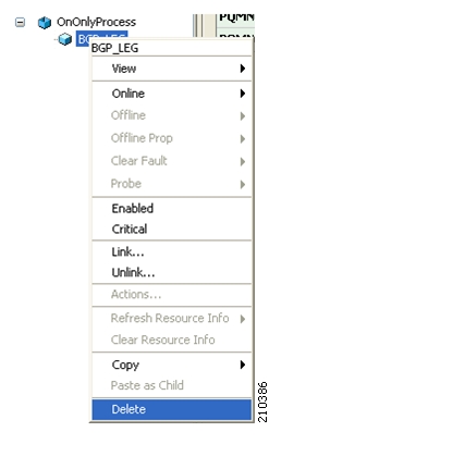
In a Subscriber Manager cluster topology, the Veritas Cluster Server (VCS) should monitor the BGP LEG process to verify that the process is running. To do so, you must configure the VCS with a resource that monitors and controls the LEG.
To add a BGP LEG resource:
Import the OnOnlyProcess agent's type from file:
/opt/VRTSvcs/bin/OnOnlyProcess/OnOnlyProcess.cf.Add an OnOnlyProcess resource called "BGP_LEG" to the service group.
Run the following command via telnet session on each one of the servers:
>ps -ea -o pid,s,argsLook for the line containing "bgpleg" in the text. This line contains the path and arguments of the BGP LEG to be used in the next step.
Define the following parameters:
OnlineCmd—Type the BGP LEG start command, for example:
/opt/pcube/sm/server/bin/p3bgp --startPathName—Type the BGP LEG process path (from the previous step), for example:
/opt/pcube/sm/server/addons/bgpleg/bgplegArguments—Type the BGP LEG process arguments (from the previous step). For example:
-launch /opt/pcube/sm/server/root/config/p3bgpleg.cfg.
Click OK.
The following figure displays the Add Resource window:
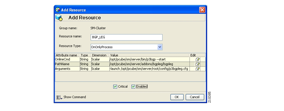
Note
The arguments line might seem shorter than the actual full argument value, which is perfectly acceptable.
This chapter explains how to configure the SM MPLS/VPN BGP LEG.
The SM MPLS/VPN BGP LEG is configured using the configuration file p3bgpleg.cfg file, which resides in the sm-inst-dir/sm/server/root/config directory (sm-inst-dir refers to the SM installation directory). The configuration file is loaded only upon the SM MPLS/VPN BGP LEG startup.
The configuration file holds the IP addresses of the PEs from which the routing information is gathered. When you reload the configuration file, all the BGP connections terminate and the BGP LEG waits for connections to be re-established from the IP addresses configured in the configuration file.
The configuration file consists of sections headed by a bracketed section title such as [General] for the general configuration section. Each section consists of one or more parameters having the format parameter=value. The number sign ("#") at the beginning of a line signifies that it is a comment.
This section describes the configuration file settings for each section.
The [General] section contains the following parameter:
as-numDefines the autonomous system number of the BGP LEG. This parameter is mandatory and has no default value. Possible values are
1to65535.max-route-burstDefines an estimation of the expected burst of routes upon PE connection/refresh-all.
This parameter sets the PRPC buffer size between the BGP LEG and the SM.
The parameter is mandatory and has a default value of 100K routes in the p3bgpcfg configuration file.
The [PE.xxxxxxxx] section holds the PE or Route Reflector information. Each PE section must include a unique PE/Route Reflector name. The section contains the following parameters:
accessDefines the IP address or addresses that the PE/Route Reflector accesses (in dotted notation). It is mandatory to configure at least one access IP address. Additional IP addresses, if needed, should be on the same line, separated by comma. The same IP address cannot appear in two PE sections.
as-numDefines the autonomous system number connected to the PE/Route Reflector. This parameter is not required. If not specified, the as-num defined in the
[General]section is used.
The following example illustrates the MPLS/VPN BGP LEG configuration file:
[General]
as-num=255
max-route-burst=100000
[PE.site104]
access=10.56.211.80, 10.0.1.2, 10.55.123.56
[PE.site110]
access=10.28.233.129
as-num=110
[PE.10.56.211.81]
access=10.56.211.81You must configure the Subscriber Manager to support the SM MPLS/VPN BGP LEG. The SM configuration file, p3sm.cfg contains a configuration section for MPLS/VPN called [MPLS/VPN]. The section contains the following parameters:
vpn_idDefines the BGP attribute that is used to identify the VPN subscribers.
Possible values for this parameter are
RDandRT.The default value is
RT.log_allDefines the logging level of the BGP LEG.
Possible values for this parameter are
trueorfalse.The default value is
false.If this parameter is set to
true, the SM logs all received BGP packets. Set this parameter totrueduring the integration/testing phase.
For further information on configuring the SM, see the Cisco SCMS Subscriber Manager User Guide.
This chapter describes how to manage MPLS/VPN subscribers.
You use a set of Command-Line Utilities (CLU) to control the SM. The p3subs is the CLU that manages the SM subscribers. A detailed description of the SM CLU can be found in the SCMS Subscriber Manager User Guide.
This chapter covers the information relevant for MPLS/VPN subscribers.
To add an MPLS/VPN subscriber, use the following CLU:
From the shell prompt, enter a command using the following general format:
p3subs --add--subscriber=Subscriber-name[--mpls-vpn=VPN-ID@PE-IP[,MORE]] [--property=property-name=value] [--domain=domain-name]
A set of [VPN-ID, PE-IP] pairs defines each subscriber. The VPN-ID is the RD or RT that identifies the subscriber, and the PE-IP is the loopback IP address of the PE router that is connected to the VPN site.
Note
You must add MPLS/VPN subscribers to the SM before starting the BGP LEG. Otherwise, the BGP labels of the subscribers will not be added to the SM, and you will have to send a route refresh request to the PE.
Note
To add multiple MPLS/VPN subscribers, prepare a CSV file containing the subscriber information, and use the CLU p3subsdb --import. The network-ID of the MPLS/VPN subscribers is VPN-ID@PE-IP, as described above.
To add a VPN site to an existing subscriber, use the following CLU:
From the shell prompt, enter a command using the following general format:
p3subs --set--subscriber=Subscriber-name[--mpls-vpn=VPN-ID@PE-IP]
This operation adds the VPN site (identified by the VPN-ID) behind the PE router (whose IP address is PE-IP) to the existing subscriber 'Subscriber-Name'.
To display an MPLS/VPN subscriber, use the following CLU:
From the shell prompt, enter a command using the following general format:
p3subs --show--subscriber=Subscriber-name
This operation has the following output:
Name: VPN1Domain: subscribersMappings:MPLS/VPN: 1:1000@1.1.1.1 (no BGP information)MPLS/VPN: 1:1001@1.1.1.1 label: 10 IP range: 10.1.1.1/24According to this output, the subscriber VPN1 has two VPN sites: 1:1000 and 1:1001. Both sites are behind the same PE whose IP address is 1.1.1.1. The VPN site 1:1000 did not receive any BGP routes. The VPN site 1:1001 received one BGP route with the label 10 corresponding to the subnet 10.1.1.1/24.
To remove an MPLS/VPN subscriber, use the following CLU:
From the shell prompt, enter a command using the following general format:
p3subs --remove--subscriber=Subscriber-name
This operation removes the entire subscriber from the SM including the entire VPN site and any received BGP updates.
To remove a VPN site from a subscriber, use the following CLU:
From the shell prompt, enter a command using the following general format:
p3subs --remove--subscriber=Subscriber-name--mpls-vpn=VPN-ID@PE-IP
This operation removes the VPN site (identified by VPN-ID) behind the PE router (whose IP address is PE-IP) from the subscriber 'Subscriber-Name'. It also removes all the BGP routes that were received for this VPN site.
The p3bgp utility controls the operation of the BGP LEG and displays its status. The command format is p3bgp <operation> [parameter]
The following table lists the p3bgp operations:
Table 5.1. p3bgp Operations
|
Operation |
Description |
|---|---|
|
--start |
Starts the BGP LEG |
|
--stop |
Stops the BGP LEG |
|
--restart |
Restarts the BGP LEG |
|
--status |
Displays a short status line for each PE/RR |
|
--show |
Displays a detailed status for a specific PE/RR |
|
--show-all |
Displays a detailed status for each PE/RR |
|
--refresh |
Sends a refresh request to specific PE/RR to receive updated information on all routes |
|
--refresh-all |
Sends a refresh request to all PE/RR to receive updated information on all routes. Use this operation when the PE/RR is disconnected from the LEG and you want to make sure that all the BGP information is propagated to the SCE boxes. The refresh is for new information only; obsolete labels are not checked for validity. |
|
--force-sync |
Used together with --refresh-all. Sends a refresh request to all PE/RR to receive updated information on all routes, and then synchronizes this information with all SCE boxes. After this operation is completed, the SCE boxes are updated with the BGP information. Use this operation when the PE/RR is disconnected from the LEG and you want to make sure that all the BGP information is propagated to the SCE boxes. This operation also makes sure that obsolete labels are removed from the SCE boxes. |
|
--load-config |
Loads the configuration file to the BGP LEG. This operation also restarts the BGP LEG. |
|
--help |
Displays the available p3bgp commands |
The following is an example of the p3bgp command-line utility using the status operation:
|
|
|
|
|
|
|
|
|
|
|
|
|
|
|
|
|
|
|
|
|
|
|
|
|
|
|
The following list is a description of the status operation output:
Peer IP—The IP of the PE/RR that is connected to the LEG
PE name—The name of the PE/RR as configured in the configuration file
Updates recv—A counter for all the BGP updates received from this PE/RR
Notify recv—A counter for all the BGP notifications received from this PE/RR
K.Alive sent—A counter for all the BGP keep alives sent to this PE/RR
K.Alive recv—A counter for all the BGP keep alives received from this PE/RR
Hold Time—The remaining time-out for the next keep alive
The following is an example of the p3bgp command line utility using the show operation on a specific PE router named PE101:
1 : PE101
connects : 1
recv UPDATE : 150
recv KEEPALIVE : 57
sent KEEPALIVE : 58
recv NOTIFY : 0
current holdtime : 157
TCP sndwnd : 16384
TCP rcvwnd : 87380
Connection up time : 0 Days, 1 Hrs, 7 Min, 59 Sec
refresh requests : 2
recv PE AddRoute messages : 2
send SM AddRoute messages : 10
send SM not connected : 0
BGP state : Established
The following list is a description of the show operation output:
connects—The number of successful connections established with this PE/RR since the LEG is up.
recv UPDATE—A counter for all the BGP updates received from this PE/RR
recv KEEPALIVE—A counter for all the BGP keep alives received from this PE/RR
sent KEEPALIVE—A counter for all the BGP keep alives sent to this PE/RR
recv NOTIFY—A counter for all the BGP notifications received from this PE/RR
current holdtime—The remaining time-out for the next keep alive
TCP sndwnd—The TCP send window buffer size
TCP rcvwnd—The TCP receive window size
Connection up time—The time since the connection to this PE/RR was established
refresh requests—A counter for the number of refresh requests requested for this PE/RR
recv PE AddRoute messages—A counter for BGP add-route messages received from the PE/RR
send SM AddRoute message—A counter for successful add routes invocations performed on the SM for this PE/RR
send SM not connected—A counter for SM invocations that were kept in an internal buffer due to disconnected SM
BGP state—The state of the BGP connection to this PE/RR