- Preface
- 1. General Overview
- 2. Introducing the Subscriber Manager
- 3. Installation and Upgrading
- Installation Overview
- Contents of Distribution Files
- Documentation
- System Requirements
- Installation Procedures
- Typical Installation
- Verifying that the Installation was Successful
- Configuring the Subscriber Manager
- Additional Installation Procedures
- Troubleshooting the Installation
- Installing an Application
- System Changes Made by Installation Scripts
- Upgrading
- Uninstalling
- 4. Configuration and Management
- SM Management and Configuration Methods
- Configuring a Subscriber Management Solution
- Using the CLU
- Informative Output
- Parsing CLU Operations and Options
- Reloading the SM Configuration (p3sm)
- Managing the SM (p3sm)
- Managing Subscribers, Mappings, and Properties (p3subs)
- Managing the Subscriber Database (p3subsdb)
- Viewing and Connecting Network Elements (p3net)
- Viewing Subscriber Domains (p3domains)
- Managing the Cable Support Module (p3cable)
- Installing an Application (p3inst)
- Viewing Information of the PRPC Interface Server (p3rpc)
- Managing a Cluster of Two SM Nodes (p3cluster)
- Managing the User Log (p3log)
- Viewing Statistics of the RADIUS Listener (p3radius)
- Utilities
- A. Configuration File Options
- Introduction
- Description of the Configuration File Options
- SM General Section
- SM High Availability Setup Section
- Subscriber State Persistency Section
- SM-LEG Failure Handling Section
- LEG-Domains Association Section
- Domain.XXX Section
- Default Domains Configuration Section
- Auto Logout Section
- Radius Listener Section
- Radius.NAS.XXX Section
- Radius.Property.Package Section
- Radius.Subscriber ID Section
- RPC.Server Section
- MPLS-VPN Section
- SCE.XXX Section
- FTP Section
- HTTP Tech-IF Section
- RDR Server Section
- Cable Adapter Section
- Data Repository Section
- B. Command-Line Utilities
- C. CPE as Subscriber in Cable Environment
- D. Troubleshooting
- Using the Troubleshooting Chapter
- General Errors
- General Setup Errors
- TimesTen Database Setup Errors
- Introduction
- TimesTen DSN Configuration—Cannot Find Requested DSN
- TimesTen DSN Configuration—Data Source Name Not Found
- TimesTen Database Settings—Cannot Connect to Data Source
- TimesTen Configuration Error—Not Enough Memory
- TimesTen Configuration Error—Incorrect Memory Definitions
- TimesTen Configuration Error—Cannot Create Semaphores
- TimesTen Configuration Error—Cannot Read Data Store File
- TimesTen Configuration Error—Data Store Space Exhausted
- Network Management Command Line Utility (p3net) Errors
- Subscriber Database Command Line Utility (p3subsdb) Errors
- Cable Support Command Line Utility (p3cable) Errors
- Configuration Errors
- E. Veritas Cluster Server Requirements and Configuration
This document is a guide to the configuration and management of the Subscriber Manager (SM) application. It contains explanations of relevant concepts and terminology in addition to instructions on how to install, configure, and use the SM.
Note
The guide assumes a basic familiarity with the telecommunications equipment and installation procedures, concepts of the Service Control Management Suite, the SCE 1000 and SCE 2000 platforms, and their related components.
This Cisco SCMS Subscriber Manager User Guide documents the application that processes subscriber records and maintains the subscriber database for use by the SCE platform. It contains instructions for installing the SM and the TimesTen database, editing and installing the configuration file, and managing the system using the Command-Line Utilities (CLU). It also specifies how to configure a Service Control deployment to support subscriber integration in its various forms.
|
Cisco Service Center Release |
Part Number |
Publication Date |
|---|---|---|
|
Release 3.0.5 |
OL-7199-05 |
November, 2006 |
Description of Changes
Changes to the RPC.Server sections of the configuration file to include PRPC server security level. See RPC.Server and RPC.Server Section.
Changes to p3rpc CLU. See p3rpc Utility.
Addition of formatting rules for the subscriber ID. See Subscriber ID.
Addition of case insensitivity to the subscriber ID. See SM General Section.
|
Cisco Service Center Release |
Part Number |
Publication Date |
|---|---|---|
|
Release 3.0.3 |
OL-7199-04 |
July, 2006 |
Description of Changes
Changes to upgrade procedure. See Upgrade Procedure.
Updated installation software requirements to include Red Hat 4.
|
Cisco Service Center Release |
Part Number |
Publication Date |
|---|---|---|
|
Release 3.0.3 |
OL-7199-03 |
May, 2006 |
Description of Changes
Updated installation software requirements to include Solaris 10 and Red Hat 4.
Updated installation procedures to reflect removal of support for TimesTen, DSNs, and Java.
Added new section covering upgrade procedure from version 3.0 to 3.0.3. See Upgrading from a Cluster Setup version 3.x.
Changes to the procedure to uninstall VCS agents. See Uninstalling VCS agents.
Added new sections detailing the RDR Server configuration. See RDR Server and RDR Server Section.
Added new section detailing MPLS-VPN configuration. See MPLS-VPN Section.
Added arguments for MPLS/VPN mappings. See Managing Subscribers, Mappings, and Properties (p3subs) and p3subs Utility
|
Release 3.0 |
OL-7199-02 |
December, 2005 |
This guide is intended for the system administrator and the networking or computer technician who is responsible for the on-site installation and configuration of the Subscriber Manager (SM) application. It is also intended for the operator who will be responsible for daily operations of the SM.
This guide covers the following topics:
|
Chapter |
Title |
Description |
|---|---|---|
|
Chapter 1 |
Presents an overview of the Cisco Service Control Solution and the SCE platform | |
|
Chapter 2 |
Describes the Subscriber Manager solution, the handling of subscribers, the fundamentals and management of the SM application | |
|
Chapter 3 |
Describes the installation and basic configuration procedures for the SM and how to perform an upgrade of the SM | |
|
Chapter 4 |
Describes the SM configuration and management procedures and how to use the Command-Line Utilities (CLU) | |
|
Appendix A |
Provides a description of all parameters that can be configured by using the Subscriber Manager configuration file | |
|
Appendix B |
Describes the Command-Line Utilities (CLU) that the SM uses to manage and maintain the application | |
|
Appendix C |
Deals with the special case when the Customer Premise Equipment (CPE) is considered as the subscriber in the Cisco Service Control solution for a cable environment, such as DSL and Wireless. | |
|
Appendix D |
Describes the error messages, probable causes, and solutions of the SM application | |
|
Appendix E |
Provides basic guidelines for the Veritas Cluster Server configuration in an SM cluster installation |
Use this Engage User Guide in conjunction with the following Cisco documentation:
Cisco Service Control Application for Broadband (SCA BB) User Guide
Cisco SCE 1000 or SCE 2000 platform User Guides
This document uses the following conventions:
|
Convention |
Description |
|---|---|
|
boldface font |
Commands and keywords are in boldface. |
|
italic font |
Arguments for which you supply values are in italics. |
|
[ ] |
Elements in square brackets are optional. |
|
{x | y | z} |
Alternative keywords are grouped in braces and separated by vertical bars. |
|
[x | y | z] |
Optional alternative keywords are grouped in brackets and separated by vertical bars. |
|
string |
A nonquoted set of characters. Do not use quotation marks around the string, or the string will include the quotation marks. |
|
|
Terminal sessions and information that the system displays are in |
|
|
Information you must enter is in |
|
|
Arguments for which you supply values are in |
|
< > |
Nonprinting characters, such as passwords, are in angle brackets. |
|
[ ] |
Default responses to system prompts are in square brackets. |
|
!, # |
An exclamation point (!) or a pound sign (#) at the beginning of a line of code indicates a comment line. |
Note
Means reader take note. Notes contain helpful suggestions or references to materials not covered in this manual.
Caution
Means reader be careful. In this situation, you might do something that could result in loss of data.
The following sections provide sources for obtaining documentation from Cisco Systems.
You can access the most current Cisco documentation on the World Wide Web at the following sites:
Cisco documentation and additional literature are available in a CD-ROM package that ships with your product. The Documentation CD-ROM is updated monthly and may be more current than printed documentation. The CD-ROM package is available as a single unit or as an annual subscription.
Cisco documentation is available in the following ways:
Registered Cisco Direct Customers can order Cisco Product documentation from the networking Products MarketPlace:
Registered Cisco.com users can order the Documentation CD-ROM through the online Subscription Store:
Nonregistered Cisco.com users can order documentation through a local account representative by calling Cisco corporate headquarters (California, USA) at 408 526-7208 or, in North America, by calling 800 553-NETS(6387).
If you are reading Cisco product documentation on the World Wide Web, you can submit technical comments electronically. Click Feedback in the toolbar and select Documentation. After you complete the form, click Submit to send it to Cisco.
You can e-mail your comments to bug-doc@cisco.com.
To submit your comments by mail, use the response card behind the front cover of your document, or write to the following address:
Attn Document Resource Connection Cisco Systems, Inc. 170 West Tasman Drive San Jose, CA 95134-9883
We appreciate your comments.
Cisco provides Cisco.com as a starting point for all technical assistance. Customers and partners can obtain documentation, troubleshooting tips, and sample configurations from online tools. For Cisco.com registered users, additional troubleshooting tools are available from the TAC website.
Cisco.com is the foundation of a suite of interactive, networked services that provides immediate, open access to Cisco information and resources at any time, from anywhere in the world. This highly integrated Internet application is a powerful, easy-to-use tool for doing business with Cisco.
Cisco.com provides a broad range of features and services to help customers and partners streamline business processes and improve productivity. Through Cisco.com, you can find information about Cisco and our networking solutions, services, and programs. In addition, you can resolve technical issues with online technical support, download and test software packages, and order Cisco learning materials and merchandise. Valuable online skill assessment, training, and certification programs are also available.
Customers and partners can self-register on Cisco.com to obtain additional personalized information and services. Registered users can order products, check on the status of an order, access technical support, and view benefits specific to their relationships with Cisco.
To access Cisco.com, go to http://www.cisco.com.
The Cisco Technical Assistance Center (TAC) website is available to all customers who need technical assistance with a Cisco product or technology that is under warranty or covered by a maintenance contract.
If you have a priority level 3 (P3) or priority level 4 (P4) problem, contact TAC by going to the TAC website http://www.cisco.com/tac.
P3 and P4 level problems are defined as follows:
P3—Your network is degraded. Network functionality is noticeably impaired, but most business operations continue.
P4—You need information or assistance on Cisco product capabilities, product installation, or basic product configuration.
In each of the above cases, use the Cisco TAC website to quickly find answers to your questions.
To register for Cisco.com, go to http://tools.cisco.com/RPF/register/register.do.
If you cannot resolve your technical issue by using the TAC online resources, Cisco.com registered users can open a case online by using the TAC Case Open tool at http://www.cisco.com/tac/caseopen.
If you have a priority level 1 (P1) or priority level 2 (P2) problem, contact TAC by telephone and immediately open a case. To obtain a directory of toll-free numbers for your country, go to http://www.cisco.com/warp/public/687/Directory/DirTAC.shtml.
P1 and P2 level problems are defined as follows:
P1—Your production network is down, causing a critical impact to business operations if service is not restored quickly. No workaround is available.
P2—Your production network is severely degraded, affecting significant aspects of your business operations. No workaround is available.
This chapter provides a general overview of the Cisco Service Control solution. It introduces the Cisco Service Control concept and the Service Control capabilities. It also briefly describes the hardware capabilities of the Service Control Engine (SCE) platform and the Cisco specific applications that together compose the total Cisco Service Control solution.
The Cisco Service Control solution is delivered through a combination of purpose-built hardware and specific software solutions that address various service control challenges faced by service providers. The SCE platform is designed to support classification, analysis, and control of Internet/IP traffic.
Service Control enables service providers to create profitable new revenue streams while capitalizing on their existing infrastructure. With the power of Service Control, service providers have the ability to analyze, charge for, and control IP network traffic at multigigabit wire line speeds. The Cisco Service Control solution also gives service providers the tools they need to identify and target high-margin content-based services and to enable their delivery.
As the downturn in the telecommunications industry has shown, IP service providers’ business models need to be reworked to make them profitable. Having spent billions of dollars to build ever larger data links, providers have incurred massive debts and faced rising costs. At the same time, access and bandwidth have become commodities where prices continually fall and profits disappear. Service providers have realized that they must offer value-added services to derive more revenue from the traffic and services running on their networks. However, capturing real profits from IP services requires more than simply running those services over data links; it requires detailed monitoring and precise, real-time control and awareness of services as they are delivered. Cisco provides Service Control solutions that allow the service provider to bridge this gap.
Service providers of any access technology (DSL, cable, mobile, and so on) targeting residential and business consumers must find new ways to get maximum leverage from their existing infrastructure, while differentiating their offerings with enhanced IP services.
The Cisco Service Control Application for Broadband adds a new layer of service intelligence and control to existing networks that can:
Report and analyze network traffic at subscriber and aggregate level for capacity planning
Provide customer-intuitive tiered application services and guarantee application SLAs
Implement different service levels for different types of customers, content, or applications
Identify network abusers who are violating the Acceptable Use Policy
Identify and manage peer-to-peer, NNTP (news) traffic, and spam abusers
Enforce the Acceptable Use Policy (AUP)
Integrate Service Control solutions easily with existing network elements and BSS/OSS systems
The core of the Cisco Service Control solution is the purpose-built network hardware device: the Service Control Engine (SCE). The core capabilities of the SCE platform, which support a wide range of applications for delivering Service Control solutions, include:
Subscriber and application awareness—Application-level drilling into IP traffic for real-time understanding and controlling of usage and content at the granularity of a specific subscriber.
Subscriber awareness—The ability to map between IP flows and a specific subscriber in order to maintain the state of each subscriber transmitting traffic through the SCE platform and to enforce the appropriate policy on this subscriber’s traffic.
Subscriber awareness is achieved either through dedicated integrations with subscriber management repositories, such as a DHCP or a Radius server, or via sniffing of Radius or DHCP traffic.
Application awareness—The ability to understand and analyze traffic up to the application protocol layer (Layer 7).
For application protocols implemented using bundled flows (such as FTP, which is implemented using Control and Data flows), the SCE platform understands the bundling connection between the flows and treats them accordingly.
Application-layer, stateful, real-time traffic control—The ability to perform advanced control functions, including granular BW metering and shaping, quota management, and redirection, using application-layer stateful real-time traffic transaction processing. This requires highly adaptive protocol and application-level intelligence.
Programmability—The ability to quickly add new protocols and easily adapt to new services and applications in the ever-changing service provider environment. Programmability is achieved using the Cisco Service Modeling Language (SML).
Programmability allows new services to be deployed quickly and provides an easy upgrade path for network, application, or service growth.
Robust and flexible back-office integration—The ability to integrate with existing third-party systems at the Service Provider, including provisioning systems, subscriber repositories, billing systems, and OSS systems. The SCE provides a set of open and well-documented APIs that allows a quick and robust integration process.
Scalable high-performance service engines—The ability to perform all these operations at wire speed.
The SCE family of programmable network devices is capable of performing application-layer stateful-flow inspection of IP traffic, and controlling that traffic based on configurable rules. The SCE platform is a purpose-built network device that uses ASIC components and RISC processors to go beyond packet counting and delve deeper into the contents of network traffic. Providing programmable, stateful inspection of bidirectional traffic flows and mapping these flows with user ownership, the SCE platforms provide real-time classification of network usage. This information provides the basis of the SCE platform advanced traffic-control and bandwidth-shaping functionality. Where most bandwidth shaper functionality ends, the SCE platform provides more control and shaping options, including:
Layer 7 stateful wire-speed packet inspection and classification
Robust support for over 600 protocols and applications, including:
General—HTTP, HTTPS, FTP, TELNET, NNTP, SMTP, POP3, IMAP, WAP, and others
P2P file sharing—FastTrack-KazaA, Gnutella, BitTorrent, Winny, Hotline, eDonkey, DirectConnect, Piolet, and others
P2P VoIP—Skype, Skinny, DingoTel, and others
Streaming and Multimedia—RTSP, SIP, HTTP streaming, RTP/RTCP, and others
Programmable system core for flexible reporting and bandwidth control
Transparent network and BSS/OSS integration into existing networks
Subscriber awareness that relates traffic and usage to specific customers
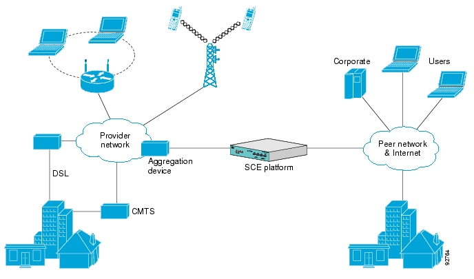
The following diagram illustrates a common deployment of an SCE platform in a network.
Service configuration management is the ability to configure the general service definitions of a service control application. A service configuration file containing settings for traffic classification, accounting and reporting, and control is created and applied to an SCE platform. The SCA BB application provides tools to automate the distribution of these configuration files to SCE platforms. This simple, standards-based approach makes it easy to manage multiple devices in a large network.
Service Control provides an easy-to-use GUI to edit and create these files and a complete set of APIs to automate their creation.
The Cisco Service Control solution includes a complete management infrastructure that provides the following management components to manage all aspects of the solution:
Network management
Subscriber management
Service Control management
These management interfaces are designed to comply with common management standards and to integrate easily with existing OSS infrastructure.
Cisco provides complete network FCAPS (Fault, Configuration, Accounting, Performance, Security) Management.
Two interfaces are provided for network management:
Command-Line Interface (CLI)—Accessible through the Console port or through a Telnet connection, the CLI is used for configuration and security functions.
SNMP—Provides fault management (via SNMP traps) and performance monitoring functionality.
Where the SCA BB enforces different policies on different subscribers and to track usage on an individual subscriber basis, the Cisco Service Control Management Suite (SCMS) Subscriber Manager (SM) may be used as middleware software for bridging between the OSS and the SCE platforms. Subscriber information is stored in the SM database and can be distributed between multiple platforms according to actual subscriber placement.
The SM provides subscriber awareness by mapping network IDs to subscriber IDs. It can obtain subscriber information using dedicated integration modules that integrate with AAA devices, such as Radius or DHCP servers.
Subscriber information may be obtained in one of two ways:
Push Mode—The SM pushes subscriber information to the SCE platform automatically upon logon of a subscriber.
Pull Mode—The SM sends subscriber information to the SCE platform in response to a query from the SCE platform.
The Cisco Service Control solution generates usage data and statistics from the SCE platform and forwards them as Raw Data Records (RDRs), using a simple TCP-based protocol (RDR-Protocol). The Cisco Service Control Management Suite (SCMS) Collection Manager (CM) software implements the collection system, listening in on RDRs from one or more SCE platforms and processing them on the local machine. The data is then stored for analysis and reporting functions, and for the collection and presentation of data to additional OSS systems such as billing.
The Subscriber Manager (SM) is a middleware software component that supplies subscriber information for multiple SCE platforms in deployments where dynamic subscriber awareness is required. It does this in one of two ways:
By pre-storing the subscriber information
By serving as a stateful bridge between an AAA system or a provisioning system and the SCE platforms
The SCE platforms use subscriber information to provide subscriber-aware functionality, per-subscriber reporting, and policy enforcement.
Some Cisco Service Control solutions can also operate without subscriber awareness:
Subscriber-less—Control- and link-level analysis functions are provided at a global device resolution.
Anonymous subscriber—The system dynamically creates “anonymous” subscribers per IP address. User-defined IP address ranges may then be used to differentiate between anonymous subscribers policies.
Static subscriber awareness—Subscriber awareness is required, but allocation of network IDs (mainly IP addresses) to subscribers is static.
In these three modes, the SCE platform handles all subscriber-related functionality and an SM module is not required.
Note
Starting with SM version 2.2, you can configure the SM to operate either with or without a cluster of two SM nodes. The added functionality when operating in a cluster topology provides powerful new features such as fail-over and high availability. (For definitions of italicized terms, see the Glossary of Terms.) The information in most of this chapter is applicable whether using a cluster or not. However, for clarity, information that is applicable only when using a cluster is presented separately at the end of this chapter, in the section Subscriber Manager Fail-Over.
A subscriber is defined as a managed entity on the subscriber side of the SCE platform, to which accounting and policy are applied individually. The subscriber side of the SCE platform is the side of the SCE platform that points to the access or downstream part of the topology, as opposed to the network side, which points to the core of the network.
The SM addresses the following issues in allowing dynamic subscriber awareness:
Mapping—The SCE platform encounters flows with network IDs (IP addresses) that change dynamically, and it requires dynamic mapping between those network IDs and the subscriber IDs. The SM database contains the network IDs that map to the subscriber IDs. This is the main functionality of the SM.
Policy—The SM serves as a repository of policy information per subscriber. The policy information may be preconfigured to the SM, or dynamically provisioned when the mapping information is provided.
Capacity—The SCE platform or platforms may need to handle (over time) more subscribers than they can concurrently hold. In this case, the SM serves as an external repository for subscriber information, while the SCE platform is introduced only with the online or active subscribers.
Location—The SM supports the functionality of sending subscriber information only to the relevant SCE platforms, in case such functionality is required. This is implemented using the domains mechanism or the Pull mode (see Pull Mode).
The SM database (see SM Database) can function in one of two ways:
As the only source for subscriber information when the SM works in standalone mode
As a subscriber information cache when the SM serves as a bridge between a group of SCE devices and the customer Authentication, Authorization, and Accounting (AAA) and Operational Support Systems (OSS).
The following figure shows the flow of subscriber information through the SM.
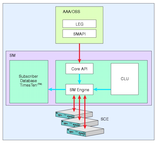
The flow takes place as follows:
Subscriber information enters the SM in one of two ways:
Automatically upon the subscriber going online—A Login Event Generator (LEG) software module that integrates with the customer AAA system (such as DHCP Server, RADIUS, or Network Access System (NAS)) identifies a subscriber login event, and sends it to the SM by using the SM API.
Manual setup—Subscriber information is imported into the SM from a file or by using the Command-Line Utilities (CLU).
Automatic and manual modes can be combined. For example, all subscribers may be loaded to the SM via manual setup, and a subset of the subscriber record (domain, network ID, and so on) changed automatically through the SM API.
In automatic mode, the SCMS SM Java or C/C++ APIs are used for delegating subscriber information to the SM (see the Cisco SCMS SM Java API Programming Guide or the Cisco SCMS SM C/C++ API Programming Guide).
The SM Engine:
Stores subscribers in the subscriber database
Introduces subscriber information to SCE Platforms
The information may be passed automatically to the SCE platform, or it may reside in the SM database until requested by the SCE platform.
The SM may be configured with more than one SCE platform. These SCE platforms may be grouped into domains. Each domain represents a group of SCE platforms that serve the same group of subscribers.
The subscribers of the service provider may be divided into the following logical types (at any given moment):
Offline subscriber—A subscriber that currently does not have any IP address and as such does not generate any IP traffic. Such subscribers are not stored in the SCE platform.
Online subscriber—A subscriber that is currently online.
At any particular time, a certain number of online subscribers will be idle, that is, connected to the service provider but not generating any IP traffic.
Active subscriber—An online subscriber that is actually generating IP traffic (such as by browsing the Internet or downloading a file).
In addition, the total number of subscribers is all the subscribers whose IP traffic might be traversing through the SCE platforms in a specific deployment.
There are four general scenarios for a network system using the SCE platforms:
Total number of subscribers can be statically stored in a single SCE platform.
This is the simplest, most reliable scenario. It may not require the use of the SM.
Total number of subscribers exceeds the capacity of the SCE platform, but the number of online subscribers predicted at any time can be statically stored in the SCE platform.
It is recommended to use the SM in Push mode. See Push Mode.
Number of online subscribers exceeds the capacity of the SCE platform, but the number of active subscribers predicted at any one time can be statically stored in the SCE platform.
The SM must be used in Pull mode. See Pull Mode.
Number of active subscribers predicted at any one time exceeds the capacity of the SCE platform.
Multiple SCE devices must be installed to divide the subscribers among the SCE platforms. If the system is divided into domains (see Domains), so that the SM knows in advance to which SCE platform a particular subscriber should be sent, Push mode may be used. Otherwise, Pull mode is required.
For specific scenarios using the SM with multiple servers and/or SCE platforms, see System Configuration Examples.
The SM uses a commercial relational database from TimesTen, optimized for high performance and with a background persistency scheme. The In-Memory Database efficiently stores and retrieves subscriber records.
A subscriber record stored in the SM Database (SM-DB) consists of the following components:
Subscriber name (key)—A string identifying the subscriber in the SM. Maximum length: 40 characters. This can be case-sensitive or case-insensitive depending on the configuration file. By default, the database is case-sensitive. If the database is case-insensitive, the SM will convert the name to lower case when updating or querying the database.
Domain (secondary key)—A string that specifies which group of SCE devices handles this subscriber.
Subscriber network IDs (mappings)—A list of network identifiers, such as IP addresses or VLANs. The SCE uses these identifiers to associate network traffic with subscriber records.
Subscriber policy—A list of properties that instruct the SCE what to do with the network traffic of this subscriber. The content of this list is application specific.
Subscriber state (for example, quota used)—A field that encodes the subscriber state, recorded by the last SCE, to handle the network traffic of this subscriber.
You can access the subscribers using one of two indexes:
Subscriber name
Subscriber name + domain
Note that in cluster redundancy topology, the active machine database replicates the subscriber data to the standby machine database. For additional information, see the Subscriber Manager (SM) Fail-Over section.
The Subscriber ID is a string representing a subscriber that is a unique identifier for each subscriber from the customer perspective. For example, it may represent a subscriber name or a CM MAC address. This section lists the formatting rules of a subscriber ID.
It may contain up to 64 characters. The following characters may be used:
|
Alphanumerics |
$ (dollar sign) |
. (period or dot) |
_ (underscore) |
|
- (minus sign or hyphen) |
% (percent sign) |
/ (slash) |
~ (tilde) |
|
! (exclamation mark) |
& (ampersand) |
: (colon) |
' (apostrophe) |
|
# (number sign) |
() (parentheses) |
@ (at sign) |
|
For example:
String subID1="john";
String subID2="john@yahoo.com";
String subID3="00-B0-D0-86-BB-F7";Use the SM API for:
Altering the fields of an already existing subscriber record
Setting up new subscribers in the SM
Performing queries
The SM API is provided in C, C++, and Java. It serves as the bottom-most layer of every LEG.
SM API programmer references are provided in the Cisco SCMS SM C/C++ API and the Cisco SCMS SM Java API Programmer Guides.
The SM Login Event Generators (LEGs) are software components that use the SM API to generate subscriber-record update messages (such as login/logout) and send them to the SM. LEGs are usually installed with AAA/OSS platforms, or with provisioning systems. They translate events generated by these systems to Cisco Service Control subscriber update events.
The unique functionality of each LEG depends on the specific software package with which it interacts. For example, RADIUS LEGs, DHCP LEGs, or some provisioning third party system LEGs may be implemented. LEGs can set up subscribers or alter any of the fields of an existent subscriber record.
You can connect multiple LEGs to a single SM. Conversely, a single LEG can generate events for multiple domains.
As illustrated in the figure in Flow of Subscriber Information, the SM introduces subscriber data to the SCE platforms. This operation functions in one of two modes:
Push—This is the simpler and recommended mode.
Pull—Use this mode only in special cases, as explained below.
Push or Pull mode is configured for the entire SM system.
For information detailing the configuration of the subscriber integration modes, see the SM General Section.
In Push mode, immediately after adding or changing a subscriber record, the SM distributes, or pushes, this information to the relevant SCE platforms, as determined by the subscriber domain. When the subscriber starts producing traffic through the SCE platform, it is ready with the required subscriber information.
In some scenarios, factors such as capacity limitations make it impossible to use Push mode.
Note
Use Push mode only if all online subscribers associated with a domain can be loaded simultaneously into all the SCE platforms in the domain.
In Pull mode, the SCE platforms are not notified in advance of subscriber information. When an SCE platform cannot associate the IP traffic with a subscriber, it will request, or pull, the information from the SM.
The advantage of Pull mode is that there is no need to know in advance which SCE platform serves which subscriber.
The disadvantages of Pull mode are:
Increased communication in the SM-SCE link
Increased load on the SM, as it processes incoming requests from both the SCE device and the LEG.
Note
By default, the SCE does not request subscriber information from the SM. You must configure anonymous groups in the SCE for the set of IP ranges that should be requested from the SM. See the SCE User Guide for more details on anonymous subscriber groups.
Note
Pull mode must be used when all online subscribers associated with a domain exceed the capacity of the SCE platforms in the domain (but the number of active subscribers can still be loaded into the SCE platforms in the domain).
The following table summarizes the differences between the Push mode and Pull mode:
Table 2.1. Differences Between Push Mode and Pull Mode
|
Aspect of Use |
Push Mode |
Pull Mode |
|---|---|---|
|
When to use |
For simple provisioning of subscriber information to the SCE platform |
For real-time, on-demand subscriber information retrieval Used in large scale deployments:
|
|
Functional flow at access time |
|
|
|
Subscriber information at the SCE platform |
SCE platform always has current subscriber information:
|
SCE gets subscriber information on demand |
The SM provides the option of partitioning SCE platforms and subscribers into subscriber domains.
The motivation for the domains concept is for enabling a single SM to handle several separate network sections, and for better control of subscriber introduction to the SCEs.
A subscriber domain is a group of SCE platforms that share a group of subscribers. The subscriber traffic can pass through any SCE platform in the domain. A subscriber can belong to only a single domain. Usually a single SCE platform serves a subscriber at any given time.
Domains are managed differently in the Push and Pull modes:
In Push mode, all the subscribers in a subscriber domain are sent to all SCEs in the domain. The main reason for the number of SCE platforms in a single domain is redundancy.
In Pull mode, the pull requests are handled only for subscribers in the domain of the pulling SCE platform. In Pull mode, usually a single domain covers all the subscribers.
The system is configured with one default subscriber domain called “subscribers”. When adding an SCE platform to the SM, it is automatically added to this default domain, unless otherwise specified. Subscribers are also associated with this default subscriber domain, unless otherwise specified. To associate a subscriber with a different domain, first define this domain in the configuration file, and then explicitly specify it when adding the subscriber to the SM. To associate an SCE platform with a non-default subscriber domain, edit and reload the configuration file. For more information, see Chapter 4, Configuration and Management.
A communication failure may occur either on the LEG-SM communication link or on the SMSCE communication link. A communication failure may occur due to a network failure or because the SCE, SM, or LEG has failed. High availability and recovery from an SM failure are discussed in SM Cluster.
When configuring the system, you should consider three issues related to communication failures:
Communication failure detection—A timeout after which a communication failure is announced
Communication failure handling—The action to be taken when communication on the link fails
Communication failure recovery—The action to be taken when communication on the link resumes
Either one of two mechanisms detects a communication failure:
Monitoring the TCP socket connection state. All peers do the monitoring.
Using a keep-alive mechanism at the PRPC protocol level
There are two configuration options for handling communication failures:
Ignore communication failures
Erase the subscriber mappings in its database and start handling flows without subscriber awareness
Erasing the mappings in the database is useful when you want to avoid incorrect mappings of subscribers to IP addresses. This configuration is implemented by requesting to clear all mappings upon failure.
The SM supports high availability using the Veritas Cluster Server (VCS) technology. In a high availability topology, the SM software runs on two machines, designated as the active machine and the standby machine. Subscriber data is continuously replicated from the active to the standby machine, ensuring there is minimal data loss in case of active SM failure. When the active machine fails, the standby machine discovers the failure and becomes active. For additional information, see the Subscriber Manager Fail-Over section.
SM management includes configuration, fault management, logging management, and performance management.
Configure the SM using the following:
Configuration file (
p3sm.cfg)—For setting all configuration parameters of the Subscriber Manager.
Note
Changes that you make in the configuration file take effect only when you load the configuration file using the Command-Line Utilities (CLU) or when you restart the SM.
For a detailed description of this file, see Appendix A, Configuration File Options.
Command-Line Utilities (CLU)—For ongoing subscriber management and monitoring of the SM. CLU commands are shell tools that you can use to manage subscribers, install or update applications, retrieve the user log, and load the configuration file when updated.
For a complete description of the Command Line Utilities, see Appendix B, Command-Line Utilities.
The CLU can be invoked locally, through a Telnet (or SSH) session to the SM hosting platform.
Use the SM user log files for logging, fault, and performance management. The log file contains information regarding system events, failures, and periodic system performance reports.
You can configure the SM to operate with or without a cluster. The added functionality when operating in a cluster topology provides powerful new features such as fail-over and high availability. (For definitions of italicized terms, see the Glossary of Terms.)
This section describes topics that are related to using the Subscriber Manager together with clusters and redundancy.
As the Subscriber Manager plays a critical role in the Cisco SCA BB solution that is deployed in tier-one service provider environments, it also supports, starting with SM version 2.2, a fail-over operational mode. This feature minimizes system downtime that is caused by SM failure (as further discussed in Overview).
This section introduces various concepts that are related to using a cluster of two SM nodes in a fail-over operational mode.
Note
For the purposes of this section, it is assumed that the reader is familiar with the Veritas Cluster technology.
The fail-over scheme that is implemented in the SM is based on the Veritas cluster technology. The cluster includes two machines, each of them running SM TimesTen and Veritas software. The Veritas Cluster Server (VCS) software consolidates the SMs and exposes a single entity by providing a single virtual IP address for the entire cluster.
The cluster software distinguishes an active and a standby machine: the active machine “owns” the virtual IP address and all network connections, while the standby machine is passive until a fail-over occurs. At fail-over, the IP address is passed from the failing server to the backup server, which becomes activated and re-establishes all network connections.
When a fail-over occurs, the LEGs lose their connection with the failed SM, and reconnect to the activated (backup) SM and retransmit their uncommitted messages. The activated SM connects to the SCE platforms and performs an SCE resynchronization.
The TimesTen database replication agent constantly replicates the SM database from the active node to the standby node. This enables a fast fail-over from one SM to another, since the subscriber data in the activated machine is always valid. The two SM nodes do not communicate except for passing the subscriber data.
The VCS uses software components called “cluster agents” to monitor and control the state of resources such as Network Interface Cards (NICs), disks, IP addresses, and processes. Cisco supplies cluster agents to monitor the SM and the TimesTen database daemon and replication agent.
As part of the cluster operation, the TimesTen database daemon and replication agents are up and running regardless of the fail-over state. The SM Veritas agent monitors the daemon and the replication agent process. In case one of them fails, a fail-over takes place.
Note
The SM software configuration on both the active and the standby machines must be identical. Apply the same configuration file and the same application PQI module to both machines.
The following sections describe these concepts in further detail.
The two SM nodes operate in hot-standby mode, where at any given time one node (the active node) receives and processes all the SM events, while the other node (the standby node) waits and is ready to go into operation on fail-over. For enabling seamless fail-over and for minimizing the fail-over time, the two SM nodes operate without an external storage device.
During the normal operation of the cluster, the active node (selected by the cluster):
Performs all SM functionality of a non-cluster environment
Provides “health” information for the cluster agent
Periodically replicates its subscriber database to the standby node
On the standby node, both the SM and the TimesTen software are running:
The SM is fully configured. (It is applied with the same configuration file and PQI application module as the active node, but does not interfere with the active node’s work.)
The SM connects to the TimesTen database, but does not connect to the LEG and the SCE devices.
The TimesTen software is operating as a replication client for the subscriber database, receiving and applying updates from the active node’s TimesTen software.
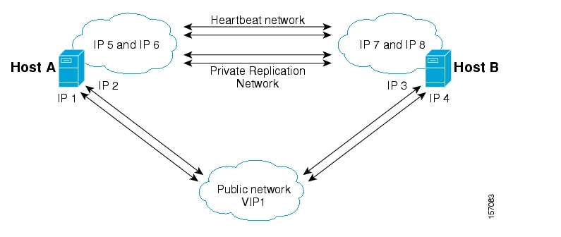
The following figure depicts an SM cluster configuration in a topology with a redundant AAA server and two SCE 2000 platforms that are cascaded for redundancy.
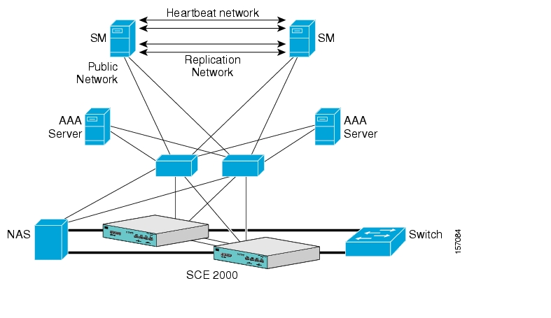
As already mentioned, an SM fail-over topology includes two SM nodes connected in a cluster scheme.
Two dedicated (private) redundant networks interconnect the two nodes:
Heartbeat network—Used by the Veritas Cluster Server to perform cluster monitoring and control.
Replication network—Used by the replication process to pass the subscriber records.
The two nodes should be located in the same site, where the heartbeat network is implemented using back-to-back connectivity between the two nodes or via redundant switches. Each node in the cluster has redundant network paths (NICs) connecting it to all of the external entities with which the SM communicates (AAA, LEG, SCE).
Each node in the cluster has a minimum of six Ethernet NICs, where
Two NICs are used for the (private) heartbeat network
Two NICs are used for the (private) replication network
Two NICs are used for the public network (connectivity to SCEs and LEGs, and management of the SM).
The cluster has a virtual IP (VIP) address used for communication with the external entities. Each node in the cluster has also an IP address for administration of the node/cluster, as well as an IP address for replication use.
Upon failure of the primary NIC of the public network, there is a fail-over to the secondary NIC on the same node, keeping the same IP addresses (VIP1), with no fail-over of the cluster. Upon failure of the primary NIC of the replication or heartbeat networks, there is fail-over to the secondary NIC on the same node, keeping the same IP addresses (VIP2 and VIP3), with no fail-over of the cluster.
The following diagram illustrates the usage of the regular and virtual IP addresses used in cluster configuration:
Administration of the nodes uses IP1/IP2 and IP3/IP4 respectively.
The cluster IP address for external clients over the public network uses VIP1.
For further information about replication IP configuration, see Appendix E, Veritas Cluster Server Requirements and Configuration.
During normal operation, the Veritas Cluster Server mechanism automatically selects one of the SM servers to be active and the other to be standby.
The active SM server performs all the normal SM functionality. The two servers maintain the heartbeat mechanism between them, and the active server continuously replicates the subscriber database to the standby server’s database.
The standby SM server acts as a hot-standby machine, so it is completely ready for taking over (becoming activated) in a minimal fail-over time.
The following types of failures trigger the fail-over mechanism:
SM application failure, including failure of the TimesTen database.
Failure of the TimesTen daemon of the TimesTen replication process.
SUN server failure, due to failure of one of the resources of the server; for example, failure of both of the public network NICs.
Manual activation of fail-over.
Note
Communication failure does not cause a fail-over if there is a redundant NIC. Therefore, because each SUN machine has two NICs for connecting to external devices, a failure of one of the NICs merely causes switching to the redundant NIC, without activating the fail-over mechanism.
After detecting a failure, the standby SM becomes activated, and the following occurs:
The activated SM takes over the IP resources of the virtual IP mechanism.
The LEGs reconnect to the activated SM.
The activated SM creates IP connections with the SCEs and resynchronizes with them.
The activated SM starts processing information that is sent from the different LEGs and forwards it to the SCEs.
Different types of failures require different triggering for the recovery procedure. Some failures may recover automatically such as intra-node ports link-failure, which recovers automatically when the link revives, while others may need manual intervention.
Recovery may take place when an SM that experienced a failure is self-recovered or after it was replaced (if needed). The purpose of the recovery procedure is to take the cluster back to a fully functional mode. When the recovery procedure ends, the behavior is the same as it was after installation.
The failed SM server is recovered manually or automatically, according to the type of failure that occurred. The recovery procedures, and when they are used, are described in the following sections.
Recovering from a machine reboot is a fully automatic recovery process, where the failed SM server reboots, and after establishing a connection with the other server and synchronizing the databases, the cluster of the two SM servers is ready again for fail-over operation.
The following steps are automatic steps:
The reboot process is run on the node.
VCS makes the node standby.
The node boots.
VCS establishes intra-node communication and the new node joins the cluster.
The TimesTen database replication process is started from the point before the reboot.
The SM in the recovered server is ready after the database recovery process is running and the SM moves from Init state to Standby state.
Replacing the server is necessary when the machine has an unrecoverable physical failure. A new machine that is installed with fresh SM, TimesTen, and VCS installations replaces the server.
Replacing the server is a manual recovery, where the failed SM server is physically replaced. After connecting the new SM server to the network, configuring it and synchronizing the two databases, the cluster of the two SM servers is ready again for fail-over operation.
To manually replace the server:
Connect a new server to the inter-node ports and intra-node ports (but leave the network ports disconnected).
Basic network and cluster configurations—perform manually (the first time).
Copy the configuration files from the active node.
Use the following CLU command if you only need to copy the
p3sm.cfgfile:p3sm–-load-config –-remote=<NEW-SM_IP>.Perform the TimesTen database duplication operation. See Database Duplication Recovery.
Start the VCS operation on the recovered node.
Connect the network ports.
The SM in the recovered server is ready after the database recovery process is completed and the SM moves from Init state to Standby state.
Database duplication recovery is a manual recovery, which is needed when the standby node database loses synchronization with the active node database. Loss of synchronization can occur when one of the SM machines is replaced or when the replication process on the active node fails to replicate all of the data inserted to its database (replication NICs were disconnected).
To perform the database duplication recovery (in standby node):
Stop the cluster server (VCS) monitoring of the resources. Use the VCS CLU
hastop -localcommand to stop the VCS.Stop the SM, so it will not be affected by clearing the database. Use the CLU command
p3sm–-stop.Stop the replication agent. Use the CLU command
p3db–-rep-stop.Destroy the database. Use the CLU command
p3db–-destroy-rep-db.Duplicate the remote database to the local machine. Use the CLU command
p3db–-duplicate.Start the cluster server monitoring of the resources (use the VCS CLU
hastartcommand), which will automatically start the replication process and the SM.
The two SM servers are configured using Command-Line Utilities and a configuration file (see Chapter 4, Configuration and Management and Configuring a Subscriber Management Solution). The actual configuration is performed for the active SM and then manually replicated for the standby SM.
To perform configuration duplication:
Establish an FTP connection between the active and standby machines.
Copy the configuration file from
~pcube/sm/server/root/config/p3sm.cfgon the active node to the standby node, and apply the SM configuration file by using the CLU commandp3sm–-load-config.Alternatively, you can replicate the SM configuration file to the standby machine by running the CLU command
p3sm–-load-config -–remote=<NEW-SM_IP>on the active machine.Copy the application PQI file you installed on the active node to the standby node.
Install the PQI file. Use the CLU command
p3inst --install -f<PQI file path>.If you have made changes in the database-related configuration files, copy the files to
/etc/system(for Solaris) or to/etc/sysctl.conf(for Linux), and/var/TimesTen/sys.odbc.inifrom the active node to the standby node.
Note
If you perform Step 5 (copying files), a reboot of the standby node is required.
Note
If the database is located in different directories in the two nodes, then the files sys.odbc.ini in both nodes are not identical and the actual parameter changed in the file must be copied.
Configure and administer the Veritas Cluster Server using Veritas tools.
Notifications are enabled through SNMP traps that the Veritas Cluster Server provides. The Veritas Cluster Server supports SNMP traps such as:
Fatal failure detected (local or remote)
Secondary node starts fail-over procedure
Secondary node is operational (end of fail-over)
This chapter describes how to install the Cisco Service Control Management Suite Subscriber Manager (SCMS SM), in addition to how to upgrade and uninstall. This chapter also discusses topics related to installation, upgrading, and uninstalling.
Installing the SM is an automated process. It consists of executing an installation script residing on the root of the SM distribution files supplied by Cisco.
Note
For Solaris: The procedure also requires modifying the /etc/system file. Do this manually or use some other automated utility.
Note
For Linux: The procedure also requires modifying the /etc/sysctl.conf file. Do this manually or use some other automated utility.
The installation procedure installs the following components:
SM and Command-Line Utilities (CLU)
TimesTen database and DSN
Java Runtime Environment (JRE)
SM Veritas Cluster Agents
The installation procedure also includes:
Setting up a pcube user and group
Adding startup and shutdown scripts
System configuration for TimesTen (performed manually or using a script)
Replication scheme setting (performed by running a CLU). (Relevant only for cluster setups).
After completing installation and configuration, you can use the SM to introduce subscribers to the system.
The SCMS SM components are supplied in three distribution files:
SM for Solaris
SM for Linux
Login Event Generators (LEGs)
Each distribution file is supplied as a tar file, which is compressed by gzip and has an extension of .tar.gz. The following table lists the contents of the SM installation distribution files for Solaris and Linux.
Table 3.1. Contents of SM Distribution Files
|
Path |
Name |
Description |
|---|---|---|
|
DIST_ROOT |
|
Cross-platform files |
|
|
hooks.sh |
User-defined function for upgrade |
|
|
install |
Typical installation procedure description |
|
|
install-dsn.sh |
TimesTen DSN configuration script |
|
|
installjava.sh |
JRE installation script |
|
|
install-sm.sh |
SM installation script |
|
|
install-tt.sh |
TimesTen installation script |
|
|
install-vcs-agents.sh |
VCS agents installation script |
|
|
linux-def.sh |
Linux-specific definitions (only in the Linux distribution file) |
|
|
solaris-def.sh |
Solaris-specific definitions (only in the Solaris distribution file) |
|
|
MANIFEST |
CD information |
|
|
p3sm.sh |
Startup and shutdown script |
|
|
Prerequisites |
System minimal requirements list |
|
|
sm-common.sh |
General installation script |
|
|
sm-dist.tar.gz |
SM distribution |
|
|
tt-sysconf.sh |
TimesTen system configuration script |
|
|
uninstall-sm.sh |
SM uninstall script |
|
|
upgrade-sm.sh |
SM upgrade script |
|
|
vcs-agents-dist.tar.gz |
VCS agents distribution |
|
DIST_ROOT /Java/ |
|
Java Runtime Environment files |
|
|
j2re1.4.2_05-linux.tar.gz |
JRE for Linux (only in the Linux distribution file) |
|
|
j2re1.4.2_05-solaris.tar.gz |
JRE for Solaris (only in the Solaris distribution file) |
|
|
LICENSCE |
JRE license |
|
DIST_ROOT /TimesTen/ |
|
TimesTen files |
|
|
pqb_resp_uninst.txt |
Response file for TimesTen uninstall |
|
|
pqb-odbc-ini.txt |
Open Database Connectivity (ODBC) definitions |
|
|
pqb-response50.txt |
Response file for TimesTen installation |
|
|
pqb-sys-odbc-ini.txt |
Open Database Connectivity (ODBC) definitions |
|
|
TT5125LinuxRH32.tar.Z |
TimesTen for Linux (only in the Linux distribution file) |
|
|
TT5125Sparc64.tar.Z |
TimesTen for Solaris 64-bit (only in the Solaris distribution file) |
The following table lists the contents of the LEG distribution file:
Table 3.2. Contents of the LEG Distribution File
|
Path |
Name |
Description |
|---|---|---|
|
DIST_ROOT |
|
Cross-platform files |
|
|
MANIFEST |
Distribution information |
|
DIST_ROOT/bgp_leg |
|
Border Gateway Protocol (BGP) LEG files |
|
|
bgp_leg.tar.gz |
BGP LEG distribution |
|
|
Install |
LEG installation procedure description |
|
|
Install-bgp-leg.sh |
BGP LEG installation script |
|
|
linux-def.sh |
Linux-specific definitions |
|
|
sm-common.sh |
General installation script |
|
|
solaris-def.sh |
Solaris-specific definitions |
|
DIST_ROOT/cnr_leg |
|
Cisco Network Register (CNR) LEG files |
|
|
cnr-leg-dist.tar.gz |
CNR LEG distribution |
|
|
Install |
LEG installation procedure definitions |
|
DIST_ROOT/Lease_Query_Leg |
|
Lease Query LEG files |
|
|
dhcp_forwarder.tar.gz |
DHCP Forwarder distribution |
|
|
Install |
LEG installation procedure description |
|
|
install-forwarder.sh |
DHCP Forwarder installation script |
|
|
linux-def.sh |
Linux-specific definitions |
|
|
sm-common.sh |
General utility script |
|
|
solaris-def.sh |
Solaris-specific definitions |
|
DIST_ROOT/Lease_Query_LEG/sce |
|
Lease Query LEG SCE files |
|
|
leaseq.pqi |
DHCP Lease Query LEG distribution |
|
|
dhcp_pkg.cfg |
Default configuration file for package association |
|
DIST_ROOT/Lease_Query_LEG/sm |
|
Lease Query LEG SM files |
|
|
leaseq.pqi |
DHCP Lease Query LEG distribution |
|
DIST_ROOT/rdr_dhcp_leg |
|
SCE-Sniffer DHCP LEG files |
|
|
Install |
LEG installation procedure description |
|
|
rdrdhcp.pqi |
SCE-Sniffer DHCP LEG distribution |
|
DIST_ROOT/rdr_radius_leg |
|
SCE-Sniffer RADIUS LEG files |
|
|
Install |
LEG installation procedure distribution |
|
|
rdradius.pqi |
SCE-Sniffer RADIUS LEG distribution |
|
DIST_ROOT/sce_api |
|
SCE Subscriber API files |
|
|
readme |
API setup procedure description |
|
|
Sce-java-api-dist.tar.gz |
API distribution |
|
DIST_ROOT/sm_api |
|
SM API files |
|
|
readme |
API setup procedure description |
|
|
sm-c-api-dist.tar.gz |
C API distribution |
|
|
sm-java-api-dist.tar.gz |
Java API distribution |
The SM installation distribution file contains the following documents:
Manifest—Contains the version and build numbers for all components from which the distribution files were built
Install—The SCMS SM typical installation procedures
Prerequisites—Minimal system requirements for installation of the SM
You can install the SM on the following platforms:
Solaris—SUN SPARC machine running Solaris. See Table 3-3, Minimal System Hardware Requirements, and Table 3-4, Solaris Minimal System Software Requirements.
Linux—Machine with Intel-based processor running Linux. See Table 3-3, Minimal System Hardware Requirements, and Table 3-5, Red Hat Minimal System Software Requirements.
The machine should conform to the system requirements listed in the following tables.
Note
The specifications listed in Table 3-3 are minimal. They should be verified in order to guarantee specific performance and capacity requirements.
Table 3.3. Minimal System Hardware Requirements
|
Item |
Requirement |
|---|---|
|
CPU |
|
|
RAM |
Minimum 1 GB; see the RAM and Memory Configuration Parameters Versus Number of Subscribers table in Configuring the System Memory Settings. |
|
Free Disk Space |
Minimum 3 GB total, of which:
|
|
Network Interface |
Depends on whether or not the configuration includes a cluster:
|
|
CDROM drive |
Recommended |
Note
For the hardware and software system requirements for the Veritas Cluster Server, see Veritas Cluster Server System Requirements.
Table 3.4. Solaris System Software Requirements
|
Item |
Requirement |
|---|---|
|
OS |
Solaris 5.8 64-bit build 04/01 or later; currently, only 64-bit versions of Solaris 5.8 and 5.9 are supported. Solaris Core Installation |
|
System Packages |
Mandatory:
Optional:
|
Note
It is strongly recommended to apply the latest patches from SUN. You can download the latest patches from the SUN patches website.
Table 3.5. Red Hat System Software Requirements
|
Item |
Requirement |
|---|---|
|
OS |
Red Hat Enterprise Linux AS/ES 3.0/4.0; currently, only 32-bit versions are supported. Red Hat Core Installation |
|
System Packages |
Mandatory:
For integrating with the C API:
|
Note
It is strongly recommended to apply the latest patches from Red Hat.
All installations can be performed by executing one of the installation scripts located on the root of the SM distribution file.
You can choose to install the SM, TimesTen, and Java separately. In most cases, the SM installation script is the only script needed for completing the installation.
Each installation script displays messages describing the significant steps that are being performed. These messages are also sent to the system log for future reference. See Logging Script Messages for more information about the system log messages.
If you try to install the SM on a machine on which the SM is currently running, or to a directory in which the SM is already installed (even if not running), the operation will fail and you will be requested to upgrade the SM. See Upgrading.
This section assumes that you want to install the SM and TimesTen components, in addition to the Java Runtime Environment (JRE), and that you want to perform the necessary system configurations in order for these components to work.
There are seven steps for the installation, which are further described in the following sections:
Extracting the distribution files.
Executing the
install-sm.shscript. The root user must invoke this script.Setting a password for the user pcube.
Configuring the system memory settings.
Rebooting the computer.
Installing the SCA BB package and Login Event Generators
Add a user for PRPC authentication
Note
In a high availability setup (see SM Cluster), you must install the SM Cluster VCS agents. See Installing SM Cluster Agents.
Before you can install the SM, you must first load and extract the distribution files on the installed machine or in a directory that is mounted to the installed machine.
To extract the distribution files:
Download the distribution files from the Cisco web site.
Use FTP to load the distribution files to the SM.
Unzip the files using the following command:
gunzip SM_dist_3.0_B<build number>.tar.gzUn-tar the tar the file using the following command:
tar–xvf SM_dist_3.0_B<build number>.tar
Note
Before starting the installation, make sure that disk space requirements listed in the System Requirements are satisfied.
To execute the install-sm.sh script:
From your workstation shell prompt, move to the directory to where the distribution file was extracted and run the following command:
# install-sm.sh[-d install-directory]In this script, install-directory is the location in which you want to install the SM.
If you use the default install location,
/opt/pcube, you need not specify the d flag.For additional information about the script operation, see Installing the Subscriber Manager.
After the installation script has completed successfully, set the password for the pcube user by running the following command:
# passwd pcube
Note
It is important to remember the password you have selected.
Set the system memory configuration requirements according to the maximum number of subscribers. The following table lists the recommended memory configuration values based on the number of supported subscribers. The settings apply when the Quota Manager is disabled
Table 3.6. RAM and Memory Configuration Parameters Versus Number of Subscribers
|
Maximum Number of Subscribers |
Required RAM |
SM Process Memory Setting |
(TimesTen Memory Settings) Shared Memory |
(TimesTen Memory Settings) PermSize |
(TimesTen Memory Settings) TempSize |
|---|---|---|---|---|---|
|
100,000 |
1 GB |
256 MB |
512 MB |
200 MB |
100 MB |
|
500,000 |
2 GB |
512 MB |
1024 MB |
512 MB |
256 MB |
|
1,000,000 |
3 GB |
768 MB |
1280 MB |
768 MB |
256 MB |
|
2,000,000 |
4 GB |
1280 MB |
2048 MB |
1536 MB |
256 MB |
|
3,000,000 |
5 GB |
1792 MB |
2560 MB |
2048 MB |
256 MB |
|
4,000,000 |
6 GB |
2048 MB |
3328 MB |
2816 MB |
256 MB |
Note
The required RAM in the table is calculated for 40 SCE connections per SM. For each additional SCE you should add an additional 25 MB for the required RAM and SM process memory setting.
Description of the table columns:
Maximum Number of Subscribers—The maximum number of subscribers that the SM has to support. For additional information about the maximum number of subscribers configuration, see Configuring the Maximum Number of Subscribers.
Required RAM—The RAM requirement for the machine running the SM.
SM Process Memory Setting—The required memory configuration for the SM process itself. For additional information about the SM process memory configuration, see Configuring the SM Process Memory Settings.
The configuration required for TimesTen to run correctly. For additional information, see Configuring the System for TimesTen.
If the previous table does not list the maximum number of subscribers that you require, use the settings specified for the next higher value of Maximum Number of Subscribers. For example, for 1,200,000 subscribers, use the values specified for 2,000,000 subscribers (4 GB of RAM, and so on).
The following table lists the recommended memory configuration values based on the number of supported subscribers. The settings apply when the Quota Manager is enabled
Table 3.7. RAM and Memory Configuration Parameters Versus Number of Subscribers
|
Maximum Number of Subscribers |
Required RAM |
SM Process Memory Setting |
(TimesTen Memory Settings) Shared Memory |
(TimesTen Memory Settings) PermSize |
(TimesTen Memory Settings) TempSize |
|---|---|---|---|---|---|
|
500,000 |
3 GB |
512 MB |
1280 MB |
768 MB |
256 MB |
|
1,000,000 |
3 GB |
768 MB |
1792 MB |
1280 MB |
256 MB |
|
2,000,000 |
5 GB |
1280 MB |
3072 MB |
2560 MB |
256 MB |
|
3,000,000 |
7 GB |
1792 MB |
4096 MB |
3584 MB |
256 MB |
|
4,000,000 |
8 GB |
2048 MB |
5376 MB |
4864 MB |
256 MB |
Note
The required RAM in the table is calculated for 20 SCE connections per SM. For each additional SCE you should add an additional 50 MB for the required RAM and SM process memory setting.
There is a limit to the maximum number of subscribers that can be stored in the Subscriber Manager database. The limit is 4,000,000 subscribers for Solaris and 2,000,000 subscribers for Linux.
The Subscriber Manager default configuration supports a maximum of 800,000 subscribers.
To increase this number:
Add the following line to the
[Data Repository]section of thep3sm.cfgconfiguration file:max_number_of_subscribers=numberRestart the SM.
Note
In cluster setups, perform this on both SM machines.
TimesTen requires that certain changes be made in the system kernel configuration file (/etc/system in Solaris and /etc/sysctl.conf in Linux). These changes increase the shared memory and semaphore resources on the Solaris machine from their defaults. For additional information regarding these changes, refer to the TimesTen documentation.
Note
It is recommended that you review the /etc/system or the /etc/sysctl.conf file before running the tt-sysconf.sh script, because the script overwrites the current file settings with the values listed in the “Making the changes manually” procedure. If you want to keep some or all of the current file settings, edit the system configuration file and perform the changes manually.
TimesTen requires that certain changes be made in the operating system kernel configuration file:
For Solaris, modify file
/etc/system.For Linux, modify file
/etc/sysctl.conf.
These changes increase the shared memory and semaphore resources on the machine from their defaults.
Making the changes automatically:
Note
It is recommended that you review the system configuration file before running the
tt-sysconf.shscript, because the script overwrites the current file settings with the values listed in the “Making the changes manually” procedure. If you want to keep some or all of the current file settings, edit the configuration file by performing the changes manually.To make the required changes automatically, run the
tt-sysconf.shscript file. The root user must invoke this script file, without arguments, as follows:# tt-sysconf.sh
Making the changes manually:
Editing the configuration file manually is required when you require support for more than 100,000 subscribers in the SM. Your system's sizing requirements only affect the shared memory size. To determine the correct configuration values for your system, see the table in System Memory Settings.
For Solaris, make the required changes manually by adding the following lines to the
/etc/systemfile and configuring the shared memory size:*---- Begin settings for TimesTen set semsys:seminfo_semmni = 20 set semsys:seminfo_semmsl = 100 set semsys:seminfo_semmns = 2000 set semsys:seminfo_semmnu = 2000 set shmsys:shminfo_shmmax = 0x20000000 *---- End of settings for TimesTenFor Linux, make the required changes manually by adding the following lines to the
/etc/sysctl.conffile and configuring the shared memory size:*---- Begin settings for TimesTen kernel.shmmax = 536870912 kernel.sem = “SEMMSL_250 SEMMNS_32000 SEMOPM_100 SEMMNI_100 *---- End of settings for TimesTen
Some installations might require changing TimesTen parameters so that the database will run as desired. However, do not make any changes if the default values suit your requirements.
Setting the multi-processor optimization:
If your system is a multi-processor machine, the value of the
SMPOptLevelparameter of the Pcube_SM_Repository in thesys.odbc.inifile should be set to 1. Otherwise, it should be set to 0 or not set at all. The installation script automatically sets this parameter according to the number of available processors.
Setting the database size:
If your system needs to support more than 100,000 subscribers, set the values of parameters
PermSizeandTempSizeof the Pcube_SM_Repository in thesys.odbc.inifile. See System Memory Settings.For example:
PermSize=500
TempSize=150
Note
Solaris—Remember to set the value of parameter shmsys:shminfo_shmmax in the /etc/system file to be larger than the sum of PermSize and TempSize.
Note
Red Hat—Remember to set the value of parameter kernel.shmmax in the /etc/sysctl.conf file to be larger than the sum of PermSize and TempSize.
By default, the SM process uses 256 MB of RAM memory. However, in certain application component configurations, the SM process needs to allocate additional memory to work correctly. Setting an environment variable called PCUBE_SM_MEM_SIZE with the desired memory size (in megabytes) instructs the SM start-up scripts to allocate the defined memory size for the SM process.
You can set the memory size value for this environment variable for the user pcube, or you can configure the desired process memory size in the sm.sh file located in the root directory of the user pcube (~pcube/sm.sh).
The following example, which shows a line in the sm.sh file, defines a memory size of 512 MB for the SM process:
PCUBE_SM_MEM_SIZE=512
Note
To prevent performance degradation because of memory swapping, make sure that the machine has enough RAM for the SM process, the SM database, and all of the other applications running on this machine.
Note
To determine the correct memory values for your installation, see System Memory Settings Versus.
Depending on the integration type, you might need to install the SCA BB package on the SM or install Login Event Generator (LEG) modules.
To perform the installation, use the p3inst command-line utility. For example:
> p3inst -–install –file=eng30.pqi
For additional information, see Installing an Application.
It is necessary to add a user for PRPC authentication because the SCA BB application requires a username and password when connecting to the SM.
To add a user for PRPC authentication, use the p3rpc command-line utility. For example:
> p3rpc -–set-user --username=<username> --password=<password>
To verify that the installation was successful, run a CLU utility, such as the p3sm command that displays general information about the SM.
To verify that the SM installation was successful:
From your workstation shell prompt, change to the
~pcube/sm/server/bindirectory, and type:> p3sm --sm-statusThe above command displays the current status of the SM.
Note
Wait a few minutes after the installation before running this command to allow the SM to become operational.
The output of this command should indicate that the SM is running.
In case of errors during installation, the command will output a description of these errors.
After installing the SM, you can configure the SM to your specific needs. In particular, you should address the following parameters at this point:
topology—Cluster or standalone
introduction_mode—Pull or push
support_ip_ranges—Whether IP-ranges should be used in the installed setup
To configure the SM, edit its configuration file, p3sm.cfg, using any standard text editor. The configuration file is described in detail in Chapter4, Configuration and Management, and in Appendix A, Configuration File Options. After you finish editing the p3sm.cfg configuration file, use the p3sm utility for updating the SM with the new settings:
The following procedures complement the ones described in Typical Installation:
Installing an SM Cluster—Should be used if installing two SM nodes for the first time.
Installing the Subscriber Manager—Should be used if installing the SM database to a location other that the default, or if the user pcube is already defined in the system.
Installing SM Cluster Agents—Must be installed when in a High Availability setup where Veritas Cluster Server (VCS) is used.
The installation of an SM cluster is very similar to installing the SM on two machines.
To install an SM Cluster:
Before installing the SM cluster, you must first install the Veritas Cluster Server software on both nodes.
Install the SM on both machines, as described in Installing the Subscriber Manager.
Configure the SM topology parameter to the cluster, as described in Configuring the Subscriber Manager.
Configure the replication scheme for the data-store replication to the redundant machine.
Run the CLU:
p3db --set-rep-scheme.Install the SM VCS agents, as described in Installing SM Cluster Agents.
Configure the VCS, as described in Appendix E, Veritas Cluster Server Requirements and Configuration.
Note
This installation is customizable.
To execute the install-sm.sh script:
From your workstation shell prompt, enter the following command:
# install-sm.sh[command options]
The following table lists the command options.
Table 3.8. Options for install-sm.sh
|
Options |
Description |
|---|---|
|
-d |
Specifies the install directory for ~pcube. This directory must not be an existing directory. This directory must be specified as a full pathname that begins with “/”. Default: /opt/pcube |
|
-o |
Specifies the existing home of user pcube as the install directory. Note that the options –d and –o are mutually exclusive. |
|
-v |
Specifies the directory for data storage. This directory must not be an existing directory. This directory must be on a partition with at least 1 GB of free space. This directory must be specified as a full pathname that begins with “/”. Default: InstallDirectory/var |
|
-h |
Prints a help message and exits. |
The script performs the following steps:
Checks for validity of arguments and sufficient disk space.
Adds (or verifies the existence of) a user pcube and a group pcube.
Populates the pcube home directory with SM and CLU directory structure.
Invokes the JRE installation script with pcube home as the target directory. The JRE installation does not affect any existing Java installations.
Invokes the TimesTen installation script with pcube home as the target directory.
Creates the SM DSN for TimesTen with pcube home as the target directory. It is possible to install the SM DSN for TimesTen in a specified directory by using the -v option.
Creates startup and shutdown scripts in
/etc.Creates the shell preamble
~pcube/sm.sh, which contains environment variables that depend on the actual folder in which the SM was installed.
Example:
The following example installs the SM and CLU to a directory named /usr/local/pcube, using the default data storage directory definition.
# install-sm.sh –d /usr/local/pcube
The installation distribution file contains a set of customized Veritas Cluster Agents for supporting monitoring and controlling of SM-related resources in cluster topology. You must install the cluster agents under the VCS bin directory.
To install VCS agents:
From your workstation shell prompt, type:
# install-vcs-agents.sh[command-options]
The following table lists the command options.
Table 3.9. Options for install-vcs-agents.sh
|
Options |
Description |
|---|---|
|
-d |
Specifies the installation directory for the agents, which must be the This directory must be an existing directory. This directory must be specified as a full pathname that begins with ‘/’. Default: |
|
-h |
Prints a help message and exits. |
The script performs the following steps:
Checks that the installation directory exists.
Extracts the agent distribution file to the specified directory.
Copies the VCS default-script-agent-executable from the installation directory to all agent directories.
For troubleshooting the installation, see Appendix D, Troubleshooting.
An application can be installed on the SM in order to customize the components. You can also upgrade an existing application to a new version, or return to a previous version (rollback) of an application. Use the p3inst utility to install or uninstall an application (PQI file).
Note
You must run the p3inst utility as user pcube. The script is located in the ~pcube/sm/server/bin directory.
For additional details of how to install a specific application such as SCA BB, refer to the application installation guide.
To install or uninstall an application:
From your workstation shell prompt, enter the following command with the appropriate parameters:
> p3instoperation filename [installation/upgrade parameters]
The following table lists the p3inst operations.
Table 3.10. p3inst Operations
|
Option |
Description |
|---|---|
|
--install |
Installs the specified application PQI file to the SM. It may be necessary to specify arguments for the installation procedure in the command line. |
|
--uninstall |
Uninstalls the specified application from the SM. |
|
--upgrade |
Upgrades the specified application. It may be necessary to specify arguments for the upgrade procedure in the command line. |
|
--rollback |
Returns the specified application to the previous version. |
|
--describe |
Displays the contents of the specified application file. |
|
--show-last |
Lists the last installed PQI file |
Example 1:
The following example shows how to install the specified installation file to the device.
> p3inst --install --file=eng216.pqi
Example 2:
The following example shows how to uninstall the specified installation file from the device.
> p3inst --uninstall –-file=oldInstallation.pqi
This section describes the system changes applied automatically by the SM installation. The SM installation adds a dedicated user and group, and startup and shutdown scripts.
Script messages are logged into the system log in the following manner:
For Solaris—The installation scripts log all their messages into the system log, which is usually the file located at
/var/adm/messages. The messages are logged to theuser.infosyslog category.For Linux—The installation scripts log all their messages into the system log, which is usually the file located at
/var/log/messages. The messages are logged to theuser.infosyslog category.
During installation, a user named pcube is created (unless it already exists) with its own group. This user owns all installed SM and CLU files. The user home directory is the installation directory selected during installation. For security purposes, the user is initially created with a locked password. You must assign a new password.
The SM is started on boot to run level 2, and is stopped when leaving this run level (for example, when the machine is shut down).
The installer installs the following files for startup and shutdown:
For Solaris:
-rwxr--r--   1 root   other   /etc/init.d/p3sm
lrwxrwxrwx   1 root   other   /etc/rc0.d/K44p3sm -> /etc/init.d/p3sm
lrwxrwxrwx   1 root   other   /etc/rc1.d/K44p3sm -> /etc/init.d/p3sm
lrwxrwxrwx   1 root   other   /etc/rc2.d/S92p3sm -> /etc/init.d/p3sm
lrwxrwxrwx   1 root   other   /etc/rcS.d/K44p3sm -> /etc/init.d/p3sm
For Linux:
-rwxr--r--   1 root   other   /etc/rc.d/init.d/p3sm
lrwxrwxrwx   1 root   other   /etc/rc.d/rc0.d/K44p3sm -> /etc/rc.d/init.d/p3sm
lrwxrwxrwx   1 root   other   /etc/rc.d/rc1.d/K44p3sm -> /etc/rc.d/init.d/p3sm
lrwxrwxrwx   1 root   other   /etc/rc.d/rc2.d/S92p3sm -> /etc/rc.d/init.d/p3sm
lrwxrwxrwx   1 root   other   /etc/rc.d/rc3.d/S92p3sm -> /etc/rc.d/init.d/p3sm
lrwxrwxrwx   1 root   other   /etc/rc.d/rc5.d/S92p3sm -> /etc/rc.d/init.d/p3sm
lrwxrwxrwx   1 root   other  /etc/rc.d/rc6.d/K44p3sm -> /etc/rc.d/init.d/p3sm
The TimesTen installer creates similar startup and shutdown scripts.
Subscriber Manager version 3.0.3 supports several types of upgrade procedures, according to the SM version that was previously installed and the requirement (or lack of requirement) for fail-over in the new installation.
In some topologies, such as cluster, the upgrade procedure does not consist of running a script, because it is required to have minimum down time.
The following sections describe the various procedures needed for upgrading in different topologies and for moving from one topology to another.
To upgrade the Subscriber Manager:
Extract the distribution files as described in Step 1: Extracting the Distribution Files.
Login as the root user.
If upgrading from version 2.x and using a cluster setup, uninstall VCS agents as described in Uninstalling VCS agents. The resource names to use are PcubeSm, OnOnlyProcess, and TimesTenRep.
If using a cluster setup, stop the VCS monitoring of the SM, by running the following VCS CLU command from
/opt/VRTSvcs/bin:#./hastop–localIf upgrading from version 2.x, disable the state exchange between the SM and the SCE platform by editing the SM configuration file (
p3sm.cfg) and setsave_subscriber_state=false, then load the configuration file using the following command:Note
You must use this CLU as user pcube.
> p3sm --load-configRun the
upgrade-sm.shscript from the distribution root directory.If upgrading from version 2.x, drop the old replication scheme and restart the SM.
Note
You must use these CLUs as user pcube.
> p3db --drop-rep-scheme> p3sm --restartPerform the specific upgrade instructions of your application or LEGs. For additional information, see Installing an Application.
If upgrading from version 2.x and using a cluster setup, configure the replication scheme for the data-store replication to the redundant machine.
Note
You must use this CLU as user pcube.
> p3db --set-rep-schemeIf using a cluster setup, install the SM VCS agents, as described in Installing SM Cluster Agents.
If upgrading from version 2.x and using a cluster setup, configure the VCS, as described in Veritas Cluster Server Requirements and Configuration
If using a cluster setup, restart the VCS monitoring by running the following VCS CLU command from
/opt/VRTSvcs/bin:#./hastart(Optional) If upgrading from version 2.x, remove any obsolete subscriber state information, by running the SM CLU as pcube user:
> p3subsdb --clear-all-states(Optional) If upgrading from version 2.x, remove any obsolete subscriber properties, by running the SM CLU as pcube user:
> p3subsdb --export –o <csv-file>> p3subsdb --clear-all> p3subsdb --import –f <csv-file>or
> p3subsdb --remove-property --property=prop> p3sm --resync –n SCE_NAME
Subscriber Manager version 3.0.3 provides an upgrade script that implements an upgrade from previous versions. The upgrade procedure script preserves the subscriber database and the entire SM configuration, including network elements, domains, and application-specific components.
Note
For Solaris: Previous versions of the SM on Solaris used a 32-bit or 64-bit Java Virtual Machine (JVM) and database. By default, SM version 3.0.3 is installed with a 64-bit JVM and database. There is no choice as to whether to upgrade to 64-bit.
Note
For Linux: Upgrades on Linux systems are only from SM 2.5.x and 3.x releases. The Linux platform is used only with a 32-bit JVM and database.
For additional information, see the following sections:
To execute the upgrade-sm.sh script:
From your workstation shell prompt, enter the following command:
# upgrade-sm.sh[command-options]
The following table lists the command options.
Table 3.11. Options for upgrade-sm.sh
|
Options |
Description |
|---|---|
|
-d |
Destroys the database during the upgrade of TimesTen. |
|
-h |
Shows this message. |
The script performs the following steps:
Detects existing SM version.
Detects new SM version.
Verifies that Java is installed on the machine.
Verifies that the user pcube exists.
Verifies that an SM of version 2.2 and later is present on the system.
Stops the current SM (if running).
Backs up existing contents of the subscriber database to an external file.
Removes the TimesTen database.
Backs up SM configuration files.
Installs the updated versions of SM and TimesTen.
Invokes a separate program for upgrading the SM and database configuration files.
Restores the backed up contents of the subscriber database (unless specified otherwise).
Starts the upgraded SM.
Note
To complete the upgrade process of the SM, you are required to follow the upgrade process instructions of your application and LEGs as described in the specific user guides. In general, you must run the p3inst CLU to upgrade or re-install your application or LEG PQI files.
Example:
The following example upgrades the SM, keeps the current database, and does not pause the upgrade for PQI installation.
# upgrade-sm.sh
The following example upgrades the SM and removes the current database.
# upgrade-sm.sh –d
Note
An SM reboot is not required after the upgrade procedure.
The data duplication procedure enables the user to duplicate or copy the entire database from one machine to the other, and then keep the databases synchronized by running the replication agent at the end. Some of the upgrade procedures described in the following sections use this procedure.
For details of the procedure, see Database Duplication Recovery.
To upgrade from a non-cluster setup to a non-cluster setup, follow the instructions described in Upgrade Procedure.
This section describes the basic procedure for upgrading from a non-cluster setup to a cluster setup, from version 2.2 and up.
Note
This procedure attempts to minimize the SM downtime as much as possible. Therefore, if subscriber service is not an issue, use instead the procedure for installing a new machine and upgrading a new machine.
In the following procedure, suppose that SM-A is the original SM machine running SM version 2.2 and later, and SM-B is the new SM machine being added for redundancy.
To upgrade from a non-cluster setup to a cluster setup:
Install the VCS on both machines.
Install SM-B:
Install SM on the new machine by using the install-sm.sh script.
Install the application and LEG PQIs on the SM using the CLU
p3instcommand.
Upgrade SM-A:
Follow the instructions described in Upgrade Procedure.
Note
From this step until the upgrade procedure is completed, there is no SM to handle subscribers.
Replicate the SM configuration from SM-A to SM-B.
Copy the
p3sm.cfgconfiguration file manually from SM-A to SM-B. To load the configuration file, see Reloading the SM Configuration (p3sm).Duplicate the subscriber database, as described in Data Duplication Procedure.
Configure the replication scheme for the data store replication to the redundant machine.
Note
This CLU must run on both machines, and as user pcube.
> p3db --set-rep-schemeCreate a cluster:
Configure SM-A and SM-B to support a cluster.
Make SM-B standby. Use the CLU command
p3cluster --standby.Ensure that SM-A is active. Use the CLU command
p3cluster -–active.Configure the VCS.
Run the VCS on the setup.
Configure the LEG applications to send logins to the cluster virtual IP.
This section describes the basic procedure for upgrading from a cluster setup to a cluster setup, from SM version 3.0 and up.
Note
This procedure does not have a service down time.
In the following procedure, SM-A is the active SM machine and SM-B is the standby SM machine.
To upgrade from a cluster setup to a cluster setup without service down time:
Upgrade SM-B by following the instructions described in Upgrade Procedure.
Manually trigger a failover using the Veritas cluster manager and wait until SM-B becomes active and SM-A becomes standby.
Upgrade SM-A by following the instructions described in Upgrade Procedure.
This section describes the basic procedure for upgrading from a cluster setup to a cluster setup, from SM versions 2.x.
Note
This procedure has a service down time.
To upgrade from a cluster setup, follow the instructions described in Upgrade Procedure. Each step should be applied on both machines.
To uninstall the Subscriber Manager:
If using a cluster setup, stop the VCS monitoring of the SM, by running the following VCS CLU command from
/opt/VRTSvcs/bin:#./hastop–localRun the uninstall script from the SM distribution root directory:
–#./uninstall-sm.sh(For additional information, see uninstall-sm.sh Script).
(Optional) If using a cluster setup, remove the Veritas Cluster agents as described in Uninstalling VCS agents. Remove the following resource names: OnOnlyProcess, SubscriberManager, and TimesTenRep.
(Optional) Remove the pcube user, by running the following command:
# userdel -r pcube
Note
If you chose to keep TimesTen installed, do not remove the pcube user.
To execute the uninstall-sm.sh script:
From your workstation shell prompt, enter the following command:
# uninstall-sm.sh[command-options]
The following table lists the command options:
Table 3.12. Options for uninstall-sm.sh Script
|
Options |
Description |
|---|---|
|
-n |
Do not remove SM database. |
|
-h |
Shows the help message |
The script performs the following steps:
Stops the SM.
Stops the replication agent (in cluster setups) if the
–nflag is not usedDestroys the data-stores if the
–nflag is not usedUninstalls the TimesTen database.
Removes the SM directories and boot files.
Removes the Java that was installed as part of the SM installation.
To uninstall the VCS agents:
Remove the VCS agents by using the Veritas Cluster Manager, or by using the following CLU: (The resource names in your system might have different names, use
hares–listto see the existing resource names).hares–delete TimesTenDaemonhares–delete SMhares–delete ReplicationAgentRemove the VCS resource types by using the following CLU: (The type names in your system might have different names, use
hatype–listto see the existing type names).hatype–delete OnOnlyProcesshatype–delete SubscriberManagerhatype–delete TimesTenRepDelete the VCS agent from the disk by entering the following command:
rm–rf /opt/VRTSvcs/bin/OnOnlyProcessrm–rf /opt/VRTSvcs/bin/SubscriberManagerrm–rf /opt/VRTSvcs/bin/TimesTenRep
Note
Repeat the procedure above for each additional Veritas Cluster agent that you wish to remove.
This chapter describes how to configure and manage the SM.
Configure and manage the Subscriber Manager using:
Configuration File—Used for configuring the parameters that define the system behavior.
Command-Line Utilities—Used mainly for viewing and for subscriber management.
The configuration file and Command-Line Utilities (CLU) give you complete control over the SM; including subscriber management, database management, and SCE network configuration and management.
The SM uses a configuration file, p3sm.cfg, located in ~pcube/sm/server/root/config/p3sm.cfg. For a detailed description of the configuration file parameters, see Appendix A, Configuration File Options.
The configuration file, together with the Command-Line Utilities, is used for configuring all the parameters that define the behavior of the SM application.
The configuration file contains the following types of parameters:
General, system-wide parameters, such as subscriber state saving, persistency, subscriber introduction mode (Pull mode or Push mode), and topology
Parameters for handling SM-LEG connection failure
Parameters for handling SM-SCE connection failure
Parameters for SCE platform configuration
Parameters for domain configuration
Associating domains and SCE platforms
Specifying domain aliases
Specifying domain properties
Auto-logout parameters, for controlling automatic logout of subscribers after timeout
Parameters for RADIUS Listener configuration
Specifying NAS configuration
Specifying properties configuration
Parameters for FTP, HTTP, and PRPC server configuration
Parameters for Cable Adapter configuration
Parameters for configuring SM operation with the TimesTen database
Usually, the parameters in the configuration file are specified once when setting up the system, and are valid throughout the system lifetime. To modify the configuration file parameters, edit the file using any text editor and reload it using the CLU (see Reloading the SM Configuration (p3sm)). The configuration file can be loaded on starting or restarting the SM and by explicitly running the CLU command.
The configuration file is designed so that the same configuration file can be used in multiple SM applications of a high availability setup. This enables the user to replicate the configuration by simply copying the file from one machine to another.
The SM provides a set of Command-Line Utilities (CLU), which you use, together with the configuration file, to configure the parameters that might change during the operation of the SM.
The CLU enables the user to configure the SM using shells installed on the machine. CLU commands are executable only when the user is logged in to the machine using the pcube user account, which is always installed (see Chapter 3, Installation and Upgrading). The CLU is used mainly for viewing and for subscriber management.
In high availability setups, you cannot use the CLU to perform subscriber management operations on the standby SM. Moreover, the standby SM refreshes the database before performing subscriber display operations, so the operation takes longer (than for the active SM). Therefore, it is recommended to perform all subscriber operations on the active SM.
This chapter explains how to perform various tasks using the appropriate CLU, but it does not describe the CLU in detail. For a complete, detailed description of the CLU, see Appendix B, Command-Line Utilities.
This section explains the procedure for configuring a Cisco Service Control deployment consisting of several SCE platforms and Subscriber Manager (SM) systems in order to make it ready for subscriber integration.
This section uses the terminology and tools explained in previous chapters and, when needed, terms and configuration tools explained in the SCE 1000 and SCE 2000 User Guides.
Before configuring any of the components in your subscriber management solution, verify that all the items on the following checklist have been successfully completed:
The SCE platforms in your network are installed and configured as explained in the SCE 1000 and SCE 2000 User Guides, Chapter 3.
The SM applications in your network are installed as explained in Chapter 3, Installation and Upgrading.
The Cisco Service Control Application for Broadband (SCA BB) is installed on all SCE platforms and SM systems in your network. Please refer to the SCA BB User Guide for an explanation of how to install the Service Control Application on the SCE platforms and SM systems.
The subscriber integration concept has been determined, and an appropriate solution was designed for driving subscriber mappings and policy information into the SM. This can be implemented automatically using a LEG, or manually using the CLU.
The subscriber introduction mode (push or pull) has been determined for each SM system, based on the number of subscribers that the relevant SCE platforms should be serving.
The association between SCE platforms and the relevant SM systems has been determined.
For each SM system, the association between the SCE platforms that it serves and the subscriber domains has been designed.
This configuration procedure applies to a single group, consisting of the following:
A Subscriber Manager application
A set of LEG applications or components that connect to this SM
The SCE platforms that this SM serves
Every subscriber management solution can be divided into such groups, and this procedure can be applied to each of these groups.
This procedure consists of the following steps:
Note
Step 2 and Step 3 are not always required.
Edit the SM configuration file (p3sm.cfg) according to your system definition, and reload it using the CLU p3sm --load-config command.
For additional details about the SM configuration file, see Appendix A, Configuration File Options.
The following topics describe the sections in the SM configuration file and their parameters.
Use the p3net CLU command to verify the connection state of each SCE Platform that should be provisioned by the SM.
To configure the SCE platform repository:
Configure the SCE.XXX sections to add the SCE platform to the repository.
Use
p3sm -–load-configto load the SCE configuration to the SM.Use
p3net --showto verify that the SCE platform was successfully connected.When finished, use
p3net --show-allto verify your configuration before continuing to the next procedure - Configuring Domains.
After the physical installation of an SCE platform (by being connected to the management network), it must be explicitly added to the SM list, or repository, of existing SCE platforms before the SM will recognize it (see Configuring SCE Platform Repository). Conversely, after the removal of an SCE platform from that list, the SM will no longer recognize it, even though it is still physically connected.
Each SCE.XXX section defines the following configuration parameters that represent a single SCE platform:
ipDefines the IP address of the SCE platform.
portDefines the port through which to connect to the SCE platform. The default is 14374.
To view the SCE platforms, use the CLU p3net command.
For additional information, see SCE.XXX Section.
Use the p3domains command to verify the domain configuration and that the SCE platforms are set to these domains.
To configure the domain:
Configure the Domain.XXX sections to add domains to the domain repository and to add SCE platforms to each domain.
Use
p3sm -–load-configto load the domain configuration to the SM.When finished, use
p3domains --show-allandp3net --show-all --detailto verify your configuration before you start editing the configuration file.
When a system has more than one SCE platform, they can be configured into groups, or domains (see Configuring Domains). A subscriber domain is one or more SCE platforms that share a specified group of subscribers. Before adding an SCE platform to a domain, you must add the SCE platform to the SCE platform repository.
Note
The SM is preconfigured with a single subscriber domain called subscribers.
Each Domain.XXX section specifies the elements (SCE platforms), aliases, and properties for one domain. It contains the following parameters:
elements=<logical_name1[,logical_name2,...]>Specifies the names of the SCE platforms that are part of the domain.
aliases=alias_name1[,alias_name2,...]Defines domain aliases. When subscriber information is received from the LEG with one of the aliases (for example,
alias1), the information is distributed to the domain that matches this alias (for example,domain_name1). A typical alias could be a network device IP address, where, for example, each string in the values can be the IP address of a NAS or a CMTS.
Note
Each alias (for example, alias_name1) can only appear in one [Domain.XXX] section.
The specification aliases=* means that every subscriber that does not have a domain will be put in this domain.
Note
Only one domain at any given time may specify this option (aliases=*).
property.<name1>=<value1>[,property.<name2>=<value2>,...]Defines the default policy property values for a domain. Unless the LEG/API overrides these defaults when it introduces the subscriber to the SM, the subscriber policy is set according to the default policy property values of its domain. Property values must be integers.
To view the domains, use the CLU p3domains command.
For additional information, see Domain.XXX Section.
This section of the configuration file is relevant to any deployment topology. It addresses the following system-wide parameters:
introduction_modeDefines whether the SM introduces the subscribers to the SCE platforms immediately after a login operation (Push mode), or only when the SCE requests the subscriber specifically (Pull mode).
application_subscriber_lockDefines whether to lock subscriber-related operations (login, logout, etc.) at the application level. Set this flag to
truein the cases when several LEG components can update subscribers simultaneously.force_subscriber_on_one_sceDefines whether the SM supports the solution where a Cisco 7600/6500 is used for load-balancing among several SCE platforms. In this solution, when one SCE platform fails, subscriber traffic is redistributed to a different SCE platform. The SM must remove these subscribers from the failed SCE platform and send the relevant subscriber information to the new SCE platform. This parameter is relevant only in the Pull mode.
logon_logging_enabledDefines whether to enable the logging of subscriber logon events.
To view the SM settings, use the p3sm CLU command.
Note
Setting logon_logging_enabled to true will cause performance degradation. For additional information, see SM General Section.
The Data Repository section defines the SM operation with the TimesTen In-Memory Database, via the following parameters:
support_ip_rangesDefines whether the SM supports IP-Ranges.
Note
Disabling this support provides better performance.
checkpoint_interval_in_secondsDefines the interval, in seconds, for calling the TimesTen checkpoints. Reducing the value affects performance, increasing the value increases vulnerability to power-down.
max_range_sizeDetermines the maximum IP range size used in the system. This parameter is used for improving performance of the SM in Pull mode when the
[Data Repository]section is configured withsupport_ip_ranges=yes.
Note
Defining this parameter with too large a value may cause performance degradation in handling pull requests.
For additional information, see Data Repository Section.
The High Availability section defines in what kind of topology the SM should work, via the parameter:
topologyDefines in what kind of topology the SM should work (cluster or standalone).
For additional information, see SM High Availability Setup Section.
The Subscriber State Persistency section defines the storage of subscriber information by the SCE:
SCE_subscriber_persistencyDefines whether the SCE stores subscriber information in persistent memory. Use this option only when there are just a few subscribers, which rarely change, in the system.
Note
Setting the SCE_subscriber_persistency parameter to true may cause performance degradation and reduce the rate of subscriber updates.
For additional information, see Subscriber State Persistency Section
The SM-LEG Failure handling section deals with the configuration of the behavior of the SM upon a SM-LEG communication link failure. To activate the SM-LEG failure action, you must also define LEG-Domain associations (see LEG-Domains Association).
The following are the parameters for the SM-LEG Failure Handling configuration:
clear_all_mappingsDefines the behavior of the SM in case of an SM-LEG connection failure. This parameter is relevant only for cases where the SM and LEG are running on different machines.
timeoutDefines the time in seconds from an SM-LEG connection failure until the mappings are cleared in the SM database.
For additional information, see SM-LEG Failure Handling Section.
The LEG-Domains association section relates to the SM-LEG Failure Handling section. It associates LEGs and domains for the SM-LEG failure action. It contains pairs having the following format:
<LEG name>=domain_name1[,domain_name2,...]Defines the domains whose subscriber mappings will be cleared on SM-LEG connection failure. The key is the <LEG name>. A <LEG name> of “*” specifies all LEG applications. The (comma-separated) values are the domains (
domain_name) to be cleared in the event of a network link failure (connection failure) between the specified LEG and the SM. A value of “*” in thedomain_namespecifies all subscriber domains in the system.
Examples:
All subscribers of domain subscribers will be cleared in case of connection failure between the SM and the specified LEG:
[LEG-Domains Association]
MYSERVER12.CNR.LEG=subscribers
All subscribers of domains domain1 and domain2 will be cleared in case of connection failure between the SM and LEG MYSERVER13.CNR.LEG:
In addition, all subscribers of domain domain3 will be cleared in case of connection failure between the SM and LEG MYSERVER14.CNR.LEG:
[LEG-Domains Association]
MYSERVER13.CNR.LEG=domain1,domain2
MYSERVER14.CNR.LEG=domain3
All domains of the specified LEG will be cleared in case of communication failure between this LEG and the SM:
[LEG-Domains Association]
MYSERVER15.CNR.LEG=*
The specified domains will be cleared in case of communication failure between any LEG and the SM:
[LEG-Domains Association]
*=my_domain1,my_domain2
All domains will be cleared in case of communication failure between any LEG and the SM:
[LEG-Domains Association]
*=*
For additional information, see LEG-Domains Association Section.
The Default Domains Configuration section defines the default policy properties values for all domains via the parameter:
property.<name1>=<value1>[,property.<name2>=<value2>,...]Defines the default policy property values for a domain. Unless the LEG/API overrides these defaults when it introduces the subscriber to the SM, the subscriber policy is set according to the default policy property values of its domain. Property values must be integers.
All domains are assigned all the properties defined in this section, unless overridden in the [Domain.XXX] section. This section is particularly useful when all domains in the system have the same set of properties.
Use the following configuration, for example:
[Default Domains Configuration]
property.A=1
property.B=2

[Domain.d1]

[Domain.d2]
property.A=2
property.C=1

[Domain.d3]
property.A=3
property.B=4
The properties are assigned to the domains as follows:
|
Domain |
Value of Property A |
Value of Property B |
Value of Property C |
|---|---|---|---|
|
d1 |
1 (assigned by default) |
2 (assigned by default) |
|
|
d2 |
2 |
2 (assigned by default) |
1 |
|
d3 |
3 |
4 |
|
To view the domains, use the CLU p3domains command.
For additional information, see Default Domains Configuration Section.
The Auto Logout section deals with the configuration of the SM to automatically log out a subscriber IP address after a specified period of time has passed since the last login operation. This time is called the lease-time and the LEG sets it as part of the login operation. Auto Logout contains the following parameters:
auto_logout_intervalConfigures the timeout value, in seconds, between consecutive runs of the SM auto-logout mechanism. When the mechanism identifies that the subscriber IP address lease-time has expired (and the grace_period has also expired), the subscriber IP address is logged out automatically and the IP mapping is removed.
grace_periodDefines the grace period, in seconds, for each subscriber IP logout. After the subscriber lease-time has expired, the subscriber is automatically logged out after the grace period has also expired.
max_rateDefines the maximum rate (logouts per second) that the auto-logout task is allowed to perform logouts from the system. This limit spreads out the load of the logout operations over time, reducing the performance impact on other operations. It is recommended to calculate the value for this parameter so that it spreads the logouts over at least half of the
auto_logout_intervaltime.
These parameters are applicable in automatic integrations where the LEG cannot provide the SM with logout operations. For additional information, see Auto Logout Section.
The RADIUS Listener section contains the general configuration parameters for the RADIUS Listener:
startDefines whether the SM should run the RADIUS Listener at startup.
accounting_portDefines the RADIUS Listener accounting port number.
ipDefines the IP address to where the Radius Listener should bind (optional). This parameter should be used in cluster setups or when the machine’s local-host IP address is not the IP address to where the RADIUS messages are sent.
For additional information, see Radius Listener Section.
Each Radius.NAS.XXX section specifies the configuration parameters for a single Network Access System (NAS):
domainSpecifies the domain.
IP_addressSpecifies the IP address in dotted notation (xxx.xxx.xxx.xxx).
NAS_identifierSpecifies the name of the NAS that exists in the NAS-ID attribute.
secretSpecifies a secret key defined in the NAS for this connection.
For additional information, see Radius.NAS.XXX Section.
The Radius.Subscriber ID section defines the RADIUS attribute on which to base the subscriber ID association, via the following parameters:
radius_attributeSpecifies the RADIUS protocol attribute number. Use the value of
26for Vendor Specific Attributes (VSAs).radius_attribute_typeSpecifies the RADIUS attribute type.
radius_attribute_vendor_idUsed only if the association is based on Vendor Specific Attributes (VSAs).
radius_sub_attributeUsed only if the association is based on Vendor Specific Attributes (VSAs).
For additional information, see Radius.Subscriber ID Section.
The Radius.Property.Package section defines the RADIUS attribute from which to retrieve a subscriber package. It contains the following configuration parameters:
radius_attributeSpecifies the RADIUS protocol attribute number. Use the value of
26for Vendor Specific Attributes (VSAs).radius_attribute_typeSpecifies the RADIUS attribute type.
use_defaultDefines whether to use a default value if the attribute was not found (when not mandatory).
defaultDefines the default value to use if the attribute was not found (when not mandatory).
radius_attribute_vendor_idUsed only if the association is based on Vendor Specific Attributes (VSAs).
radius_sub_attributeUsed only if the association is based on Vendor Specific Attributes (VSAs).
For additional information, see Radius.Property.Package Section.
Each RPC.Server section defines the following configuration parameters of the PRPC server:
portDefines the PRPC server port. The default is 14374.
security_levelDefines whether the PRPC server forces authentication on all connections, authenticates connections that support authentication while still accepting connections that do not, or does not enforce authentication.
Possible values for this parameter are
full,semi, andnone. The default value issemi.
To view the PRPC settings, use the CLU p3rpc command.
For additional information, see RPC.Server Section.
The FTP section contains the FTP server configuration parameters:
startDefines whether the SM should run the FTP server at startup.
portDefines the FTP server port. The default is 21000.
For additional information, see FTP Section.
The HTTP Tech-IF section contains the HTTP server configuration parameters:
startDefines whether the SM should run the HTTP server at startup.
portDefines the HTTP server port. The default is 8082.
For additional information, see HTTP Tech-IF Section.
The RDR Server section contains the RDR server configuration parameters:
startDefines whether the SM should run the RDR server at startup.
portDefines the RDR server port. The default is 33001.
max_connectionsDefines the maximum number of connections accepted by the server. The default is 10.
For additional information, see RDR Server Section.
The Cable Adapter section defines whether to allow logins from unknown CMs, via the following parameter:
allow_dynamic_CMDefines whether to allow logins from unknown CMs.
To view the cable settings, use the CLU p3cable command.
For additional information, see Cable Adapter Section.
This step is optional and should be performed only when using manual integration, or when performing a setup prior to the beginning of the automatic integration.
A csv file is a simple text file where each line consists of comma-separated values. Because each line may contain subscriber properties, which are application dependant, the documentation of the application that you installed on your system describes the format of a csv import file.
In most cases, when importing csv files, you should use the CLU p3subsdb --import command. When integrating with a cable AAA system and working in the CPE as Subscriber mode (see Appendix C, CPE as Subscriber in Cable Environment), importing cable modems requires the CLU p3cable -–import-cm command.
This step is optional and should be performed only when using the Pull mode to introduce subscribers, or when performing a special operation on SM-SCE connection failure. Use the SCE platform Command-Line Interface (CLI) to configure several configuration parameters, as discussed below.
Configuring these parameters ensures that the SCE platform correctly applies appropriate defaults to subscribers in the period between subscriber detection and pull response (for unmapped subscribers). For additional details, see the SCE 1000 or SCE 2000 User Guides, Chapter 8.
When the SCE platform encounters network traffic that is not classified to any introduced subscriber, it checks whether the mapping of the unfamiliar subscriber belongs to one of the anonymous groups. If the subscriber belongs to an anonymous group, a new anonymous subscriber is created, and a request for an updated subscriber record is sent to the SM. The properties of the anonymous subscriber are taken from the subscriber template that is assigned to the newly created subscriber anonymous group.
An anonymous group is a specified IP range, possibly assigned a subscriber template (defined in the next section). If a subscriber template has been assigned to the group, the anonymous subscribers generated have subscriber properties as defined by that template. If no subscriber template has been assigned, the default template is used.
Use the appropriate CLI commands to import anonymous group information from a csv file, or to create or edit these groups explicitly.
Values for various subscriber properties for unmapped or anonymous subscriber groups are assigned in the system based on subscriber templates. A number from 0 to 199 identifies subscriber templates. CSV formatted subscriber template files define the subscriber templates 1 to 199. However, template 0 cannot change; it always contains the default values. If a template is not explicitly assigned to an anonymous group, the group uses template 0.
Use the appropriate CLI commands to import subscriber templates from a csv file, or edit these templates from the command line. Additionally, use the appropriate CLI commands to assign subscriber templates to the anonymous groups.
To prevent SCE capacity problems in Pull mode, configure the aging of introduced subscribers. The aging parameter defines a timeout, and any subscriber that does not generate traffic during this timeout interval will be automatically logged out from the SCE.
To prevent incorrect classification of a subscriber’s traffic during a lengthy connection failure between the SM and the SCE, configure the SM connection failure parameters.
The SCE has several alternatives for connection failures handling:
The SCE can clear the mappings of all of the subscribers
The SCE can put the line in cut-off mode
The SCE does nothing
The timeout between the connection detection and actually performing the operation is also configurable.
This section presents and explains common subscriber management scenarios, including the correct configuration parameters for these scenarios. The following scenarios are described:
Automatic introduction of subscribers, with Push mode and fail-over of SCE platforms
Manual introduction of subscribers with Pull mode
SM fail-over scenario
This scenario assumes the following:
Automatic introduction of subscribers, that is, a provisioning system of an AAA system introduces the subscribers. This example assumes that integration with a DHCP server allows automatic introduction of subscribers to the SM.
The SM is operating in Push mode.
The application that is used includes states that should be preserved such as volume quotas states in the Service Control Application for Broadband (SCA BB).
Figure 4.1. Cable Topology with Automatic Integration with a DHCP Server, Push Mode, and Fail-Over of SCE Platforms
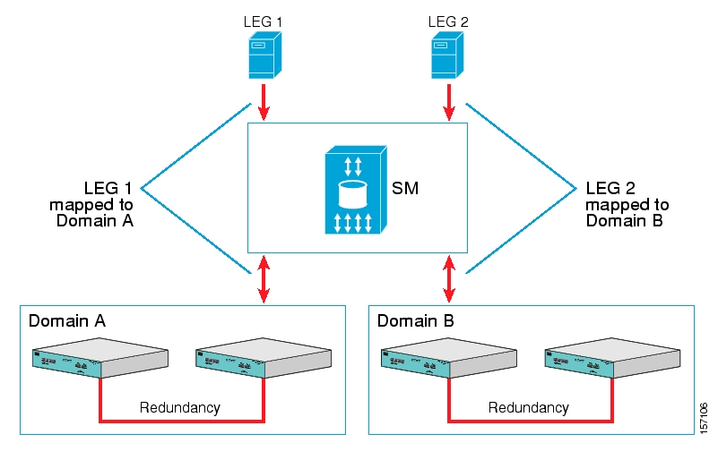
Note
Ensure that everything is properly installed before proceeding with configuring the SM.
To configure the SM using this scenario:
Edit the SM configuration file (
p3sm.cfg) to add the SCE devices to the SCE device repository and group the SCE devices to domains, as depicted in the above figure.Edit the SM configuration file, as displayed in the table below.
Reload the SM configuration file using the p3sm CLU.
Import the cable modems to the SM database using the p3cable CLU.
This scenario does not need an SCE platform configuration.
Table 4.1. Configuration File Parameters for Automatic Integration with Push Mode in a Cable Environment
|
Section and Parameter |
Value and Description |
|---|---|
|
SM General |
|
|
introduction_mode |
push |
|
High Availability Setup |
|
|
topology |
standalone The value should be set to |
|
Subscriber State Persistency |
|
|
save_subscriber_state |
true The value must be set to |
|
SCE_subscriber_persistency |
false The value should be set to |
|
SM-LEG Failure Handling |
|
|
timeout |
300 seconds (more tolerance may be advisable for SM-LEG failures in actual configurations) |
|
clear_all_mappings |
true The value should be set to |
|
LEG-Domain Association |
|
|
<LEG name> |
Define associations between LEGs and domains LEG-Domain associations should be defined in order that all subscriber mappings will be cleared on SM-LEG disconnection. If no association is defined, subscriber mappings will not be cleared (the |
|
Default Domains Configuration |
|
|
property |
None Configure the policy here if all domains in the system have the same policy. |
|
Domain.XXX |
|
|
aliases |
Define aliases, to facilitate working in cable environment Define aliases if working with LEGs that are not aware of system domains. Alternatively, you can define domains with names that match values produced by LEGs. |
|
property |
None Configure the policy here only if you want it to be applied to all subscribers in the domain. |
|
allow_dynamic_CM |
no The value should be set to |
|
Auto Logout |
|
|
auto_logout_interval |
60 minutes Auto-logout should be activated assuming that the AAA system cannot provide logout events, which is true in cable environments. The value defined here should be smaller than the CPE lease time in this cable environment. |
|
grace_period |
10 seconds You should define a relatively high value to eliminate mistakes because of management network delays. |
|
max_rate |
100 logouts per second You should define a value similar to the max-login rate to the SM. |
This scenario assumes the following:
Manual introduction of subscribers
Pull mode
Application that does not require preserving state
Note
Ensure everything is properly installed before proceeding with configuring the SM.
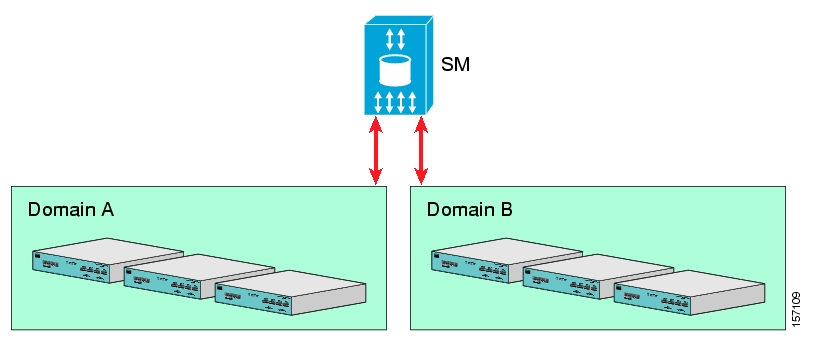
To configure the SM using this scenario:
Edit the SM configuration file (
p3sm.cfg) to add the SCE devices to the SCE device repository and group them to domains, as depicted in the above figure.Further edit the SM configuration file, as shown in the table below.
Reload the SM configuration file using the p3sm CLU.
Import the subscribers using the p3subsdb CLU (required for manual integration; there is no other way to bring subscribers into the SM).
Use the SCE platform CLI to configure the system for Pull mode:
Subscriber templates—In accordance with application
Anonymous groups—In accordance with your network and subscribers
Introduced subscriber aging—In accordance with your network and IP address allocation scheme
Table 4.2. Configuration File Parameters for Manual Integration with Pull Mode
|
Section and Parameter |
Value |
|---|---|
|
SM General |
|
|
introduction_mode |
pull |
|
High Availability Setup |
|
|
Topology |
standalone The value should be set to |
|
Subscriber State Persistency |
|
|
save_subscriber_state |
false |
|
SCE_subscriber_persistency |
false Defines whether the SCE stores subscriber information in persistent memory. Use this option only when there are just a few subscribers, which rarely change, in the system. |
|
SM-LEG Failure Handling |
|
|
Timeout |
Not applicable—No LEGs are involved in the scenario (use default—60 seconds) |
|
clear_all_mappings |
Not applicable—No LEGs are involved in the scenario (use default—no action) |
|
LEG-Domain Association |
|
|
<LEG name> |
Not applicable—No LEGs are involved in the scenario (Use default—no mappings) |
|
Default Domains Configuration |
|
|
Default policy (property.XXX) |
None Configure the policy here only if all domains in the system have the same policy. |
|
Domain.XXX |
|
|
Aliases |
Not applicable (use default—none) |
|
property.XXX |
None Configure the policy here only if you want to apply it to all subscribers in the domain. |
|
allow_dynamic_CM |
Not applicable—valid for cable environment only (use default – no) |
|
Auto Logout |
|
|
auto_logout_interval |
Not applicable (use default—0) |
|
grace_period |
Not applicable (use default—10) |
|
max_rate |
Not applicable (use default—50) |
When using a set-up with SM fail-over (based on two SM nodes connected in a cluster), the configuration is identical to the regular configuration, with one exception:
The topology parameter in the SM High Availability Setup Section should be set to cluster for both SM machines.
Other than that, SM fail-over configuration is performed normally via the p3sm.cfg configuration file. Manually copy the configuration file from the active SM to the standby SM.
For additional information of how to configure the VCS, see Appendix E, Veritas Cluster Server Requirements and Configuration.
This section introduces the Command-Line Utilities (CLU), and describes how to use the CLU for viewing, subscriber management, and other tasks when working with the SM.
Note
Some of the CLU operations and options can be specified by abbreviations. For this and additional information about the CLU, see Appendix B, Command Line Utilities.
This section contains the following subsections:
The procedures explained below invoke the following CLU commands:
p3batch
p3cable
p3clu
p3cluster
p3db
p3domains
p3inst
p3log
p3net
p3radius
p3rpc
p3sm
p3subs
p3subsdb
All CLU commands support the following operations for informative output:
|
Operation |
Description |
|---|---|
|
--help |
Prints the help for the specified CLU command, then exits. |
|
--version |
Prints the SM program version number, then exits. |
Place in quotation marks a command operation or option containing any of the following characters:
A space character
A separation sign (comma “,”; ampersand “&”; colon “:”)
An escape character (backslash “\”)
A command operation or option that contains any of the following characters must have that character preceded by an escape character:
An equal sign (=)
A quotation mark (“ or ”)
An escape character (backslash “\”)
Following are several examples of the above rules:
|
Operation/option contains the character |
Example of how operation/option should be written |
|---|---|
|
Space character |
--property=“file name” |
|
Escape character (backslash “\”) |
--property=“good\\bad” |
|
Equal sign (=) |
--property=“x\=y” |
|
Quotation marks (“ or ”) |
--name=“\“myQuotedName\”” (in the above example, inner quotation marks are escaped) |
|
Separation characters |
|
|
--names=“x,y” |
|
--names=“x&y” |
|
--names=“myHost:myDomain” |
One-letter abbreviations are available for some of the operations and options. For example, “-d” is an abbreviation for “--domain”. Note that only one hyphen (-), not two, precedes the letter for an abbreviation, and that if the operation or option takes a parameter, there is a space and not an equal sign before the parameter.
|
--domain=subscribers |
|
-d subscribers |
The abbreviations are useful if you want to specify an expression to be expanded by the UNIX shell, for example:
|
~pcube will be expanded by the UNIX shell |
Use the p3sm utility to configure the SM by reloading the SM configuration file p3sm.cfg. Use any standard text editor to edit the configuration file.
To reload the SM configuration:
From the shell prompt, type the following command:
p3sm -–load-config [--ignore-warnings] [--remote=OTHER_SM_IP[:port]]The configuration file is loaded, and the SM configuration updated accordingly.
The
––remoteoption loads the configuration first to the local SM, and afterward to the remote SM (in High Availability setups).
Use the p3sm utility to manage the SM on an ongoing basis. The p3sm utility enables you to start, stop, and resynchronize the SM.
To manage the SM:
From the shell prompt, enter a command using the following general format:
p3smoperation [--ne-name=SCE NAME]
The following table lists the p3sm operations relevant to managing the SM.
Table 4.3. p3sm Management Operations
|
Operation |
Description |
|---|---|
|
--show |
Displays the current SM configuration. |
|
--resync |
Resynchronizes the subscribers of the specified SCE with the SM database. The SCE is specified using the format |
|
--resync-all |
Resynchronizes the subscribers of all SCEs with the SM database. |
|
--start [--wait] |
Starts the server. The option |
|
--stop |
Stops the server. Note: When using fail-over, a simple shut-down of the SM does not work; the Veritas Cluster Server identifies that the SM is down and attempts to restart it. The correct procedure is: 1. Perform the manual fail-over. See Subscriber Manager (SM) Fail-Over. 2. Use the Veritas Cluster Manager Application to stop the monitoring (probing) of the SM. 3. Use the SM CLU ( |
|
--restart [--wait] |
Stops the server operation and then restarts it. The option |
|
--sm-version |
Displays the version of the currently installed SM. |
|
--sm-status [--detail] |
Displays the SM operational status: whether the SM is running or not and whether it is active or standby. If errors have occurred, a summary is displayed. To receive a detailed description, use the option |
|
--reset-sm-status |
Clears the errors displayed, enabling the user to see if new errors have occurred. |
|
--extract-support-file |
Retrieves the support file from the agent. This command extracts the SM support information to a defined file. The SM support information should be extracted and sent to Cisco Customer Support with each support request. |
|
--output |
Defines the name of the file to which the SM support information is extracted. |
|
--show-stats |
Displays statistics information regarding logon operations. The rate results are updated once every 10 seconds. |
|
--reset-stats |
Resets the statistics information. |
|
--logging=[on/off] |
Enables or disables the logging of user logon to the user log. Note: Enabling this flag may affect performance. |
Example 1:
The following example shows how to stop the server operation and then restart it.
p3sm -–restartExample 2:
The following example shows how to resynchronize an SCE whose logical name is SCE_1000A.
p3sm -–resync --ne-name=SCE_1000A
Example 3:
The following example shows how to extract the SM support information to a file named support.zip.
p3sm –-extract-support-file --output=support.zip
Use the p3subs utility to manage subscribers. You can add or remove subscribers. You can also manage subscriber properties and mappings with this utility.
To manage subscribers:
From the shell prompt, enter a command using the following general format:
p3subsoperation--subscriber=Subscriber-Name[--ip=IP-address] [--vlan-id=VLAN] [--mpls-vpn=VPN-ID@PE-IP] [--property=property-name=value] [--domain=domain-name] [--overwrite]
The subscriber on whom the operation is to be performed is specified by using the format
--subscriber=subscriber-name. A mapping (IP address, VLAN, or MPLS/VPN specification), property, or domain, if specified, uses the format displayed.
Note
If a domain is not specified, the subscriber is added to the default subscribers domain.
This section describes the following:
The following table lists the p3subs operations relevant to managing subscribers.
Table 4.4. p3subs Subscriber Operations
|
Operation |
Description |
|---|---|
|
--add |
Adds a subscriber or replaces the existing subscriber configuration. |
|
--set |
Updates mappings and/or properties for the specified subscriber. If the subscriber does not exist, this operation acts like the add operation. |
|
--remove |
Removes the specified subscriber. |
|
--show |
Displays information for the specified subscriber. |
Example 1:
The following example shows how to add a subscriber with the specified IP address.
p3subs --add --subscriber=jerry --ip=96.142.12.7Example 2:
The following example shows how to overwrite subscriber information. Because the subscriber named “jerry” already exists, the add operation would fail; however, the overwrite option allows the IP address to be overwritten.
p3subs --add --subscriber=jerry --ip=96.128.128.42 --overwrite
The following table lists all the p3subs operations relevant to managing mappings.
Table 4.5. p3subs Mapping Operations
|
Operation |
Description |
|---|---|
|
--set |
Adds or updates a subscriber. If the mappings exist, it replaces the existing mappings, unless the additive-mapping option is used. |
|
--remove-all-mappings |
Removes all the mappings of the specified subscriber. |
|
--remove-mappings |
Removes specified mappings of the specified subscriber. |
|
--show-all-mappings |
Displays all the mappings for the specified subscriber. |
Table 4.6. p3subs Mapping Options
|
Option |
Description |
|---|---|
|
--additive-mapping |
Adds the specified mappings to the existing ones (instead of replacing the existing mappings when this option is not used). Used with the set operation. |
Example:
The following example shows how to removes all the mappings for a specified subscriber.
p3subs --remove-all-mappings --subscriber=jerry You can specify the following mapping types for each subscriber:
IP address or range—Use the
--ip-addressoption. For an IP address, use the dotted notation. A range is used to specify several consecutive mappings, for example, the notation 1.1.1.0/30 is used to specify the IP addresses 1.1.1.0 to 1.1.1.3. You can specify multiple mappings by using a comma.VLAN—Use the
--vlan-idoption. An integer number specifies the VLAN. You can specify multiple mappings by using a comma.MPLS/VPN—Use the
--mpls-vpnoption. The notation of the MPLS/VPN mappings isVPN-ID@PE-IP. VPN-ID is the VPN identifier of the VPN site (it can be RT or RD). The PE-IP is the loopback IP address of the PE router attached to the VPN. For more information on the MPLS/VPN mappings, see the Cisco SCMS SM MPLS/VPN BGP LEG Reference Guide.
Note
You cannot specify different types of mappings for the same subscriber.
Note
When working with VLAN mapping types, the SCE must be configured using the following CLI:
SCE2000#> configure
SCE2000(config)#> in li 0
SCE2000(config if)#> VLAN symmetric classify
The following table lists the p3subs operations relevant to managing subscriber properties. The property names depend on the application running on your system. To find descriptions of the application property names and values, see the documentation provided with the application installed on your system.
Table 4.7. p3subs Subscriber Property Operations
|
Operation |
Description |
|---|---|
|
--set |
When specifying a property, the subscriber record is updated with the specified property and value. |
|
--reset-property |
Resets specified property of specified subscriber to its default value. |
|
--show-property |
Displays value of specified property of specified subscriber. |
|
--show-all-properties |
Displays all the properties of the specified subscriber. |
|
--show-all-property-names |
Displays all the property names and descriptions. |
|
--remove-properties |
Removes specified properties or custom properties from the specified subscriber record. |
Example:
The following example shows how to set a property value for a specified subscriber.
p3subs --set --property=packageId=1 --subscriber=jerryThe following table presents the p3subs operation that clears a subscriber’s applicative state.
Table 4.8. p3subs Mapping Operations
|
Operation |
Description |
|---|---|
|
--clear-state |
Clears the subscriber’s applicative state. This command clears only the backup copy at the SM. It does not clear the applicative state record in the SCE platform. |
Example:
The following example shows how to clear the applicative state of the specified subscriber. Note that this command clears only the backup copy at the SM. It does not clear the applicative state record in the SCE platform.
p3subs –-clear-state --subscriber=jerryUse the p3subsdb utility to manage the SM database. You can import subscriber information for a group of subscribers from a CSV file into the SM database. You can also export subscriber information from the SM database to a CSV file.
Note
The format of the CSV file depends on the application. The documentation of a specific application specifies the CSV file format for that application.
To manage the SM database:
From the shell prompt, enter a command using the following general format:
p3subsdboperation[--domain=domain-name] [filename]
The following table lists the p3subsdb operations.
Table 4.9. p3subsdb Operations
|
Operation |
Description |
|---|---|
|
--clear-all |
Removes all subscriber records from the database. |
|
--clear-domain |
Removes all subscriber records from the specified domain. |
|
--show-num |
Displays the number of subscribers in the database for the specified domain. |
|
--show-all |
Lists all subscriber names. |
|
--show-domain |
Lists all subscriber names in the specified domain. |
|
--import |
Imports subscribers to the database from a specified CSV file. The filename that is to be imported is specified using the format
|
|
--export |
Exports subscribers from the database to a specified CSV file. The filename that is to be exported is specified using the format
|
|
--remove |
Removes subscribers from the database using a specified CSV file. The filename is specified using the format |
|
--clear-all-states |
Clears the state of all subscribers in the SM database. |
|
--remove-property |
Removes a specified property from all subscribers in the system. Note: After running this command, you should re-synchronize all SCE devices. |
|
--remove-all-ip |
Removes all the IP addresses of all subscribers. |
|
--remove-all-vlan |
Removes all the VLAN tags of all subscribers. |
|
--remove-all-mpls-vpn |
Removes all the MPLS/VPN mappings of all subscribers. |
Table 4.10. p3subsdb Options
|
Operation |
Description |
|---|---|
|
--domain=DOMAIN |
Performs the operation on the specified DOMAIN. If DOMAIN is none, then the operation refers to the subscribers who have no domain specified. |
|
--prefix=NAME |
Used in the export command for filtered export. |
|
--property=PROPERTY |
Used in conjunction with the |
Table 4.11. p3subsdb File Options
|
Operation |
Description |
|---|---|
|
--file=FILE |
One or more subscriber CSV FILEs to import from. |
|
--output=FILE |
Subscriber CSV FILE to export to. |
Example 1:
The following example shows how to list all subscribers in a specified domain.
p3subsdb --show-domain --domain=mainDomainExample 2:
The following example shows how to import subscribers from the specified CSV file.
p3subsdb --import --file=goldSubscriberFile.csv
Example 3:
The following example shows how to export subscribers with filtering options to a specified CSV file.
p3subsdb --export --prefix=a -–output=silverSubscriberFile.csv
Use the p3net utility for viewing the connection status of network elements and trying to reconnect disconnected elements.
To view the connection status of a network element or to reconnect a disconnected element:
From the shell prompt, enter a command using the following general format:
p3netoperation--ne-name=logical-name
The following tables list p3net operations and options.
Table 4.12. p3net Operations
|
Operation |
Description |
|---|---|
|
--show-all |
Shows all the configured network elements. |
|
--show |
Shows an element's connection status. |
|
--connect |
Tries to connect a disconnected element |
Table 4.13. p3net Options
|
Network Element Option |
Description |
|---|---|
|
--ne-name=NAME |
Specifies the logical NAME for the network element. |
|
--detail |
(Optional) Used with the --show-all operation for displaying additional information as a table. |
Example:
The following example shows how to display a network element's connection status.
p3net --show -–ne-name=mainNEUse the p3domains utility for viewing the subscriber domains. As explained in Introducing the Subscriber Manager, subscriber domains are groups of SCE devices that serve the same subscribers.
To view subscriber domains:
From the shell prompt, enter a command using the following general format:
p3domainsoperation--domain=domain-name
The following tables list p3domains operations and options.
Table 4.14. p3domains Operations
|
Operation |
Description |
|---|---|
|
--show-all |
Shows all configured domains. |
|
--show |
Shows a domain and its associated network elements. |
Table 4.15. p3domain Options
|
Domain/NE Option |
Description |
Notes |
|---|---|---|
|
--domain=DOMAIN |
DOMAIN specifies logical name |
“none” cannot be used, it is a reserved word |
In the cable environment, the SM supports two modes of operation: CM as Subscriber and CPE as Subscriber, as described in CPE as Subscriber in Cable Environment.
This section only discusses the support of the CPE as Subscriber mode. In this mode, the CPE is modeled as the subscriber, and it inherits its policy and domain from the cable modem (CM) through which it connects to the network. Each cable modem is linked with one or more CPEs. (For background information about special characteristics of the CPE as Subscriber mode in the cable environment, see CPE as Subscriber in Cable Environment.)
Use the p3cable utility commands to import cable modem information from a CSV file to the SM, and to export the cable modem information from the SM to a CSV file. You can also use this utility to clear the repository of all cable modems, and to show whether to allow or deny the login of CPEs that belong to unfamiliar cable modems; i.e., cable modems that do not exist in the SM database. However, for specifying whether to allow or deny such a login, use the Cable Adapter section of the p3sm.cfg configuration file.
To manage the cable modems:
From the shell prompt, enter a command using the following general format:
p3cableoperation--cm=CM-name
The following table lists the p3cable operations.
Table 4.16. p3cable Operations
|
Operation |
Description |
|---|---|
|
--import-cm |
Imports cable modems from a CSV file. The filename that is to be imported is specified using the format The results go to a results file. |
|
--export-cm |
Exports cable modems to a CSV file. The filename that is to be exported is specified using the format The results go to a results file. |
|
--clear-all-cm |
Clears the repository of all cable modems. |
|
--show-dynamic-mode |
Shows whether to allow or deny the login of CPEs that belong to unfamiliar cable modems; i.e., cable modems that do not exist in the SM database. |
Example 1:
The following example shows how to import cable modems from a CSV file.
p3cable -–import-cm --file=CMFile.csvExample 2:
The following example shows how to clear the repository of all cable modems:
p3cable --clear-all-cmExample 3:
The following example shows how to display login status (allow/deny) of CPEs that belong to cable modems that do not exist in the SM database:
p3cable --show-dynamic-modeUse the p3inst utility to install or uninstall an application (pqi file). You can install an application on the SM to customize the components. You can also upgrade an existing application to a new version, or uninstall a previously installed application.
To install or uninstall an application:
From the shell prompt, enter a command using the following general format:
p3instoperation [file options] [installation/upgrade parameters]
The following table lists the p3inst operations.
Table 4.17. p3inst Operations
|
Operation |
Description |
|---|---|
|
--install |
Installs the specified application pqi file to the SM. It may be necessary to specify arguments for the installation procedure in the command line. |
|
--uninstall |
Uninstalls the specified application pqi file from the SM. |
|
--upgrade |
Upgrades an existing application using the specified application pqi file. It may be necessary to specify arguments for the upgrade procedure in the command line. |
|
--rollback |
Returns the specified application to the previous version. Rollback is the reverse of an upgrade operation: it reverses the upgrade. |
|
--describe |
Displays the contents of the specified application pqi file. |
|
--show-last |
Lists the details of the last installed application pqi file |
Example 1:
The following example shows how to install the specified installation file.
p3inst --install --file=myInstallation.pqiExample 2:
The following example shows how to uninstall the specified installation file.
p3inst --uninstall –-file=oldInstallation.pqi
Cisco provides a proprietary RPC (Remote Procedure Call) interface to the SM. Use the p3rpc utility to view the configuration and statistics of the PRPC server.
To display PRPC interface server information:
From the shell prompt, enter a command using the following general format:
p3rpcoperation
The following table lists the p3rpc operations.
Table 4.18. p3rpc Operations
|
Operation |
Description |
|---|---|
|
--show |
Displays the port number the PRPC server listens to, the maximum number of connections, the current number of active connections, and the host IP. |
|
--show-statistics |
Displays the PRPC server statistics. They contain information about the number of current PRPC sessions and statistics for PRPC server actions such as invocations and errors. |
|
--reset-statistics |
Clears the PRPC server statistics. |
|
--show-client-names |
Displays the names of the connected clients. |
Example:
The following example displays the statistics of the PRPC server.
p3rpc –-show-statisticsUse the p3cluster utility to view the redundancy state of the SM and its components. This utility also supports operations that alter the redundancy state of the SM. These operations are used by the SM Cluster Agent and for administrative tasks.
To manage the cluster:
From the shell prompt, enter a command using the following general format:
p3clusteroperation
The following table lists the p3cluster operations.
Table 4.19. p3cluster Operations
|
Operation |
Description |
|---|---|
|
--show |
Displays the redundancy status of the SM and its components. |
|
--active |
Make the SM become the active SM in the cluster. |
|
--standby |
Make the SM become the standby SM in the cluster. |
Example:
The following example displays the redundancy status of the SM and it components.
p3cluster –-showUse the p3log utility to configure and manage the user log. All user-related events and errors are directed to the SM user log. You can extract the contents of the user log to a specified file in order to read and save its contents. You can also clear the user log.
Use the p3radius utility to view the statistics of the RADIUS Listener LEG. For information about this CLU, see the Cisco SCMS SM RADIUS Listener LEG Reference Guide.
This section describes the following:
Running a batch file (p3batch)
Printing general help about CLU commands (p3clu)
Database operations (p3db)
Use the p3batch utility to run a batch file and execute its commands. Using any text editor, you can create a batch file that contains a series of CLU commands, one command per line. This operation (p3batch) enables you to run multiple operations on a single connection to the SM.
To run a batch file:
From the shell prompt, enter a command using the following general format:
p3batch[file-options] [error-options]
Table 4.20. p3batch File Option
|
Operation |
Description |
|---|---|
|
--file=FILE |
Runs a batch file, where FILE specifies the CLU script (batch) file to run. |
Table 4.21. p3batch Error Option
|
Error Option |
Description |
|---|---|
|
--skip-errors |
Specifies that the batch operation should not halt if an error occurs. If this flag is not used, the batch operation will halt if an error occurs. |
Example 1:
The following example shows how to run a batch file that will halt if an error occurs.
p3batch --file=mainBatchFile.txtExample 2:
The following example shows how to run a batch file that will not halt if an error occurs.
p3batch --file=mainBatchFile.txt --skip-errorsUse the p3clu utility to print a list of all supported CLU utilities and operations.
Use the p3db utility to manage and monitor the TimesTen database. The CLU exposes capabilities of the some of TimesTen CLUs with respect to specific needs of the SM.
To manage or monitor the TimesTen database:
From the shell prompt, enter a command using the following general format:
p3dboperation [options]
The following tables list the p3db operations and options.
Note
Use caution when activating commands that can affect the database. If used incorrectly, these commands may possibly damage the database.
Table 4.22. p3db Operations
|
Operation |
Description |
|---|---|
|
--status |
Displays the database status. |
|
--destroy-rep-db |
Destroys the replicated data-store. |
|
--destroy-local-db |
Destroys the local data-store. |
|
--keep-in-mem [SECS] |
Indicates to the database daemon how many seconds to keep the database in the memory, after the last connection to the database is down. Use this option in large databases to reduce the SM restart time. Note: To prevent limitations in performing database destroy, do not use values above a few minutes (that is, above a few hundred seconds). |
|
--rep-status |
Displays status of the replication agent. |
|
--rep-start |
Starts the replication agent. Note: Use only for database recovery. |
|
--rep-stop |
Stops the replication agent. Note: Use only for database recovery. |
|
--duplicate |
Copies the data-store from the remote machine (specified by "--remote=REMOTE_HOSTNAME") to the local machine (specified by "--local=LOCAL_HOSTNAME"). Note: This option is applicable only for a cluster setup. For additional information, see Data Duplication Procedure. |
|
--set-rep-scheme |
Sets the database scheme to be replicated to the remote machine. Note: This option is applicable only for a cluster setup. |
|
--drop-rep-scheme |
Removes the database scheme that the remote machine uses for replication. Note: This option is applicable only for a cluster setup. |
Example
The following example shows how to request the status of the replication agent, and also lists a typical response:
bash-2.03$ p3db --rep-status
Peer name         Host name                 Port    State  Proto
----------------  ------------------------ ------  ------- -----
PCUBE_SM_REPOSITORY  SM_REP1          Auto   Start      11

Last Msg Sent Last Msg Recv Latency TPS     RecordsPS Logs
------------- ------------- ------- ------- --------- ----
00:00:02      00:00:00         1.15    2723      5447    1

the subscriber DB is ok
Command terminated successfullyThis appendix describes in detail all the parameters that can be configured by using the Subscriber Manager (SM) configuration file. The shorter description of SM configuration given in Configuration and Management is more oriented toward the routine configuration tasks that can be performed online using the CLU.
The SM can be configured only by using its configuration file (the CLU is used for displaying, not configuring). The SM has one configuration file, p3sm.cfg, which is located under ~pcube/sm/server/root/config/p3sm.cfg. To change any configuration parameter, edit the configuration file using a standard text editor, and then use the CLU to reload it (see Reloading the SM Configuration (p3sm)).
You can use the p3sm.cfg configuration file for setting parameters for the following:
SM configuration
Radius Listener configuration
Redundancy (cluster/standalone) configuration
Domain configuration
SCE configuration
Cable adapter configuration
PRPC port configuration
FTP port configuration
HTTP port configuration
Database configuration
The following sections correspond to the sections of the SM configuration file, p3sm.cfg.
For an explanation of the terms and concepts used in these sections, see Configuring a Subscriber Management Solution.
The [SM General] section contains the following parameters:
introduction_modeDefines whether the SM introduces the subscribers to the SCE devices immediately after a login operation (Push mode), or only when the SCE requests the subscriber specifically (Pull mode).
Possible values for this parameter are
pushandpull. The default value ispush.The following is an example of assigning a value to this parameter:
introduction_mode=pushapplication_subscriber_lockDefines whether to lock subscriber-related operations (login, logout, etc.) at the application level. Set this flag to
trueonly if several LEG applications can update simultaneously the same parameters of a subscriber.Possible values for this parameter are
trueandfalse. The default value istrue.The following is an example of assigning a value to this parameter:
application_subscriber_lock=true
force_subscriber_on_one_sceDefines whether the SM supports the solution when a Cisco 7600/6500 Router is used for load-balancing among several SCE platforms. In this solution when one SCE platform fails, subscriber traffic is redistributed to a different SCE platform. The SM must remove subscribers from the failed SCE platform and send the relevant subscriber information to the new SCE platform. This parameter is relevant only in the pull introduction mode.
Possible values for this parameter are
trueandfalse. The default value isfalse.
Note
Changing this value requires a restart of the SM process.
The following is an example of assigning a value to this parameter:
force_subscriber_on_one_sce=false
logon_logging_enabled
Defines whether to enable the logging of subscriber logon events.
Note
Setting this flag to true might cause performance degradation.
Possible values for this parameter are true and false. The default value is false.
The following is an example of assigning a value to this parameter:
logon_logging_enabled=false
subscriber_id_case_sensitivityOptional parameter that defines whether subscriber IDs are case sensitive or not. When this flag is set to
no, all subscriber IDs in the subscriber database are set to be lower case. For example, 'JohnSmith' is converted to 'johnsmith'.
Note
Setting this flag to no when the subscriber database is not empty is not allowed. An error message will be shown and the configuration will not be loaded. To overcome this limitation, you can do the following:
1. Export the subscriber database to an external file
2. Clear the subscriber database
3. Change the configuration by setting the flag to no and load the new configuration
4. Import the subscriber database from the external file
Possible values for this parameter are yes and no. The default value is yes.
The following is an example of assigning a value to this parameter:
subscriber_id_case_sensitivity=yes
The [SM High Availability Setup] section contains the following parameter:
topologyDefines in what kind of topology the SM should work.
Possible values for this parameter are
standaloneandcluster. The default value isstandalone.The following is an example of assigning a value to this parameter:
topology=standalone
The [Subscriber State Persistency] section contains the following parameters:
SCE_subscriber_persistency
Defines whether the SCE stores subscriber information in persistent memory. Use this option only when there are just a few subscribers, which rarely change, in the system.
Note
Setting this parameter to true causes performance degradation, reducing the rate of subscriber updates.
Possible values for this parameter are true and false. The default value is false.
The following is an example of assigning a value to this parameter:
SCE_subscriber_persistency=false
The [SM-LEG Failure Handling] section contains parameters that affect the discovery of an SM-LEG connection failure event and the actions taken by SM upon a connection failure event. A network problem or a severe failure (such as reboot) of the SM or the LEG can cause an SM-LEG connection failure event.
The [SM-LEG Failure Handling] section contains the following parameters:
clear_all_mappingsDefines the behavior of the SM in case of LEG-SM connection failure. This parameter is relevant only for cases where the SM and LEG are running on different machines.
Note
This parameter defines a behavior that is similar for all LEG applications connected to the SM.
If this parameter is set to true and a SM-LEG connection failure occurs that is not recovered within the defined timeout, the mappings of all subscribers in the domains defined in the [LEG-Domains Association] section for the LEG that was disconnected will be removed.
Note
Important: If you set the clear_all_mappings parameter to true, you must also set the LEGDomains Association parameter to clear the mappings in the SM if an SM-LEG connection failure occurs.
Possible values for this parameter are true and false. The default value is false.
The following is an example of assigning a value to this parameter:
clear_all_mappings=false
timeoutDefines the time in seconds from a SM-LEG connection failure until clearing the mappings in the SM database.
Note
It takes several seconds for the SM to detect an SM–LEG connection failure. You must add this time to the value of the timeout parameter when calculating how long it will take the SM to react in case of an SM–LEG connection failure. For example, if timeout is set to 80, it will take 80 seconds from the failure detection time until the SM clears the subscribers database.
The default value for this parameter is 60 (seconds).
The following is an example of assigning a value to this parameter:
timeout=60
The [LEG Domains Association] section defines the domains for which the mapping of all subscribers that belong to them will be cleared on SM-LEG connection failure. This section is relevant only if the clear_all_mappings parameter has been set in the [SM-LEG Failure Handling] section.
Note
Even though you set the LEGDomains Association parameter, you must also set the clear_all_mappings parameter to true to actually clear the mappings in the SM if an SMLEG connection failure occurs.
This section contains a list of LEG-Domain associations, each item in a separate line. Each LEG-Domain association is specified as shown for the following parameter:
<LEG name>=domain_name1[,domain_name2,...]Defines the domains whose subscriber mapping will be cleared on an SM-LEG connection failure. The key is the
<LEG name>.To determine which value or values to use for the
<LEG name>key, consult the documentation of the LEG that you use. The<LEG name>usually is divided into two parts:<hostname>.<common suffix>. The first part is a general LEG identifier. The second part is extracted from the machine on which the LEG is running. Alternatively, you can use the CLU commandp3rpc --show-client-names.A
<LEG name>of “*” specifies all LEGs. The (comma-separated) values are the domains (domain_name) to be cleared in the event of a network link failure (connection failure) between the specified LEG and the SM. A value of “*” for thedomain_namespecifies all subscriber domains in the system.
Note
The LEG name is case sensitive.
By default, there are no LEG domain mappings.
The following is an example of assigning values to this parameter:
10.1.12.76.NB.SM-API.J=home_users 10.1.12.77.B.SM-API.C=office_usersThe following is an example of specifying all subscriber domains:
10.1.12.31.CNR.LEG=*
The following is an example of specifying all LEGs and all subscriber domains:
*=*
Each [Domain.XXX] section specifies one domain, where XXX represents the domain name.
This section contains the following parameters:
elements=logical_name1[,logical_name2,...]Specifies the name or names of the SCE platforms that are part of the domain.
Note
Each name must be the exact "XXX" name (case sensitive) that appears in the SCE.XXX Section.
Following is an example of assigning a value to this parameter:
elements=se0,se1
aliases=alias_name1[,alias_name2,...]
Defines domain aliases. When subscriber information is received from the LEG with one of the aliases (for example, alias1), the information is distributed to the domain that matches this alias (for example, domain_name1). A typical alias could be a network access device IP address, where, for example, each string in the values can be the IP address of a NAS or a CMTS.
Note
Each alias can appear in only one domain section.
By default, there are no domain aliases.
The following is an example of assigning a value to this parameter:
aliases=10.10.88.99,10.10.88.98
property.name1=value1[,property.name2=value2,...]Defines the default policy properties values for a domain. Unless the LEG/API overrides these defaults when it logs in the subscriber to the SM, the subscriber policy is set according to the default policy properties values of its domain.
The policy format is a comma-separated list of
property_name=property_value, where each property value is an integer.
Note
To learn more about policy specification, see the Service Control Application for Broadband (SCA BB) User Guide.
The following is an example of assigning a value to this parameter:
property.packageId=1
The [Default Domains Configuration] section defines default policy for the domain. It is used for those domain properties that were not defined in the domain policy configuration (see [Domain.XXX]), and for properties of domains for which no policy whatsoever was defined.
This section contains the following parameter:
property.name1=value1[,property.name2=value2,...]Defines the default policy properties values for all domains. Unless the LEG/API overrides these defaults when it logs in the subscriber to the SM, or unless they are overwritten by the default policy property values of the subscriber domain, the subscriber policy is set according to the global default policy property values defined in this section.
The policy format is a comma-separated list of
property_name=property_value.
Note
To learn more about policy specification, see the Cisco Service Control Application for Broadband (SCA BB) User Guide.
The following is an example of assigning a value to this parameter:
property.packageId=1
The [Auto Logout] section defines the parameters for the Auto Logout feature, which is relevant mainly for cable environments. This feature is relevant to automatic integrations where the LEG/API cannot provide logout indications. In such a case, you can turn on the automatic logout mechanism, which instructs the SM to log out a subscriber automatically after a certain period of time. Note that a login event for a subscriber resets the subscriber logout timer.
Note
Not using the Auto Logout feature in the scenario described above (a provisioning system that can provide subscriber login events to the SM but cannot provide subscriber logout events) might result in exhausting the SCE resources, because subscribers are logged in but are never logged out.
This section contains the following parameters:
auto_logout_intervalConfigures the interval value, in seconds, of the SM auto-logout mechanism. Every interval, the SM checks for which subscriber IP addresses the lease time has expired, and begins to automatically remove these IP addresses from the system.
Lease time is the timeout defined by the LEG during the login operation per each IP address. All subscriber login events will start a timer of lease-time seconds. When the timer expires and the grace period (see below) has also expired, the subscriber IP addresses are removed, causing the subscriber to be removed from the SCE platform database. Any login event by the subscriber with an existing IP address during the timer countdown period resets the timer, causing it to restart.
Setting the interval value to zero (0) disables the SM auto-logout mechanism.
Setting the interval to a value greater than zero enables the SM auto-logout mechanism.
Note
The interval should be smaller, but of the order of the lease time used in the system. It is recommended that during a lease time the auto-logout task will run several times.
The default value for this parameter is 0 (seconds), meaning the auto-logout mechanism is disabled.
The following is an example of assigning a value to this parameter:
auto_logout_interval=600
The following is an example of deactivating the Auto Logout feature:
auto_logout_interval=0
grace_periodDefines the grace period, in seconds, for each subscriber. After a subscriber auto-logout timeout has expired, the subscriber IP address is logged out automatically after the grace period has also expired.
The default value for this parameter is 10 (seconds).
The following is an example of assigning a value to this parameter:
grace_period=10
max_rateDefines the maximum rate (logouts per second) that the auto-logout task is allowed to perform logouts from the system. This limit spreads out the load of the logout operations over time, reducing the performance impact on other operations.
Calculate the value for this parameter to spread the logouts over at least half of the auto_logout_interval time. The default value is 50.
The following is an example of assigning a value to this parameter:
max_rate=50
Note
Use the lowest rate possible to reduce the influence of the auto-logout process on other operations. However, as a guideline, calculate the value so that the auto-logout process takes about half of the auto_logout_interval and be similar to the maximum login rate to the SM.
Use the [Radius Listener] section for integrating with the RADIUS Listener LEG.
Note
For additional RADIUS Listener configuration information, see the Cisco SCMS SM RADIUS Listener LEG Reference Guide.
This section contains the following parameters:
startDefines whether the SM should run the RADIUS Listener at startup.
Possible values for this parameter are
yesandno. The default value isno.The following is an example of assigning a value to this parameter:
start=no
accounting_portDefines the RADIUS Listener's accounting port number.
The default value is 1813.
The following is an example of assigning a value to this parameter:
accounting_port=1813
ip(Optional) Defines the IP address to where the RADIUS Listener should bind. Use this parameter in cluster setups or when the machine local-host IP is not the IP to where the RADIUS messages are sent.
By default, this parameter is not set.
The following is an example of assigning a value to this parameter:
ip=192.56.21.200
Each [Radius.NAS.XXX] section specifies a single Network Access System (NAS), where XXX represents the NAS name.
Note
The RADIUS Listener LEG refers to all of its RADIUS clients as NAS devices, even though they might be RADIUS servers.
This section contains the following parameters:
domainSpecifies the Cisco Service Control subscriber domain name.
The following is an example of assigning a value to this parameter:
domain=my_domain
IP_addressSpecifies the IP address in dotted notation (xxx.xxx.xxx.xxx).
The following is an example of assigning a value to this parameter:
IP_address= 1.1.1.1
NAS_identifierSpecifies the name of the NAS that exists in the NAS-ID attribute. For information about the use of this parameter, see the Cisco SCMS SM RADIUS Listener LEG Reference Guide.
The following is an example of assigning a value to this parameter:
NAS_identifier=RedHat37
secretSpecifies a secret key defined in the NAS for this connection.
The following is an example of assigning a value to this parameter:
secret=mysecret
The [Radius.Property.Package] section defines the RADIUS attribute from which a subscriber package is retrieved.
Note
This section is commented out in the configuration file. If you want to retrieve a subscriber package from an attribute other than a RADIUS attribute, you should uncomment this section.
This section contains the following parameters:
radius_attributeSpecifies the RADIUS protocol attribute number. Use the value of
26for Vendor Specific Attributes (VSA). Use–1if you do not want to extract from any attribute.The following is an example of assigning a value to this parameter:
radius_attribute=26
radius_attribute_typeSpecifies the RADIUS attribute type.
Possible values for this parameter are
integerandstring. The default value isinteger.The following is an example of assigning a value to this parameter:
radius_attribute_type=integer
use_defaultDefines whether to use a default value if the attribute was not found.
Possible values for this parameter are
trueandfalse. The default value istrue.The following is an example of assigning a value to this parameter:
use_default=true
defaultDefines the default value to use if the attribute was not found.
There is no default value. (If this parameter is used, it should have non-empty value.)
The following is an example of assigning a value to this parameter:
default=0
Additional parameters for VSA association
Use the following additional parameters only if the association is based on Vendor Specific Attributes (VSA):
radius_attribute_vendor_id=<insert the vendor identifier number here>
radius_sub_attribute=<insert the attribute number here>
The [Radius.Subscriber ID] section defines the RADIUS attribute on which to base the subscriber ID association. Default association is based on the user name attribute.
Note
This section is commented out in the configuration file. If you want to base subscriber ID association on an attribute other than user name, you should uncomment this section.
This section contains the following parameters:
radius_attributeSpecifies the RADIUS protocol attribute number. Use the value of
26for Vendor Specific Attributes (VSA). Use the value of–1to use the default.The following is an example of assigning a value to this parameter:
radius_attribute=26radius_attribute_typeSpecifies the RADIUS attribute type.
Possible values for this parameter are
integerandstring. The default value isinteger.The following is an example of assigning a value to this parameter:
radius_attribute_type=string
Additional parameters for VSA association
Use the following additional parameters only when basing the association on Vendor Specific Attributes (VSA). For example, to use the 3GPP_IMSI attribute, set:
radius_attribute_vendor_id=10415
radius_sub_attribute=1
The [RPC.Server] section represents the PRPC server configuration.
This section contains the following parameters:
portDefines the PRPC server port. The default is 14374.
The following is an example of assigning a value to this parameter:
port=14374security_levelDefines whether the PRPC server forces authentication on all connections (
full), authenticates connections that support authentication while still accepting connections that do not (semi), or not to enforce authentication (none). When clients attempt to connect to the SM, they are authenticated if configured correctly.Possible values for this parameter are
full,semi, andnone.The default value is
semi.
Note
SCA BB Console 3.0.5 supports authentication with the SM PRPC Server; therefore, it can be used in conjunction with all security_level values.
Note
In version 3.0.5, the SM Java API, SM C/C++ API, and CNR LEG do not support authentication with the SM PRPC Server; therefore, if installed, the security level cannot be configured to full.
The following is an example of assigning a value to this parameter:
security_level=semi
The [MPLS-VPN] section contains configuration parameters that are relevant to MPLS/VPN installations. See the Cisco SCMS SM MPLS/VPN BGP LEG Reference Guide for a description of Subscriber Management in MPLS/VPN networks.
This section contains the following parameters:
vpn_idDefines the BGP attribute to use to identify the VPN subscribers.
Possible values for this parameter are
RDorRT. The default value isRT.The following is an example of assigning a value to this parameter:
vpn_id=RD
log_allDefines the logging level of the BGP LEG.
Possible values for this parameter are
trueorfalse. The default value isfalse. If set totruethe SM logs all BGP packets that were received by it and is useful during the integration and testing phase.The following is an example of assigning a value to this parameter:
log_all=false
Each [SCE.XXX] section represents a single SCE platform, where XXX represents the SCE logical name.
This section contains the following parameters:
ipDefines the IP address of the SCE device.
The following is an example of assigning a value to this parameter:
ip=11.12.13.1
portDefines the port through which to connect to the SCE platform. The default is 14374.
The following is an example of assigning a value to this parameter:
port=14374
The SM manages an internal FTP server for various purposes.
The [FTP] section contains the following parameters:
startDefines whether the SM should run the FTP server at startup.
Possible values are
yesandno. The default isno.The following is an example of assigning a value to this parameter:
start=yes
portDefines the FTP server port. The default is 21000.
The following is an example of assigning a value to this parameter:
port=21000
The following parameters define the TCP ports range when the FTP server works in passive mode:
#first_passive_port = 21001 #last_passive_port = 21100Note
Uncomment these parameters when working with the FTP server via a firewall.
The SM manages an internal HTTP adapter server that is a technician interface.
The [HTTP Tech-IF] section contains the following parameters:
startDefines whether the SM should run the HTTP server at startup.
Note
This is a technician interface and normally should not be used.
Possible values are yes and no. The default is no.
The following is an example of assigning a value to this parameter:
start=yesport
Defines the HTTP server port. The default is 8082.
The following is an example of assigning a value to this parameter:
port=8082
The SM manages an internal RDR server that is used to receive RDR messages from the SCE.
The [RDR Server] section contains the following parameters:
startDefines whether the SM should run the RDR server at startup.
Note
This interface should be used when installing the SCE-Sniffer LEGs on the SM.
Possible values are yes and no. The default is no.
The following is an example of assigning a value to this parameter:
start=yes
portDefines the RDR server port. The default is 33001.
The following is an example of assigning a value to this parameter:
port=33001
max_connectionsDefines the maximum number of connections accepted by the server. The default is 10.
The following is an example of assigning a value to this parameter:
max_connections=10
The SM manages a Cable Adapter, a special cable support module that is a translator between the cable world (DHCP events) and the SM. For additional information, see CPE as Subscriber in Cable Environment.
The [Cable Adapter] section contains the following parameter:
allow_dynamic_CMDefines whether to allow logins from cable modems (CM) that are not in the SM database.
Possible values are
yesandno. The default isno.The following is an example of assigning a value to this parameter:
allow_dynamic_CM=no
The [Data Repository] section defines the SM operation with the TimesTen In-Memory Database.
Note
Some of the parameters in this section are discarded on regular configuration loading, and resetting them requires restarting the SM.
The [Data Repository] section contains the following parameters:
support_ip_rangesDefines whether the SM supports IP-Ranges. Disabling this support provides better performance.
Note
Resetting this parameter requires restarting the SM. This parameter is discarded on regular configuration loading (using CLU).
Possible values are yes and no. The default is no.
The following is an example of assigning a value to this parameter:
support_ip_ranges=yes
checkpoint_interval_in_secondsDefines the interval, in seconds, for calling the TimesTen checkpoints. Reducing the value affects performance, increasing the value increases vulnerability to power-down.
The default value is 60 (seconds).
The following is an example of assigning a value to this parameter:
checkpoint_interval_in_seconds=60
max_range_sizeDetermines the maximum IP range size used in the system.
This parameter is used for improving performance of the SM in Pull mode when the Data Repository section is configured with
support_ip_ranges=yes.
Note
Defining this parameter with too low a value may cause incorrect operation in handling pull requests.
The default value is 256.
The following is an example of assigning a value to this parameter:
max_range_size=256
This appendix describes the Command-Line Utilities (CLU) that is distributed with the Subscriber Manager (SM) application.
The SM provides a set of Command-Line Utilities (CLU). The CLU is designed mainly for viewing SM operations and statistics, and subscriber management, therefore only subscriber-related CLU changes are persistent. The CLU is used for configuration only indirectly, in that it loads the edited configuration file to the SM.
This appendix describes in detail all the CLU commands, their operations and options. The shorter description of the CLU commands given in the Configuration and Management chapter is more oriented toward the performance of routine management and configuration tasks.
CLU commands are executable only when the user is logged in to the machine using the pcube account, which is always installed (see Installation and Upgrading). In general, the CLU runs as a separate process to the configured entity and communicates with it via a predefined communication port and interface. Therefore, the configured entity must keep a certain communication port open at all times, at least locally on the configured machine.
This section describes the Command-Line Utilities commands, their operations and options, in detail.
This section contains the following topics:
All CLU commands support the following operations for informative output:
|
Operation |
Description |
|---|---|
|
--help |
Prints the help for the specified CLU command, then exits. |
|
--version |
Prints the SM program version number, then exits. |
Place in quotation marks a command operation or option containing any of the following characters:
A space character
A separation sign (comma “,”; ampersand “&”; colon “:”)
An escape character (backslash “\”)
A command operation or option that contains any of the following characters must have that character preceded by an escape character:
An equal sign (=)
A quotation mark (“ or ”)
An escape character (backslash “\”)
Following are several examples of the above rules:
|
Operation/option contains the character |
Example of how operation/option should be written |
|---|---|
|
Space character |
--property=“file name” |
|
Escape character (backslash “\”) |
--property=“good\\bad” |
|
Equal sign (=) |
--property=“x\=y” |
|
Quotation marks (“ or ”) |
--name=“\“myQuotedName\”” (in above example, inner quotation marks are escaped) |
|
Separation character |
|
|
--names=“x,y” |
|
--names=“x&y” |
|
--names=“myHost:myDomain” |
One-letter abbreviations are available for some of the operations and options. For example, "-d" is an abbreviation for "--domain". Note that only one hyphen (-), not two, precedes the letter for an abbreviation, and that if the operation or option takes a parameter, there is a space and not an equal sign before the parameter.
|
--domain=subscribers |
|
-d subscribers |
The p3batch utility enables you to run many operations on a single connection with the SM. You can use any text editor to create a batch file that contains a series of CLU commands, one command per line (terminated by a new-line sign). Use the p3batch utility to run this file and execute the commands, where empty lines are skipped.
All batch file command line operations use the same connection option. The p3batch utility ignores any connection options in the script file commands. While processing the operations in the batch file, a progress indicator is displayed.
The command format is: p3batch [FILE-OPTION] [ERROR-OPTION]
The following tables list the p3batch options.
Table B.1. p3batch File Option
|
File Operation |
Abbreviation |
Description |
Notes |
|---|---|---|---|
|
--file=FILE |
-f |
Runs a batch file, where FILE specifies the CLU script (batch) file to run. |
A progress indicator is displayed. |
Table B.2. p3batch Error Option
|
Error Option |
Description |
|---|---|
|
--skip-errors |
Specifies that the batch operation should not halt if an error occurs. If this flag is not used, the batch operation will halt if an error occurs. |
In a cable environment, the CPE is modeled as the subscriber, and inherits its policy and domain from the cable modem (CM) through which it connects to the network. Each cable modem is linked with one or more CPEs. For background information about special characteristics of the cable environment, see CPE as Subscriber in Cable Environment.
You can use the p3cable utility commands to import cable modem information from a CSV file to the SM and to export the cable modem information from the SM to a CSV file. You can also use this utility to clear the repository of all cable modems, and to show whether to allow or deny the login of CPEs that belong to unfamiliar cable modems; i.e., cable modems that do not exist in the SM database. However, to specify whether to allow or deny such a login, use the Cable Adapter section of the configuration file p3sm.cfg.
The command format is: p3cable OPERATION [FILE-OPTIONS]
The following tables list the p3cable operations and options.
Table B.3. p3cable Operations
|
Operation |
Description |
|---|---|
|
--import-cm |
Imports cable modems from a CSV file. The filename that is to be imported is specified using the format The results go to a results file. |
|
--export-cm |
Exports cable modems to a CSV file. The filename that is to be exported is specified using the format The results go to a results file. |
|
--clear-all-cm |
Clears the repository of all cable modems. |
|
--show-dynamic-mode |
Shows whether to allow or deny the login of CPEs that belong to unfamiliar cable modems; i.e., cable modems that do not exist in the SM database. |
Table B.4. p3cable File Options
|
File Option |
Abbreviation |
Description |
|---|---|---|
|
--file=FILE |
-f FILE |
Specifies the CSV FILE to import from. |
|
--output=FILE |
-o FILE |
Specifies the subscriber CSV FILE to export to. |
To import cable modem information from the specified csv file:
p3cableTo export cable modem information to the specified csv file:
p3cable
To clear the repository of all cable modems:
p3cable
To display whether the login of CPEs that belong to unfamiliar cable modems (cable modems that do not exist in SM database) is allowed or denied:
p3cable
The p3clu utility prints a list of all supported CLU utilities and options.
The command format is: p3clu OPERATION
The following table lists the p3clu operations.
Table B.5. p3clu Operations
|
Operation |
Description |
|---|---|
|
--help |
Prints the currently supported CLU commands. |
The p3cluster utility displays the redundancy state of a cluster of two SM nodes and its components. This utility also supports operations that alter the redundancy state of the SM. These operations are used by the SM Cluster Agent and for administrative tasks.
The command format is: p3cluster OPERATION
The following table lists the p3cluster operations.
Table B.6. p3cluster Operations
|
Operation |
Description |
|---|---|
|
--show |
Displays the redundancy status of the SM and its components. |
|
--active |
Make the SM become the active SM in the cluster. |
|
--standby |
Make the SM become the standby SM in the cluster. |
The p3db utility manages and monitors the TimesTen database. The CLU exposes capabilities of some of the TimesTen CLUs with respect to specific needs of the SM.
The command format is: p3db OPERATION [OPTIONS]
The following tables list the p3db operations and options.
Caution
Use caution when activating commands that can affect the database. If used incorrectly, these commands can possibly damage the database.
Table B.7. p3db Operations
|
Operation |
Description |
|---|---|
|
--rep-status |
Displays status of the replication agent. |
|
--rep-start |
Starts the replication agent. Note: Use only for database recovery. |
|
--rep-stop |
Stops the replication agent. Note: Use only for database recovery. |
|
--status |
Displays the database status. |
|
--destroy-rep-db |
Destroys the replicated data-store. |
|
--destroy-local-db |
Destroys the local data-store. |
|
--duplicate |
Copies the data-store from the remote machine to the local machine. Note: This option is applicable only for a cluster setup. For additional information, see Data Duplication Procedure. |
|
--keep-in-mem [SECS] |
Indicates to the database daemon how many seconds to keep the database in the memory, after the last connection to the database is down. Use this option with large databases to reduce the SM restart time. Note: To prevent limitations in performing a database destroy, do not use values above a few minutes (that is, above a few hundred seconds). |
Table B.8. p3db Options
|
Option |
Description |
|---|---|
|
--local=LOCAL_HOSTNAME |
Specifies the local machine. |
|
--remote=REMOTE_HOSTNAME |
Specifies the remote machine. |
The p3domains utility displays the subscriber domains. When a system has more than one SCE platform, you can configure the platforms into groups or domains. A subscriber domain is one or more SCE platforms that share a specified group of subscribers. You must add the SCE platform to the network and create the domain before you can add an SCE platform to a domain.
The command format is: p3domains OPERATION [OPTIONS]
The following tables list the p3domains operations and options.
Table B.9. p3domains Operations
|
Operation |
Description |
|---|---|
|
--show-all |
Displays all configured domains. |
|
--show |
Displays a domain and its associated network elements. |
Table B.10. p3domains Domain/Network Element (NE) Options
|
Domain/NE Option |
Abbreviation |
Description |
Notes |
|---|---|---|---|
|
--domain=DOMAIN |
-d DOMAIN |
DOMAIN specifies logical name. |
“none” cannot be used, it is a reserved word. |
The p3ftp utility monitors the SM internal FTP server.
The command format is: p3ftp OPERATION
The following table lists the p3ftp operations and options.
Table B.11. p3ftp Operations
|
Operation |
Description |
Notes |
|---|---|---|
|
--show |
Displays the port number the FTP server listens to, the passive FTP port range the server uses, the current number of open sessions, the maximum number of sessions supported, and the state (ONLINE/OFFLINE) of the FTP server. |
|
The p3http utility monitors the HTTP adapter server.
Note
The HTTP adapter server is a technician interface and normally should not be used.
The command format is: p3http OPERATION
The following table lists the p3http operations:
Table B.12. p3http Operations
|
Operation |
Description |
Notes |
|---|---|---|
|
--show |
Displays the port number that the server listens to, the state of the server, and the current number of open sessions. |
|
The p3inst utility installs or uninstalls an application (pqi file).
Note
Before using p3inst to install an application pqi file, read the application installation instructions that came with the application you are using.
The command format is: p3inst OPERATION [FILE-OPTION] [ARGUMENT-OPTION]
The following tables list the p3inst operations and options.
Table B.13. p3inst Operations
|
Operation |
Abbreviation |
Description |
Notes |
|---|---|---|---|
|
--install |
-i |
Installs the specified application pqi file to the SM. It may be necessary to specify arguments for the installation procedure in the command line. Requires a file option. |
Progress indicator |
|
--uninstall |
|
Uninstalls the specified application pqi file from the SM. Requires a file option. |
Progress indicator |
|
--upgrade |
|
Upgrades an existing application using the specified application pqi file. It may be necessary to specify arguments for the upgrade procedure in the command line. Requires a file option. |
Progress indicator |
|
--rollback |
|
Returns the specified application to the previous version. Rollback is the opposite of an upgrade operation: it reverses the upgrade. |
Progress indicator |
|
--describe |
-d |
Displays the contents of the specified application pqi file. |
|
|
--show-last |
|
Lists the details of the last installed application pqi file. |
|
Table B.14. p3inst File Options
|
File Option |
Abbreviation |
Description |
|---|---|---|
|
--file=FILE[;FILE...] |
-f FILE[;FILE...] |
Specifies one or more installation FILEs to use. If there is more than one FILE, semicolons should separate them. |
Table B.15. p3inst Argument Options
|
Argument Option |
Description |
|---|---|
|
--arg=ARG1[,ARG2…] |
Specifies one or more arguments for the install and upgrade procedures. |
To install the specified installation file:
p3inst --install --file=myInstallation.pqiTo uninstall the specified installation file:
p3inst --uninstall –f oldInstallation.pqi
To upgrade an existing application using the specified application pqi file:
p3inst –-upgrade –-file=newInstallation.pqi
To upgrade an existing application using the specified application pqi file, using arguments in the command line:
p3inst –-upgrade –f newInstallation.pqi
To return the specified application to the previous version:
p3inst --rollback
To display the contents of the specified application pqi file:
p3inst –-describe –-file=myInstallation.pqi
To list the details of the last installed application pqi file:
p3inst --show-last
The p3log utility configures and manages the SM user log. The user log contains all user-related events and errors. Use the user log to view the history of the system events and errors.
The command format is: p3log OPERATION [FILE-OPTION]
The following tables list the p3log operations and options.
Table B.16. p3log Operations
|
Operation |
Description |
Notes |
|---|---|---|
|
--extract |
Retrieves the user log from the agent. |
Progress indicator |
|
--reset |
Clears the user log. |
|
Table B.17. p3log File Option
|
File Option |
Abbreviation |
Description |
|---|---|---|
|
--output=FILE |
-o FILE |
Specifies to where the SM user log file should be extracted. |
The p3net utility shows the connection status of network elements and tries to reconnect disconnected elements.
The command format is: p3net OPERATION [NETWORK-ELEMENT-OPTION]
The following tables list the p3net operations and options.
Table B.18. p3net Operations
|
Operation |
Description |
|---|---|
|
--show-all |
Shows all the configured network elements. |
|
--show |
Shows the element connection status/general information. |
|
--connect |
Tries to connect a disconnected element. |
Table B.19. p3net Network Element Options
|
Network Element Option |
Abbreviation |
Description |
|---|---|---|
|
--ne-name=NAME |
-n NAME |
Specifies the logical NAME for the network element. |
|
--detail |
|
(Optional) Used with the --show-all operation for displaying additional information as a table. |
To connect a disconnected element to the network:
p3netTo display the names of all configured network elements:
p3net
To display all configured network elements details (as a table):
p3net –show-all --detail
To display the connection status of the specified network element:
p3net
The p3radius utility displays the statistics of the RADIUS Listener LEG. For information about this CLU, see the Cisco SCMS SM RADIUS Listener LEG Reference Guide.
The p3rpc utility displays the information of the proprietary Cisco RPC (Remote Procedure Call) server interface to the SM. It also authenticates users.
The command format is: p3rpc OPERATION [OPTIONS]
The following tables list the p3rpc operations and options.
Table B.20. p3rpc Operations
|
Operation |
Description |
|---|---|
|
--show |
Displays the port number to which the PRPC server listens, the maximum number of connections, the current number of active connections, and the host IP to which the server listens. |
|
--show-client-names |
Displays the names of the connected clients. Can be used for extracting the LEG_NAME key (see LEG-Domains Association Section). |
|
--show-statistics |
Displays the PRPC server statistics. They contain information about the number of current PRPC sessions and statistics for PRPC server actions such as invocations and errors. |
|
--reset-statistics |
Clears the PRPC server statistics. |
|
--set-user |
Adds or updates the username and password. |
|
--validate-password |
Validates the username and password. |
|
--delete-user |
Deletes a user configuration. |
|
--show-users |
Displays all configured users. |
Table B.21. p3rpc User Options
|
User Option |
Abbreviation |
Description |
|---|---|---|
|
--username=USER-NAME |
-u |
Specifies the name of the user. Used with --set-user, --validate-password, and --delete-user operations. |
|
--password=USER-PASSWORD |
-P |
Specifies the password of the user. Used with --set-user, --validate-password, and --delete-user operations. |
Table B.22. p3rpc Miscellaneous Options
|
Option |
Abbreviation |
Description |
|---|---|---|
|
--remote=IP[:port] |
-r |
(Optional) Used with --set-user, --validate-password, and --delete-user for users operations on the remote SM in High Availablity setups. The port option should be used if the PRPC Server port on the remote SM machine differs from the default value (14374). |
To display the port number to which the PRPC server listens, the maximum number of connections, the current number of active connections, the host IP to which the server listens, and the name of the configuration file used by the server:
p3rpc –-showTo display the statistics of the PRPC server:
p3rpc –-show-statistics
To clear the statistics of the PRPC server:
p3rpc –-reset-statistics
To show all the users configured at the PRPC server:
p3rpc –-show-users
The p3sm utility performs general configuration and management of the SM.
The command format is: p3sm OPERATION [OPTIONS]
The following tables list the p3sm operations and options.
Table B.23. p3sm Operations
|
Operation |
Description |
Notes |
|---|---|---|
|
--show |
Displays the current SM configuration and statistics. |
|
|
--load-config |
Reloads the SM configuration file. If the –f option is not used, file |
|
|
--resync |
Resynchronizes subscribers of specified SCE with the SM database. The SCE is specified using the option |
Progress indicator |
|
--resync-all |
Resynchronizes all subscribers of all SCEs with the SM database. |
Progress indicator |
|
--start [--wait] |
Starts the server. The option |
Default: started |
|
--stop |
Stops the server. Note: When using fail-over, a simple shut-down of the SM does not work, the Veritas Cluster Server identifies that the SM is down and attempts to restart it. The correct procedure is: 1. Perform the manual fail-over. See Subscriber Manager (SM) Fail-Over 2. Use the Veritas Cluster Manager Application to stop the monitoring (probing) of the SM 3. Use the SM CLU (the |
|
|
--restart [--wait] |
Stops the server operation and then restarts it. The option
|
|
|
--sm-version |
Displays the currently installed SM version. |
|
|
--sm-status [--detail] |
Displays the SM operational status: whether the SM is running or not, and whether it is Active or Standby. If errors have occurred, it also displays their summary. To receive a detailed description, use the option |
|
|
--extract-support-file |
Retrieves the support file from the agent. This command extracts the SM support information to a defined file, which is defined using the option |
|
|
--reset-sm-status |
Clears errors and warnings that were displayed to the user. |
|
|
--logging=[on/off] |
Enables/disables the logging of user logon to the UserLog. Note: Enabling this flag may affect performance. |
|
|
--show-stats |
Displays statistics information regarding logon operations. The rate results are updated once every 10 seconds. |
|
|
--reset-stats |
Resets the statistics information. |
|
Table B.24. p3sm SM Options
|
SM Option |
Abbreviation |
Description |
|---|---|---|
|
--ne-name=NAME |
-n NAME |
Specifies logical NAME of the SCE platform to resynchronize. |
Table B.25. p3sm File Options
|
File Option |
Abbreviation |
Description |
|---|---|---|
|
--output=FILE |
-o FILE |
Where to extract the support information file, relative to the SM root directory |
|
--file=FILE |
-f FILE |
File to load the configuration from, relative to the SM configuration directory. |
Table B.26. p3sm Miscellaneous Options
|
File Option |
Abbreviation |
Description |
|---|---|---|
|
--ignore-warnings |
-i |
Ignore configuration validation warnings while loading the configuration file. |
|
--remote=IP[:port] |
-r |
Used with --load-config to load the local configuration file to both the local SM and the remote SM. |
|
--detail |
|
Displays a detailed view of the SM status. |
|
--wait |
|
Used with --start or --restart to signal the CLU to return only when the SM is up. |
To start the server:
p3sm -–startTo stop the server:
p3sm -–stop
Note
When using fail-over, a simple shut-down of the SM does not work, the Veritas Cluster Server identifies that the SM is down and attempts to restart it. The correct procedure is:
1. Perform the manual fail-over. See Subscriber Manager (SM) Fail-Over.
2. Use the Veritas Cluster Manager Application to stop the monitoring (probing) of the SM.
3. Use the SM CLU (p3sm --stop) to stop the SM.
To display the SM configuration:
p3sm –-show
To resynchronize the subscribers of the specified SCE with the SM database:
p3sm -–resync -–ne-name=my_SCE_100
To stop the server operation and then restart it:
p3sm -–restart
To reload the SM configuration file, p3sm.cfg:
p3sm -–load-config
To display the SM operational status (active or inactive):
p3sm --sm-status
To extract the SM support information to the specified file:
p3sm –-extract-support-file --output=support.zip
The p3subs utility manipulates individual subscriber information in the SM database. Regarding properties, the property names depend on the application running on your system. To find descriptions of the application property names and values, see the documentation provided with the application installed on your system.
The command format is: p3subs OPERATION [SUBSCRIBER-OPTIONS]
The following tables list the p3subs operations and options.
Table B.27. p3subs Operations
|
Operation |
Description |
|---|---|
|
--add |
Adds/updates a subscriber. The operation fails if the subscriber exists, unless the --overwrite option is used. |
|
--set |
Adds/updates mappings and/or properties for the specified subscriber. A new mapping overwrites all existing mappings, unless the --additive-mapping option is used. A property is overwritten only when a new value is assigned to it, but not when a different property has a new value assigned to it. |
|
--show |
Displays information for the specified subscriber. |
|
--remove |
Removes the specified subscriber. |
|
--show-all-mappings |
Displays all the mappings for the specified subscriber. |
|
--remove-mappings |
Removes the specified mapping of the specified subscriber. |
|
--remove-all-mappings |
Removes all the mappings of the specified subscriber. |
|
--show-property |
Displays the value of the specified property of the specified subscriber. |
|
--show-all-properties |
Displays the values of all the properties of the specified subscriber. |
|
--show-all-property-names |
Displays all the property names and descriptions. |
|
--reset-property |
Resets the specified property of the specified subscriber to its default value. |
|
--remove-properties |
Removes all properties and custom properties from the subscriber record. |
|
--clear-state |
Clears applicative state of specified subscriber. This command clears only the backup copy at the SM; it does not clear the applicative state record in the SCE platform. |
Table B.28. p3subs Subscriber Options
|
Subscriber Option |
Abbreviation |
Description |
|---|---|---|
|
--overwrite |
|
Used in add operations to replace the existing subscriber configuration, instead of failing. |
|
--subscriber=NAME |
-s NAME |
Performs operation using specified subscriber NAME. |
|
--additive-mappings |
|
Adds the new mapping(s) to any existing ones. (Without this option, any existing mappings are overwritten.) |
|
--ip= IP1[/RANGE][,…] |
|
Performs operation using specified IP mapping(s). IP is in dotted notation. "/RANGE" is used for specifying several consecutive mappings, by specifying the number of consecutive set bits in the mask. For example, 1.1.1.0/30 means 1.1.1.0 to 1.1.1.3, or 1.1.1.0 with mask 255.255.255.252. |
|
--vlan-id=VLAN1[,…] |
|
Performs operation using specified VLAN mapping(s). |
|
--mpls-vpn=VPN-ID@PE-IP[...] |
|
Performs operation using specified MPLS/VPN specification. The notation of the MPLS/VPN mappings is VPN-ID@PE-IP. VPN-ID is the VPN identifier of the VPN site (can be RT or RD). The PE-IP is the loopback IP address of the PE router attached to the VPN. For more information on the MPLS/VPN mappings, see the Cisco SCMS SM MPLS/VPN BGP LEG Reference Guide. |
|
--property= KEY1[=VAL1][;...] |
-p KEY1[=VAL1][;...] |
Performs operation using the specified KEY=VAL property/properties. These properties are defined by the application and influence the subscriber service in the SCE. |
|
--custom-property= KEY1[=VAL1][;...] |
|
Performs operation using the specified KEY=VAL custom property/properties. These properties are user defined and have no influence on the service the subscriber receives. |
|
--domain=DOMAIN |
-d DOMAIN |
Performs operation on specified DOMAIN. If DOMAIN is none, the operation refers to subscribers who have no domain specified. |
Note
When working with VLAN mapping types, the SCE must be configured using the following CLI:
SCE2000#> configure
SCE2000(config)#> in li 0
SCE2000(config if)#> VLAN symmetric classify
To add a subscriber with the specified IP address:
p3subs --add --subscriber=jerry --ip=96.142.12.7To overwrite subscriber information (because the subscriber jerry already exists, this operation would fail, but the overwrite option allows the IP address to be overwritten):
p3subs --add --subscriber=jerry --ip=96.128.128.42 --overwrite
To set a property value for the specified subscriber:
p3subs --set --subscriber=jerry --property=packageId=1
To add new mappings for the specified subscriber; any existing ones are overwritten:
p3subs --set --subscriber=jerry -–vlan-id=1
To add new mappings to the existing ones for the specified subscriber:
p3subs --set --subscriber=jerry -–vlan-id=4,2 --additive-mappings
To display information for the specified subscriber:
p3subs --show --subscriber=jerry
To remove the specified subscriber:
p3subs --remove --subscriber=jerry
To display all the mappings for the specified subscriber:
p3subs --show-all-mappings --subscriber=jerry
To remove the specified mappings for the specified subscriber:
p3subs --remove-mappings --subscriber=jerry --ip=96.142.12.7,96.128.128.42
To remove a range of consecutive mappings for the specified subscriber:
p3subs --remove-mappings --subscriber=jerry --ip=1.1.1.0/30
To remove all the mappings for the specified subscriber:
p3subs --remove-all-mappings --subscriber=jerry
To display the value of the specified property for the specified subscriber:
p3subs --show-property --subscriber=jerry –-property=reporting
To display the values of all the properties for the specified subscriber:
p3subs --show-all-properties --subscriber=jerry
To display all the property names and descriptions:
p3subs --show-all-property-names
To reset specified property of specified subscriber to its default value:
p3subs –-reset-property --subscriber=jerry
--property=rdr.transaction.generate
To clear the applicative state of the specified subscriber. This command clears only the backup copy at the SM, it does not clear the applicative state record in the SCE platform:
p3subs –-clear-state --subscriber=jerry
The p3subsdb utility manages the subscriber database and performs operations on groups of subscribers.
The command format is: p3subsdb OPERATION [OPTIONS] [FILE-OPTIONS]
The following tables list the p3subsdb operations and options.
Table B.29. p3subsdb Operations
|
Operation |
Description |
Notes |
|---|---|---|
|
--clear-all |
Removes all subscriber records from the SM database. |
Progress indicator |
|
--clear-domain |
Removes all subscriber records from the specified domain. |
Progress indicator |
|
--show-num |
Displays number of subscribers in database for the specified domain. |
|
|
--show-all |
Lists all the subscriber names. |
|
|
--show-domain |
Lists all the subscriber names in the specified domain. |
|
|
--import |
Imports subscribers to the database from a specified CSV file. The filename that is to be imported is specified using the format “--file=import-filename”. The results go to a result file, |
Progress indicator |
|
--export |
Exports subscribers from the database to a specified CSV file. The filename that is to be exported is specified using the format “--output=export-filename”. The results go to a result file, |
Progress indicator |
|
--clear-all-states |
Clears the state of all subscribers in the SM database. |
|
|
--remove-property |
Removes a specified property from all subscribers in the system. Note: After running this command you should re-synchronize all SCE devices. |
|
|
--remove-all-ip |
Removes all the IP addresses of all subscribers. |
|
|
--remove-all-vlan |
Removes all the VLAN tags of all subscribers. |
|
|
--remove-all-mpls-vpn |
Removes all the MPLS/VPN mappings of all subscribers. |
|
Table B.30. p3subsdb Options
|
Option |
Abbreviation |
Description |
|---|---|---|
|
--prefix=NAME |
|
Used in the export operation for filtering the export. |
|
--property=PROP |
|
Used in removing of property PROP from all of the subscribers. |
|
--domain=DOMAIN |
-d DOMAIN |
Performs the operation on the specified DOMAIN. If DOMAIN is none, the operation refers to the subscribers who have no domain specified. |
Table B.31. p3subsdb File Options
|
File Option |
Abbreviation |
Description |
|---|---|---|
|
--file=FILE |
-f FILE |
Specifies the subscriber CSV FILEs to import from. |
|
--output=FILE |
-o FILE |
Specifies the subscriber CSV FILE to export to. |
To import subscribers from a specified CSV file:
p3subsdb --import --file=mySubscriberFile.csvTo export subscribers to a specified CSV file:
p3subsdb --export -o mySubscriberFile.csv
To export subscribers to a specified CSV file, using filtering options:
p3subsdb --export --prefix=a -–output=mySubscriberFile.csv
To export subscribers to a specified CSV file, using filtering options:
p3subsdb --export --prefix=a –o a.csv
To remove all subscriber records from the SM database:
p3subsdb –-clear-all
To remove all subscriber records from the specified domain:
p3subsdb –-clear-domain --domain=myDomain
To list all the subscribers:
p3subsdb --show-all
To list all subscribers in a specified domain:
p3subsdb --show-domain --domain=myDomain
To show the number of subscribers in a specified domain:
p3subsdb --show-num --domain=myDomain
To list all subscribers who have no domain specified:
p3subsdb –-show-domain --domain=none
To clear the state of all subscribers in the SM database:
p3subsdb –-clear-all-state
To remove a property from all subscriber records:
p3subsdb –-remove-property –-property=monitor
The cable market presents special issues in terms of subscribers, in addition to the normal subscriber management issues that exist in other markets, such as DSL and Wireless.
This appendix deals with the special case when the CPE is considered as the subscriber in the Cisco Service Control Solution for a cable environment. This appendix is not relevant for the more common case where the cable modem with all the CPEs behind it is considered the subscriber.
This appendix makes use of the following cable terms:
Customer Premises Equipment (CPE)—The CPE is an individual computer. The cable support module considers the CPE as the subscriber.
Cable Modem (CM)—There may be multiple CPEs connected through a single CM. Although the CPE is the subscriber, the policy is assigned to the CM, and the CPEs inherit the policy from the CM. All CPEs connected through the same CM always have the same policy.
Cable Modem Termination System (CMTS)—The CMTS groups several thousand CMs and connects them to the network. Several CMTS devices can be served by the same SCE platform and thus belong to the same domain.
DHCP Server—Assigns IP addresses and provides the login/logout event information to the system.
The Subscriber Manager (SM) includes a special cable support module (p3cable) for dealing with the special case where the CPE is considered as a subscriber in a cable environment. The cable support module functions as a translator between the cable world (DHCP events) and the Cisco SM, for this special case. It provides an API on top of the basic SM API functionality. This API is accessible using the Java/C/C++ APIs by calling the cableLogin and cableLogout methods.
To ensure the correct behavior of the cable support module, certain configuration steps are necessary, such as the correct domain configuration and the static/dynamic CM configuration.
The cable support module, which translates between the SM and the DHCP events in the cable world, performs the following functions:
Associates between CPEs and CMs
Makes CPEs inherit application policy from their CM
Allows/denies the introduction of CPEs whose CM is unfamiliar to the SM
For additional information regarding the functions of the cable support module, see p3cable Utility.
The cable support module uses the hardware (MAC) addresses of the CM as its subscriber name. The subscriber name of the CPE is the hardware address of its CM followed by the hardware address of the CPE.
In the special case when CPEs are considered as subscribers, cable modems are not delegated to the SCE in any way, and are not considered as subscribers in the Cisco Service Control Solution. However, for ease of integration and for the sake of simplicity, CMs are saved as subscribers in the SM only (but are never introduced to the SCE).
Cable modem SM subscribers are saved in special hidden subscriber domains called CM domains. These CM domains do not contain any SCE and are created automatically upon an insertion of a CM. For a CPE in a given subscriber domain, its CM will reside in a CM domain having the same name as the CPE domain but with the prefix CM_.
Because CM domains are hidden, they cannot be configured by the configuration file. However, it is possible to run subscriber-related commands (p3subs and p3subsdb) on these domains.
A CM subscriber name has the following form: <CM MAC> (the MAC of the CM as sent in the DHCP protocol).
A CPE subscriber name (for such a CM) has the following form: <CM MAC>__<CPE MAC> (the MAC of the CM, followed by two underscore signs, followed by the MAC of the CPE).
The p3cable command imports and exports cable modems, similar to importing and exporting subscribers, except that it is unnecessary to import the CM with an IP address.
Note
When importing cable modems, the full CM domain name (CM_ plus the domain name of its CPEs) must be provided.
Example:
In the configuration of this example, the SM has a domain called DomainA. We want CPEs arriving from CMTS with IP 1.2.3.4 to reach this domain; therefore, we have configured 1.2.3.4 as an alias of DomainA.
During operation, because of a DHCP request-response, the DHCP LEG event sends a login event of a cable modem with MAC 0X0Y0Z from CMTS 1.2.3.4.
In the login event, the alias sent was 1.2.3.4 (the alias of domain DomainA), so the cable modem subscriber will be entered into domain CM_DomainA with the name 0X0Y0Z.
When a login event of its CPE with MAC 0A0B0C is sent with the same alias (as the CPE that arrived from the same CMTS), the CPE subscriber will be entered into domain DomainA with the name 0X0Y0Z__0A0B0C.
Login and logout events of CPEs whose CM does not exist in the subscriber database will be ignored, since no subscriber will be created in the SM and aggregated to the SCE. This CPE traffic will be treated as default subscriber.
The SM supports two modes of integrating with cable modems. Editing and loading the p3sm.cfg configuration file controls these modes. (Configuring dynamic CM support is described in Configuration File Options). Use the CLU p3cable to view the current status.
Deny dynamic CM—In this mode, login/logout events of cable modems that were not imported using the p3cable command will be ignored. Consequently, the CPE traffic of these CMs will be treated as default subscriber.
Allow Dynamic CM—In this mode, login/logout events of cable modems that were not imported using the p3cable command will result in automatic addition of the cable modem to the subscriber database. These cable modems will receive the application tuneables that were defined in the domain tunable template section of the configuration file. For a description of application tuneables, see the Cisco Service Control Application for Broadband User Guide.
This appendix describes how to troubleshoot the SM installation and daily operation.
Each entry in this appendix consists of an error message, probable cause(s), and solution. Note that the same error message may appear in more than one section of this appendix.
When an unexpected error occurs during the system’s installation or daily operation, search for the error message throughout this appendix (the message may appear in more than one place). When you find the error message, read the section below the message and try the recommended solution. If the message appears more than once, try to correct the most probable cause first.
Error message:
The following sequence of output appears (in response to the command p3sm --sm-status):
> p3sm –-sm-statusCould not connect to SM.Probable cause:
The SM server has not been started.
Solution:
Use the following command to start/restart the SM server:
> p3sm –-start
Error message:
The following sequence of output appears (in response to the command p3sm --sm-status):
> p3sm –-sm-statusSM is running.SM operational state is FailureCommand terminated successfullyProbable cause:
The SM server restarted three times in 30 minutes due to an internal error.
Solution:
This error can happen only in a cluster setup. Check the pcube user log and the Veritas Cluster Server log for the reason for the failure that caused the reboots. Act according to the problem in the logs.
Additional operations that can be taken are:
Use the following command to extract a support file:
> p3sm –-extract-support-file –f ../support.zipSend the support file to Cisco's customer support (see Technical Support)
Use the following command to start/restart the SM server and get out of the Failure state:
> p3sm –-restart
Error message:
The following sequence of output appears (in response to the command ./install–sm.sh):
> ./install-sm.shinstall-sm.sh: Starting SM installation sequenceinstall-sm.sh: Error - this script must be run by root - exiting.Probable cause:
You started the installation sequence as user and not as superuser.
Solution:
Run the
install-sm.shscript as superuser.
Error message:
The following sequence of output appears (in response to the command ./install–sm.sh):
# ./install-sm.sh
install-sm.sh: Starting SM installation sequence
install-sm.sh: Error - pcube user exists and has home /export/home/pcube, not /opt/pcube - remove it or use -o - exiting.
#
Probable cause:
Your machine already has the user pcube.
Solution:
Run the installation using the –o option (overwrite), as follows:
# ./install-sm.sh -oNote
A minimum of 1.5 GB of free hard disk space is required to install the TimesTen database.
Error message:
The following sequence of output appears (in response to the command installtt.sh/export/home/pcube/lib/tt):
> install-tt.sh /export/home/pcube/lib/ttinstall-tt.sh: Starting TimesTen P-Cube installation sequenceinstall-tt.sh: Error - This script must be run by root - exiting.Probable cause:
You started the installation sequence as user and not as superuser.
Solution:
Run the
install-tt.shscript as superuser.Note that the TimesTen directory name given,
/lib/tt/, must be relative to the (pcube) user directory. For example, if the user directory is pcube, install TimesTen in/export/home/pcube/lib/tt/.
The TimesTen configuration consists of several configuration files. This section explains the purpose and scope of each of these files. When troubleshooting the TimesTen, you will be requested to edit these configuration files and reboot the machine or restart the SM. In most cases, the defaults applied by the SM installation procedure are satisfactory.
Note
Changing the TimesTen configuration files should be done with extreme care, and it is best to consult Cisco technical support prior to making any changes. See Obtaining Technical Assistance for more information.
The kernel configuration file is a system configuration file, which affects system-wide configuration parameters:
For Solaris, it is file
/etc/system.For RedHat, it is file
/etc/sysctl.conf.
The Subscriber Manager installation procedure configures this file to add extra semaphores and shared memory to the system. After editing this file, you have to reboot the machine for the changes to take effect.
If you are running other applications that require changes in this file’s semaphore and shared memory values, take care that the TimesTen configuration does not override the other application’s configuration, or vice versa. In particular, when installing the Cisco Collection Manager (CM) and SM on the same machine, you should consult with the Cisco technical support for the proper values to use for the file configuration parameters.
The file /var/TimesTen/sys.odbc.ini is a TimesTen configuration file that configures system DSNs. Any user on the machine on which the system DSN is defined can use this file. The SM DSNs are system DSNs that are named PCube_SM_Repository and PCube_SM_Local_Repository, and which have the following system DSN configuration parameters:
LogFileSize—The size of the TimesTen log file, in megabytes.
PermSize—The size of the permanent memory region for the data store, in megabytes. You may increase PermSize but not decrease it.
The data stored in the permanent memory region includes tables and indexes that make up a TimesTen data store. The permanent data partition is written to the disk periodically.
TempSize—The size of the memory allocated to the temporary region, in megabytes.
Temporary data includes locks, cursors, compiled commands, and other structures needed for command execution and query evaluation. The temporary data partition is created when a data store is loaded into memory and is destroyed when the data store is unloaded.
Note
For additional information, see the recommended database parameter configuration table in RAM and Configuration Parameters Versus Number of Subscribers.SMPOptLevel—Optimizes the database operation on multi-processor machines. If the machine is a multi-processor platform, set parameter SMPOptLevel to 1 (default is 0).
Error message:
The following sequence of output appears (in response to the command p3sm –-sm-status):
> p3sm –-sm-status
SM is running.
SM operational state is XXX
Error - Times-Ten DB is not setup correctly:
[TimesTen][TimesTen 5.0.35 CLIENT]Cannot find the requested DSN (PCube_SM_Repository_CS) in ODBCINI
Probable cause:
The TimesTen Client DSN is not configured correctly in file ~pcube/.odbc.ini.
Solution:
Ensure that file ~pcube/.odbc.ini contains the following:
[ODBC Data Sources]
PCube_SM_Repository_CS=TimesTen 5.0 Client DriverError message:
The following sequence of output appears (in response to the command p3sm –-sm-status):
> p3sm –-sm-status
SM is running.
SM operational state is XXX
Error - Times-Ten DB is not setup correctly:
[TimesTen][TimesTen 5.0.35 ODBC Driver]Data source name not found and no default driver specified
Probable cause:
The TimesTen Client DSN is not configured correctly in file ~pcube/.odbc.ini.
Solution:
Ensure that file ~pcube/.odbc.ini contains the following:
[PCube_SM_Repository_CS]
TTC_SERVER_DSN=PCube_SM_Repository
Ensure that file /var/TimesTen/sys.odbc.ini contains the following:
[ODBC Data Sources]
PCube_SM_Repository=TimesTen 5.0 Driver
[PCube_SM_Repository]
Driver=__TTDIR__/TimesTen/pcubesm22/lib/libtten.so
DataStore=__VARDIR__/pcube_SM_RepositoryError message:
The following sequence of output appears (in response to the command p3sm --sm-status):
> p3sm -–sm-status
SM is running.
SM operational state is XXX
Error - Times-Ten DB is not set up correctly:
[TimesTen][TimesTen 5.0.35 CLIENT]Unable to connect to data source
(DSN: pcube_SM_Repository_CS; Network Address: X.X.X.X; Port Number: XXX):
This operation has Timed Out. Try increasing your ODBC timeout attribute
or check to make sure the target TimesTen Server is running
Probable cause:
The following causes are possible:
The address of the Server DS is incorrect.
The port of the Server DS is incorrect.
TimesTen is not active.
Solution:
The Service Control solutions for the above causes are:
(The address of the Server DS is incorrect.) Ensure that file
~pcube/.odbc.inicontains the following:TTC_SERVER=127.0.0.1(The port of the Server DS is incorrect.) On a default installation, ensure that file
~pcube/.odbc.inidoes not contain TTC_SERVER_PORT.On a non-default installation, ensure that file
~pcube/.odbc.inidoes contain TTC_SERVER_PORT=Non-default-port.(TimesTen is not active.) Run the following command:
~pcube/lib/tt/TimesTen/pcubesm22/bin/ttStatus
If TimesTen is not working, re-install TimesTen.
If the above solutions do not work, please refer to the TimesTen manual.
Error message:
The following sequence of output appears (in response to the command p3sm –-sm-status):
> p3sm –-sm-status SM is running. SM operational state is XXX Error - Times-Ten DB is not setup correctly: [TimesTen][TimesTen 5.0.35 ODBC Driver][TimesTen]TT0836: Cannot create data store shared-memory segment, error 1455 -- file "db.c", lineno 6289, procedure "sbDbConnect()"Probable cause:
There is not enough memory for creating TimesTen's in-memory database.
Solution:
Do all of the following:
Ensure that the Unix machine has at least 1024 MB of memory installed.
Ensure that the configured memory size parameters (PermSize and TempSize) specified in file
/var/TimesTen/sys.odbc.iniare less than the total amount of memory installed in the machine.For Solaris, ensure that the maximum shared memory (parameter shmsys:shminfo_shmmax) specified in file
/etc/systemis less than the total amount of memory installed in the machine.For Red Hat, ensure that the maximum shared memory (parameter kernel.shmmax) specified in file
/etc/sysctl.confis less than the total amount of memory installed in the Linux Machine.
Error message:
The following sequence of output appears (in response to the command p3sm --sm-status):
> p3sm -–sm-status
SM is running.
SM operational state is XXX.
Error - Times-Ten DB is not setup correctly:
[TimesTen][TimesTen 5.0.35 ODBC Driver]Overflow in converting data store or log file size from megabytes to bytes,
or in converting log buffer size from kilobytes to bytes
Probable cause:
The memory definitions of DSN are incorrect.
Solution:
Ensure that the configured permanent memory size and log file size (parameters PermSize and LogSize) are less than the total amount of memory and of disk space specified in file /var/TimesTen/sys.odbc.ini.
Error message:
The following sequence of output appears (in response to the command p3sm –-sm-status):
> p3sm –-sm-status
SM is running.
SM operational state is XXX
Error - Times-Ten DB is not setup correctly:
[TimesTen][TimesTen 5.0.35 ODBC Driver][TimesTen]TT0925: Cannot create data store semaphores (Invalid argument) –
file "db.c", lineno 5124, procedure "sbDbCreate()", sqlState: 08001, errorCode: 925
Probable cause:
TimesTen was unable to create the data store semaphores that are defined in the kernel configuration file (Solaris: /etc/system for Solaris; for Red Hat: /etc/sysctl.conf for Red Hat).
Solution:
Do all of the following:
Ensure that the machine has at least 1024 MB of memory installed.
Reboot the machine after the first time that TimesTen is installed.
Verify the contents of the system (kernel) configuration file:
For Solaris, ensure that file
/etc/systemcontains the following:semsys:seminfo_semmni = 20 semsys:seminfo_semmsl = 100 semsys:seminfo_semmns = 2000 semsys:seminfo_semmnu = 2000For Red Hat, ensure that file
/etc/sysctl.confcontains the following:*---- Begin settings for TimesTen kernel.sem = “SEMMSL_250 SEMMNS_32000 SEMOPM_100 SEMMNI_100 *---- End of settings for TimesTen
Error message:
The following sequence of output appears (in response to the command p3sm –-sm-status):
> p3sm –-sm-status
SM is running.
SM operational state is XXX.
Error - Times-Ten DB is not setup correctly:
[TimesTen][TimesTen 5.0.35 ODBC Driver][TimesTen]TT0845: Cannot read data store file.
OS-detected error: Error 0 -- file "db.c", lineno 6320, procedure "sbDbConnect()"
Probable cause:
TimesTen was unable to read the data store file, probably due to an error during the installation. This error occurs when installing a TimesTen application on top of an existing TimesTen, without having first uninstalled the old TimesTen database.
Solution:
Perform the following procedure:
Remove the database, by using the SM p3db CLU with the following commands:
>p3db –destroy-rep-db
>p3db –destroy-local-db
Uninstall TimesTen with the following commands:
> su
Password:
# ~pcube/lib/tt/TimesTen4.5/32/bin/setup.sh -uninstall
Re-install TimesTen, either by running the SM
install-tt.shscript or by using the installation files supplied by TimesTen.
Error message:
The following sequence of output appears in the SM log (while using the SM APIs):
java.io.IOException: Failure in putting subscriber
45977166__00:50:bf:97:c1:b2 : [TimesTen][TimesTen 5.0.35 ODBC
Driver][TimesTen]TT0802: Data store space exhausted -- file "blk.c", lineno
1571, procedure "sbBlkAlloc"
Probable cause:
The TimesTen database has already reached its maximum capacity, which caused the operation of adding a new subscriber to the database to fail.
Solution:
Usually, doing just one of the following is sufficient:
Reduce the number of the subscribers handled by the SM (of course, this solution is not always possible).
Configure the system to support a larger number of subscribers. Note that this solution may require editing one or more of the TimesTen configuration files discussed in Introduction, as well as rebooting the machine.
Move the SM to a more powerful machine; this could be a faster CPU (or more CPUs), a larger disk, more RAM, etc.
For help and guidance in implementing the last two solutions, please contact Cisco Technical Support.
Error message:
The following sequence of output appears (in response to the command p3net -–connect):
> p3net --connect --ne-name=YYYY
Error - failed to connect to element 'YYYY'
Operation timed out: connect
Probable cause:
The following causes are possible:
The IP address is incorrect.
The element YYYY is down.
Solution:
The Service Control solutions for the above causes are:
Ensure that the IP address is correct.
Ensure that the element YYYY is online and is connected via its management port.
Error message:
The following sequence of output appears (in response to the command p3net -–show-ne):
>p3net --show --ne-name=se0
Network Element Information:
============================
Name:        YYY
Description: testing element
Host:        X.X.X.X
Ip:          X.X.X.X
Port:        14374
Status:      Connection down (Failure in connecting to agent on host, Connection refused: connect)
Type:        SCE1000
Domain:        smartNET.policy.unitTestSubscribers
Subscriber Management: Not Active
Probable cause:
The following causes are possible:
The IP address is incorrect.
The element YYY is down.
Solution:
The Service Control solutions for the above causes are:
Ensure that the IP address is correct.
Ensure that the element YYY is online and is connected via its management port.
Ensure that the PRPC adapter is online on the port that the status indicates.
Error message:
The following sequence of output appears (in response to the command p3net -–show-ne):
>p3net --show --ne-name=se0
Network Element Information:
============================
Name:        YYY
Description: testing element
Host:        X.X.X.X
Ip:          X.X.X.X
Port:        14374
Status:      Connection ready
Type:        SCE1000
Domain:        smartNET.policy.unitTestSubscribers
Subscriber Management: Not Active
Probable cause:
The Subscriber Management field indicates whether the SM successfully performed SM-SCE subscriber synchronization. If the value of the field is Not Active, it is possible that the SM failed to synchronize the SCE.
Solution:
One possible solution is to force SM-SCE resynchronization by using the CLU command p3sm --resync.
Error message:
The following sequence of output appears (in response to the command p3subsdb –-import):
> p3subsdb --import --file=/export/home/pcube/XXX.csv
Error - Failed to validate the file XXX.csv

See import-results.txt for detailed errors description.

> cat import-results.txt
x.csv:1: expected 2 items but got 4 items.
1 subscribers, 1 errors.
NO APPLICATION INSTALLED, MAKE SURE TO INSTALL PQI BEFORE IMPORTING CM WITH TUNEABLES.
Probable cause:
You tried to import a four-field csv file to the SM, but no application (SCA BB) was installed.
For example, the following csv file for a SCA BB application contains four fields:
# CSV line format: subscriber-id, domain, mappings, package-id
JerryS,subscribers,80.179.152.159,0
ElainB,subscribers,194.90.12.2,3
However, the default definition file that defines csv file parsing rules contains only two fields: name and ip mapping.
Solution:
Do one of the following:
Install an application (SCA BB) on the SM (for details, see the Cisco SCA BB User Guide).
Import a csv file that has just two fields.
Error message:
The following sequence of output appears (in response to command p3cable –-import-cm):
> p3cable –-import-cm --file=/export/home/pcube/XXX.csv
Importing cable modems ... 0%
Importing cable modems ... 100%
Error - Errors during import from 'H:\work\Mng\dev\install\ems\bin\win32\x.csv':
Imported 1 CM(s).  1 Error(s).
See cm-import-results.txt for detailed errors description.

> cat cm-import-results.txt
x.csv:1: expected 2 items but got 4 items.
1 cable modem(s); 1 error(s).
NO APPLICATION INSTALLED, MAKE SURE TO INSTALL PQI BEFORE IMPORTING CM WITH TUNEABLES.
Probable cause:
You tried to import a four-field csv file to the SM, but no application (SCA BB) was installed.
For example, the following csv file for a SCA BB application contains four fields:
# CSV line format: subscriber-id, domain, mappings, package-id
JerryS,subscribers,80.179.152.159,0
ElainB,subscribers,194.90.12.2,3
However, the default definition file that defines csv file parsing rules contains only two fields: name and ip mapping.
Solution:
Perform one of the following:
Install an application (SCA BB) on the SM (for details, see the Cisco SCA BB User Guide).
Import a csv file that has just two fields.
The errors in the following sections may appear after the CLU command
p3sm –-load-config or in a user log during the SM startup procedure.
Error message (1):
Error section <section name>: cannot contain white spaces.Probable cause:
[SCE.XXX] section cannot contain white spaces (SCE name cannot contain white space).
Solution:
Remove the white spaces.
Error message (2):
Error in section <section name>: host <ip address> already exists in section <section name>
Probable cause:
Configuration cannot contain two SCEs with the same IP address.
Solution:
Change the IP address of one of the SCEs.
Error message (3):
Unknown NE <name> found in domain <domain name> section: it does not have [SCE.<name>] section
Probable cause:
The section <domain name> includes, under the elements property, an SCE that is not defined in an [SCE.xxx] section.
Solution:
Add the missing [SCE.xxx] section to the file.
Error message (4):
Duplicate NE <name> found in domain <domain name> section: it already appears in < domain name > domain section.
Probable cause:
Same SCE cannot belong to more than one domain.
Solution:
Remove the SCE from all but one of the domains.
Error message (1):
Error section <section name>: cannot contain white spaces.
Probable cause:
[Domain.XXX] section cannot contain white spaces (domain name cannot contain white spaces).
Solution:
Remove the white spaces.
Error message (2):
Error <alias name> value - alias name should not start with ‘CM_’.
Probable cause:
The alias name cannot start with CM_ because this is the prefix of hidden domain generated by the SM when working with CMs (see CPE as Subscriber in Cable Environment).
Solution:
Use a different prefix for the alias.
Error message (3):
Alias <alias name> already exists in [<domain name>] section
Probable cause:
Each alias can appear in only one [Domain.XXX] section.
Solution:
Alias mentioned in the error message should be removed from all but one [Domain.XXX] section.
Error message (4):
Unknown domain <domain name> found in [LEG-Domains Association]. It does not appear as a section.
Probable cause:
Domain mentioned in given section does not have a [Domain.XXX] section.
Solution:
Domain mentioned in error message should be given a [Domain.XXX] section.
Error message (5):
Invalid non-integer value: <value> for property '<property name>' in section [section name].
Probable cause:
Properties in [Domain.XXX] sections do not have integer values.
Solution:
Properties mentioned in error message should be given integer values.
Error message (6):
Error in section <domain name>: Property - <name> not found: <list of application properties>
Probable cause:
Property defined in [Domain.XXX] section is not found in properties list defined by installed application.
Solution:
Delete the properties mentioned in the error message (or define them in the installed application).
Error message (7):
New configuration was not applied due to the following warnings: Warning - Cannot remove domain <domain name> with <num of SCEs> SCEs. Note that all subscribers will be removed from domain db. Please use '--ignore-warnings' option to complete the operation.Probable cause:
This is actually a warning: its purpose is to warn that the user removed from the p3sm.cfg file a domain that contained SCEs (which probably contained subscribers, etc.), and that the user will lose all subscriber data relevant for that domain. This warning appears only after the CLU command
p3sm–-load-configis activated.Solution:
To avoid this warning, use the
—-ignore-warningsoption.
Error message:
New configuration was not applied due to the following warnings:
Warning - PRPC configuration was changed. Note: Reloading may take up to 5 seconds.
Please use '--ignore-warnings' option to complete the operation.
Probable cause:
This is actually a warning: it is displayed after the CLU command p3sm –load-config is activated when the PRPC configuration in the p3sm.cfg file has been changed.
Solution:
Use the —-ignore-warnings option to complete the operation.
Error message:
Duplicate NAS identifier <nasID> found in section [NAS name] : already exists in <other NAS name>Probable cause:
<nasID> is not unique.
Solution:
Change one of the <nasID> so that both are unique.
The following configuration errors are relevant for all sections/parameters of the p3sm.cfg file.
Error message (1):
Unknown property <property name> found in section [<section name>] in configuration file <file name>.
Probable cause:
Property written in the p3sm.cfg file is unknown to the SM. Maybe the name is misspelled or the property belongs in a different section.
Solution:
Ensure that the name is spelled correctly and that the property resides in the correct section.
Error message (2):
Unknown section [<section name>] found in configuration file {2}.Probable cause:
The section written in the p3sm.cfg file is unknown to the SM. Maybe the name is misspelled.
Solution:
Ensure that the section name is spelled correctly.
Error message (3):
Error value <value> for property <property name> in section [<section name>]. Optional values: [<values range>]
Probable cause:
Value of the property is invalid. The <values range> field contains the valid values.
Solution:
Specify any valid value for the property.
Error message (4):
Missing mandatory property <property name> in section [<section name>].
Probable cause:
The property <property name> is mandatory and must appear in the section <section name>.
Solution:
Set a value for the requested property in the specified section.
Error message (5):
Error value <property value> for property <property name> in [<section name>] section. Valid format: [0..255].[0..255].[0..255].[0..255]
Probable cause:
The value is an invalid IP address.
Solution:
Specify a valid IP address.
Error message (6):
Error empty value for <property name> property in [<section name>] section - must have at least one character
Probable cause:
Value of the <property name> is empty; for example, prop=
Solution:
Specify a non-empty value for the property.
Error message (7):
Section <section name> added when already exists
Probable cause:
The section with <section name> appears more than once. This error is most likely to occur for the [SCE.XXX] and [Domain.XXX] sections.
Solution:
Use the specified section name only once.
This appendix provides basic guidelines for the Veritas Cluster Server (hereafter VCS) configuration in an SM cluster installation. It assumes basic knowledge of the VCS environment; it does not come in place of the VCS user guide. This appendix does not cover installation of the cluster or of the SM cluster agents.
This appendix lists the software and hardware system requirements for the VCS. It also gives a systematic explanation on how to configure the SM cluster using the VCS configuration tools. Most of the examples are taken from the use of the Java Veritas Manager GUI, although the operations can also be done via the Veritas command-line utilities.
SM 3.0.3 supports Veritas Cluster Server version 3.5 and 4.1 on Solaris machines and Veritas Cluster Server version 2.2 and 4.1 on Red-Hat Linux machines.
Veritas Software was acquired by Symantec. Currently, the cluster solution is still called the Veritas Cluster Server.
For your convenience, the following Veritas Cluster Server System Requirements have been taken from the Veritas site:
http://www.veritas.com
Supported Platforms:
Sun Solaris 8, 9, 10
Red Hat Linux 3.0, 4.0
Networking:
Public Network: 10 MB/100 MB/Gigabit Ethernet
Private Network: 10 MB/100 MB/Gigabit Ethernet
Ethernet Controllers:
Requires at least three independent Ethernet connections per system
Memory:
Each VERITAS Cluster Server system requires at least 128 MB of RAM (256 MB of RAM is recommended)
Supported Server Hardware:
Please refer to http://support.veritas.com or contact your VERITAS sales representative for the latest list of certified server hardware.
Sun Solaris 8, 9, 10
Red Hat Linux 2.1, 3.0, 4.0
Supported Storage Hardware:
Please refer to http://support.veritas.com or contact your VERITAS sales representative for the latest list of certified storage hardware.
Sun
Red Hat Linux
The heartbeat links use the Low Latency Transport (LLT) Ethernet/dlpi protocol. It uses Ethernet broadcasts and must be on the same broadcast network. A separate layer-2 switch per heartbeat link is supported. The distance limitation is based on performance. A number of factors govern cluster distance. The primary factors for LLT are network connectivity and latency. Direct L2 low latency connections must be provided for LLT with a maximum round-trip time of 500 milliseconds. Large campus clusters or metropolitan area clusters must be very carefully designed to provide two completely separate paths for heartbeat to prevent a single fiber optic or fiber bundle failure from removing the heartbeat links.
Although the database replication network uses IP as its transport, it must have two separate connection paths between the nodes that provide at least 10Mbps for the subscriber data replication.
When planning an SM Cluster setup where the nodes are at a distance from each other, please consult the Veritas support.
After the replication network has been setup (as described in the Replication Network Configuration section), the replication scheme needs to be set to the database. Setting the replication scheme is performed using the p3db CLU:
> p3db --set-rep-scheme
This operation configures the database to send every subscriber-data update to the peer machine.
If the setup operation fails because there might be an existing replication scheme already set, run the following CLU to drop the previous replication scheme and then set the new scheme:
> p3db --drop-rep-scheme
By configuring and running the VCS agent of the replication agent or by running the p3db –rep-start CLU, the replication agent starts its work.
The configuration of the replication private network between the two SMs of the cluster must be carefully planned. This section discusses some of the guidelines for performing the configuration.
The TimesTen replication agent uses hostnames to implement fail-over between the two replication NICs. The agent uses the first IP address of the hostname supplied to the agent to connect to the other agent. If the connection fails and cannot be reconstructed on the first IP, the replication agent tries the next IP addresses assigned to this hostname, and so on.
Editing the /etc/hosts file to assign hostnames to IP addresses.
You must use the predefined hostnames SM_REP1 and SM_REP2 as the hostnames for replication.
Note
Verify in the OS configuration files that the /etc/hosts file is used before using a name server.
Example:
The following figure shows an example of a replication network.
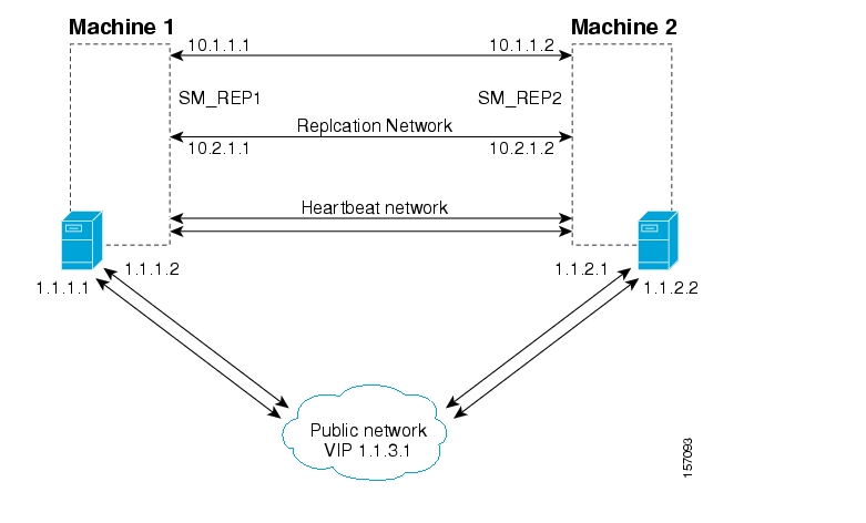
To configure the replication network shown by the above figure, do the following:
Configure the IP addresses of each of the replication NICs, each one in a different network. In this example, the IP addresses of the Machine1 replication NICs are 10.1.1.1 and 10.2.1.1.
Assign a hostname SM_REP1 to both of the local replication NIC IP addresses. In this example, the hostname SM_REP1 is assigned to the IP addresses of the replication NICs on Machine1. In the /etc/hosts file, be sure to also assign the local hostname (Machine1) to the local replication NICs. Ensure that there are no empty lines between the lines containing the local hostname.
Assign a hostname SM_REP2 to both of the remote replication NIC IP addresses. In this example, the hostname SM_REP2 is assigned to the IP addresses of the replication NICs of Machine2
The /etc/hosts file on Machine1 should appear as follows:
127.0.0.1   localhost
1.1.1.1     Machine1    loghost
10.1.1.1    Machine1    SM_REP1    REP_1_NIC_1
10.2.1.1    Machine1    SM_REP1    REP_1_NIC_2
10.1.1.2    SM_REP2       REP_2_NIC_1
10.2.1.2    SM_REP2       REP_2_NIC_2
The /etc/hosts file on Machine2 should appear as follows:
127.0.0.1   localhost
1.1.2.1     Machine2    loghost
10.1.1.2    Machine2    SM_REP2       REP_2_NIC_1
10.2.1.2    Machine2    SM_REP2       REP_2_NIC_2
10.1.1.1    SM_REP1    REP_1_NIC_1
10.2.1.1    SM_REP1    REP_1_NIC_2
Note
Make sure the system uses the /etc/hosts file before it performs DNS or any other name service operation.
The sections below assume that the following operations were performed before starting the VCS configuration:
Installation of the VCS on both machines. As part of this installation:
Each machine was given a hostname, which is used as the system name for the VCS configuration.
The machines are configured to recognize each other’s hostname.
An IP address was allocated for the cluster (hereafter, the cluster’s IP).
The SM and the TimesTen database were installed on both machines.
The SM VCS agents were installed on each machine.
The VCS manager Java console was installed on the administrator PC.
Note that in an SM cluster, two SM machines are connected to each other in a fully redundant way. The connection uses four cables: two for the VCS heartbeat mechanism, and two for the TimesTen database replication mechanism. Each machine is connected to the network via one of two redundant NICs. To access the cluster, you should use the cluster IP address, which is a virtual IP managed by the VCS. For management operations, you should use the local IP address of each machine.
To configure the VCS with the SM cluster resources, perform the procedures described in the following sections
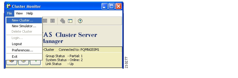
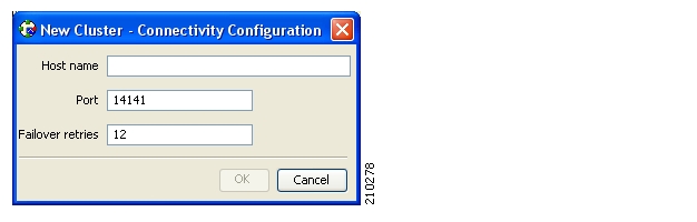
To add a service group to the cluster:
In the cluster explorer, from the service group tab, right-click the cluster, and select .
The Add Service Group window appears.
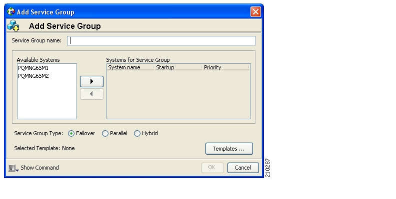
Enter a name for the service group.
Add the two machines as part of the service group and define their priority in the cluster.
Click OK.
This section describes how to set the auto-start parameters that define which machine will start after a boot of both nodes. If these parameters are not set, then at boot of both nodes the cluster will stay offline.
To set the auto-start parameters:
From the service group display, click .
Make sure that both nodes are defined in the AutoStartList (see the following figure).
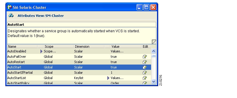
Specify which node will start by defining the AutoStartPolicy parameter.
Make sure that the AutoStart parameter is set to
true(iffalse, both nodes will come up as standby).
This section describes how to add the various SM cluster resources.
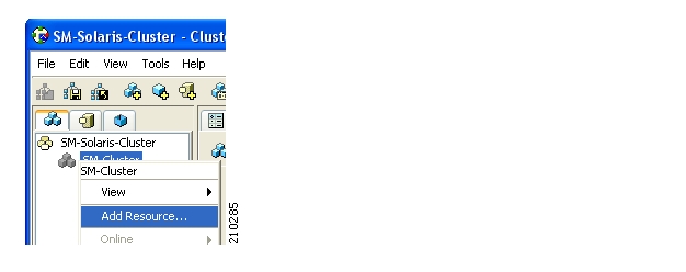
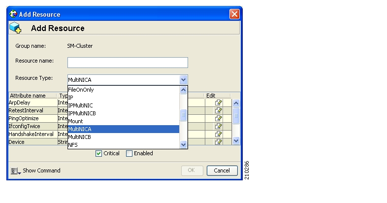
To add a Network NIC:
Decide which two network interfaces to use for the network connection.
Add a MultiNICA resource called Network-NICs to the service group.
Define the following parameter:
Device—Write the names of the Network NICs in the KEY column and their corresponding IP addresses in the VALUE column.
Note: Use the LOCAL option and configure each machine separately, because the IP addresses are different in each machine.
In the following example,
bge0andbge3are the network NICs.
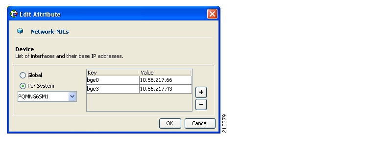
NetMask—Assign a relevant network mask. For example, 255.255.255.255 can be defined as a network mask.
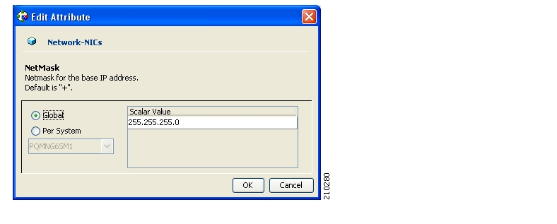
Check the and attributes of the resource (see the following figure):
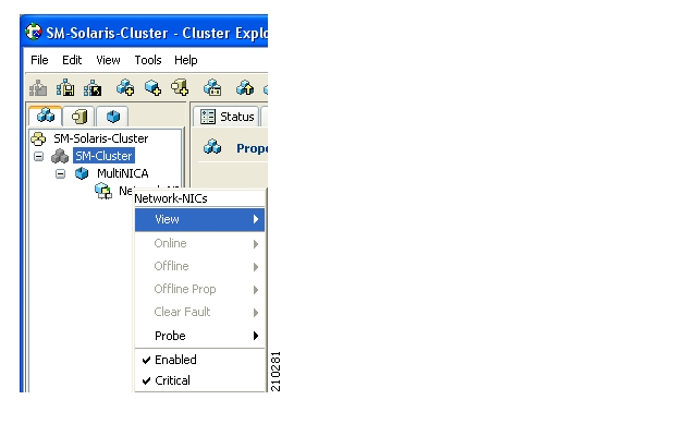
To add a Network VIP:
Decide on the IP address of the cluster.
Add to the service group an IPMultiNIC resource called Network-VIP.
Define the following parameters:
Address—Type the Cluster IP address.
Net-mask—Type the network-mask you want to use for this IP.
MultiNICAResName—Type Network-NICs to specify the relevant NICs.
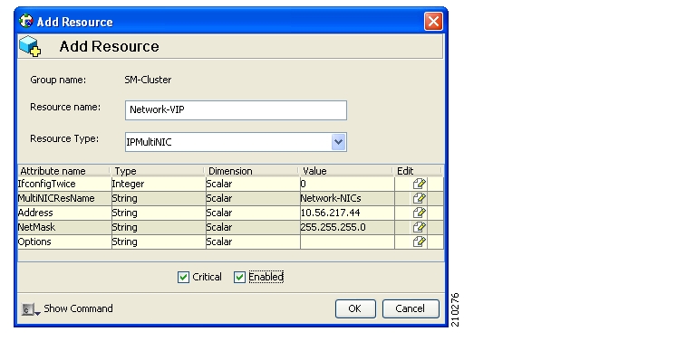
Set the resource to be and (see Adding Network NICs).
To add an SM resource:
Import the SubscriberManager agent’s type from file
/opt/VRTSvcs/bin/SubscriberManager/SubscriberManager.cf.Add to the service group a SubscriberManager resource called SM.
Define the following parameters:
SmBinPathName—Type the path to the
bindirectory under the SM installation directory; for example,/opt/pcube/sm/server/bin/.SmDebugLevel—Type a number between 1 and 4 to view debug messages, type 0 to disable debug messages.
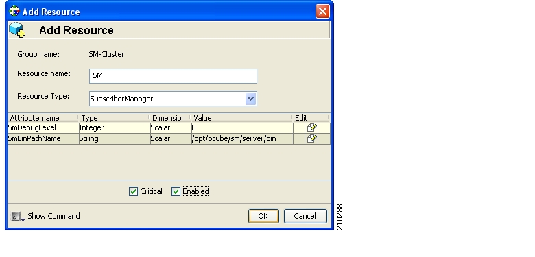
To add a TimesTen Daemon Resource:
Import the OnOnlyProcess agent’s type from file
/opt/VRTSvcs/bin/OnOnlyProcess/OnOnlyProcess.cf.Add to the service group an OnOnlyProcess resource called “TimesTenDaemon".
Define the following parameters (see following figure):
OnlineCmd—Type the TimesTen Daemon start command:
/etc/init.d/tt_pcubesm22 start.PathName—Type the TimesTen Daemon process path; for example,
/opt/pcube/lib/tt/TimesTen/pcubesm22/bin/timestend.Arguments—To view the arguments, run the following command of the machine:
ps–eaf | grep timestendFor example, the arguments can be: -initfd 13
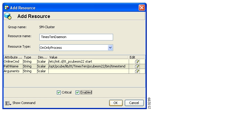
To add a TimesTen replication agent resource:
Import the TimesTenRep agent’s type from file
/opt/VRTSvcs/bin/TimesTenRep/TimesTenRep.cf.Add to the service group a TimesTenRep resource called ReplicationAgent.
Define the following parameters (see following figure):
TtBinPathName—Type the TimesTen bin directory path; for example,
/opt/pcube/lib/tt/TimesTen/pcubesm22/bin.TtDebugLevel—Type a number in the range of 1-4 for viewing debug messages; enter 0 for disabling the debug messages.
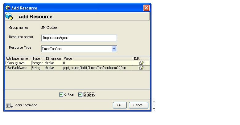
The following sections are useful operations for the management of the VCS.
After you have added the cluster, click the  icon: a login window appears.
Use the initial user and password (user: admin; password: password) for logging in.
Click the  icon, or from the menu select .
Before exiting the VCS make sure to save your configuration; otherwise, your configuration will be lost.
Click the  icon, or from the menu select .
Before exiting the VCS, make sure your configuration is closed. Some operations (like rebooting the system) could fail or cause a configuration conflict if performed while the configuration is in read/write mode.
To configure the SM Veritas agents, you first have to import the type file of these agents. This operation is performed by selecting from the menu . A navigation window appears:
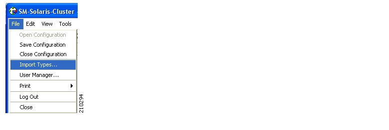
The window navigates through one of the cluster-system’s file system. Go to the agent directory under /opt/VRTSvcs/bin/<agent-dir> where there is a file whose name extension is .cf. Select this file (see following figure).
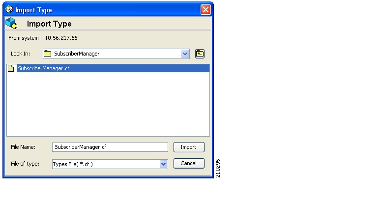
You can see the resource’s parameters in the following window:
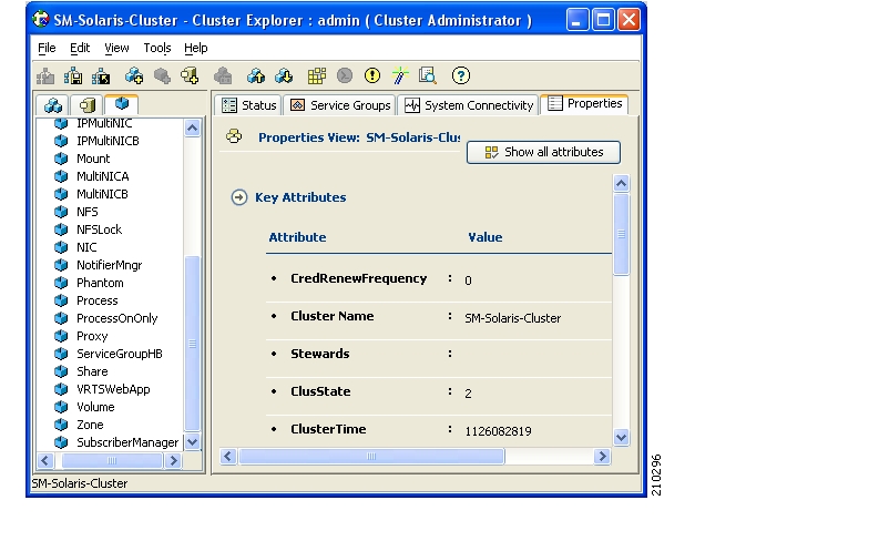
Linking the resources defines the order of becoming online and going offline.
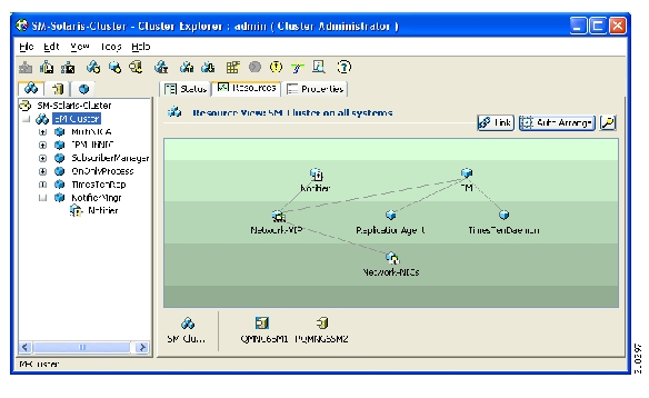
Remember to save your work at the end of the configuration process (see Saving the Configuration and Closing the Configuration).
Check that all of the resources are online/offline, according to the system and the resource type.
Note
The TimesTen Daemon, the NICs, and the TimesTen Replication Agent should all be online on all of the systems.
The state should be similar to the following figure:
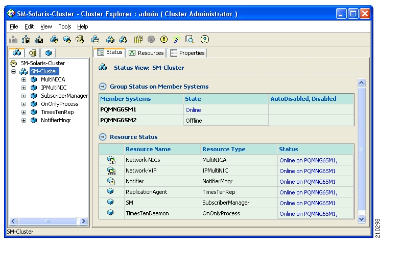
VCS provides a method for notifying the user of important events such as a resource or system fault. For this purpose, VCS supplies a NotifierMngr agent that enables the reception of messages from VCS and the delivery of those messages to SNMP consoles. This section describes configuring NotifierMngr in order to enable SNMP support.
Add and configure NotifierMngr using either the command line or the Cluster Manager Java Console.
When started from the command line, Notifier is a process that VCS does not control.
For best results, use the NotifierMngr agent bundled with VCS to configure Notifier as part of a highly available service group, which can then be monitored, brought online, and taken offline.
The following sections describe the configuration process using the Cluster Manager Java Console.
Add NotifierMngr as a resource to the SM Cluster service group.
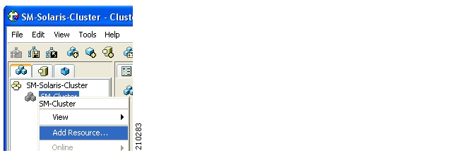
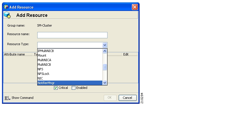
After adding the NotifierMngr resource, configure its attributes.
To configure the NotifierMngr attributes:
Select NotifierMngr as a Resource Type; the following screen appears:
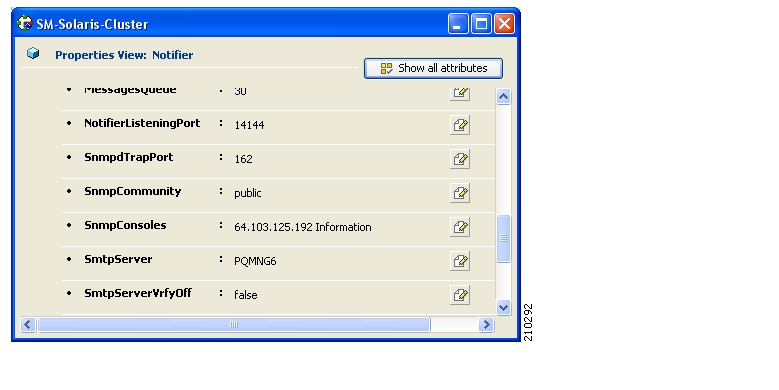
Define the following parameters (see the above figure):
SnmpConsoles—Specify the machine name of the SNMP manager and the severity level of messages to be delivered to the SNMP manager. The severity levels of messages are Information, Warning, Error, and SevereError. Specifying a given severity level for messages generates delivery of all messages of equal or higher severity.
SnmpdTrapPort—Specify the port to which the SNMP traps are sent. The value specified for this attribute is used for all consoles if more than one SNMP console is specified. The default is
162.SnmpCommunity—Specify the community ID (a string scalar) for the SNMP manager. The default is
public.
The SnmpConsole attribute specifies the IP addresses to which you want the SNMP traps to be sent. You can specify different trap severity for each IP address:
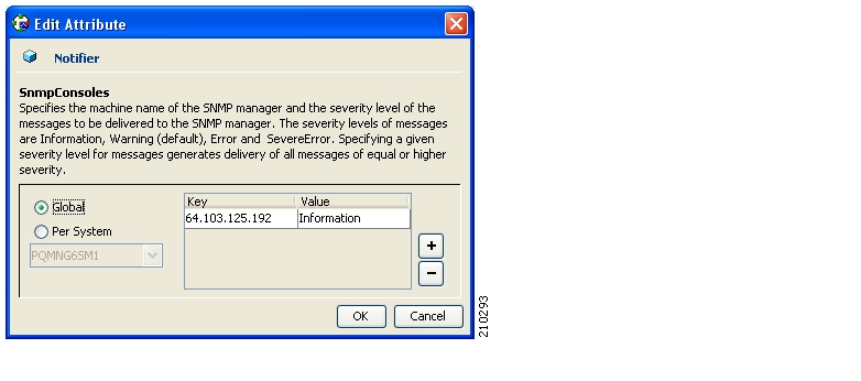
To link to IPMultiNIC:
Using the resources viewer, connect the Notifier to the Network-VIP resource so that it will be online after the VIP.
For more information, see the figure in Adding TimesTen Replication Agent Resources.
After adding and configuring NotifierMngr, it will send traps according to the configured severity to the destinations configured by the SnmpConsole Attribute.
View these traps using SNMP trap viewer/MIB Browser (for example, AdventNet MibBrowser).
For a complete list of traps/severities, please see Chapter 10 of the VERITAS Cluster Server User Guide.