- 1. Documentation and Resources
- 2. Prepare for Installation
- 3. Rack-Mount the SCE 2000
- 4. Connect the Power Supply Units
- 5. Connect the Management Interfaces and Perform Initial System Configuration
- Connect the Local Console
- Initial System Configuration
- Setup Command Parameters
- Step 1: Configuring Initial Settings
- Step 2: Configuring the Hostname
- Step 3: Setting the Passwords
- Step 4: Configuring Time Settings
- Step 5: Configuring the DNS Settings
- Step 6: Configuring the RDR Formatter Destination
- Step 7: Configuring Access Control Lists (ACLs)
- Step 8: Configuring SNMP
- Step 9: Configuring the Topology-Dependent Parameters
- Step 10: Completing and Saving the Configuration
- Connect the Management Interface
- 6. Cable the Line Ports
- 7. Completing the Installation
- 8. Installing a Cascaded System
- 9. Troubleshoot Startup Problems
- 10. Obtaining Technical Assistance
Documentation for the SCE 2000 platform is online and orderable. For detailed hardware installation instructions, refer to the online SCE 2000 Installation and Configuration Guide.
The following sections provide sources for obtaining documentation from Cisco Systems.
You can access the most current Cisco documentation on the World Wide Web at the following sites:
Cisco documentation and additional literature are available in a CD-ROM package that ships with your product. The Documentation CD-ROM is updated monthly and may be more current than printed documentation. The CD-ROM package is available as a single unit or as an annual subscription.
Cisco documentation is available in the following ways:
Registered Cisco Direct Customers can order Cisco Product documentation from the networking Products MarketPlace:
Registered Cisco.com users can order the Documentation CD-ROM through the online Subscription Store:
Nonregistered Cisco.com users can order documentation through a local account representative by calling Cisco corporate headquarters (California, USA) at 408 526-7208 or, in North America, by calling 800 553-NETS(6387).
If you are reading Cisco product documentation on the World Wide Web, you can submit technical comments electronically. Click Feedback in the toolbar and select Documentation. After you complete the form, click Submit to send it to Cisco.
You can e-mail your comments to bug-doc@cisco.com.
To submit your comments by mail, use the response card behind the front cover of your document, or write to the following address:
Attn Document Resource Connection Cisco Systems, Inc. 170 West Tasman Drive San Jose, CA 95134-9883
We appreciate your comments.
This section contains warnings, information about tools and parts, site preparation information, and information for workbench or tabletop installation and rack-mount installation.
Warning
This warning symbol means danger. You are in a situation that could cause bodily injury. Before you work on any equipment, be aware of the hazards involved with electrical circuitry and be familiar with standard practices for preventing accidents. To see translations of the warnings that appear in this publication, refer to the translated safety warnings that accompanied this device.
Warning
Only trained and qualified personnel should install, replace, or service this equipment.
Warning
Read the installation instructions before you connect the system to its power source.
Warning
This unit is intended for installation in restricted access areas. A restricted access area is where access can only be gained by service personnel through the use of a special tool, lock and key, or other means of security, and is controlled by the authority responsible for the location.
Warning
Voltage is present on the backplane when the system is operating. To reduce risk of an electric shock, keep hands and fingers out of the power supply bays and backplane areas.
Warning
Do not work on the system or connect or disconnect cables during periods of lightning activity.
Before beginning the installation of the SCE 2000, read the Regulatory Compliance and Safety Information for the Cisco Service Control Engine document.
Lift the SCE 2000 platform safely out of the packing container.
Ensure the power service at the site is suitable for the SCE 2000 platform.
Check the packing slip to ensure that all the proper components are present.
Locate and have accessible the Site Log for recording information about this installation.
Use the following list of tools and parts as a checklist for preparing for installing the SCE 2000 platform:
Appropriate cables to connect the SCE 2000 to the network and console terminal
Tape measure (optional)
Level (optional)
Number 1 Phillips screwdriver
Number 2 Phillips screwdriver
1/4-inch flat-blade screwdriver
1/4-inch hex wrench
Grounding kit (shipped with SCE 2000)
12 AWG or 2.5 mm copper installation wire with hex or loop connectors for DC power leads (DC power only)
Ring terminals must be UL approved and suitable for 12 AWG wire.
AC power cords (AC power only, shipped with SCE 2000)
Rack-mounting kit (shipped with SCE 2000)
Spare screws for changing bracket position
Before you begin the rack-mounting tasks, determine the type of rack—four-post or two-post—that you will be using.
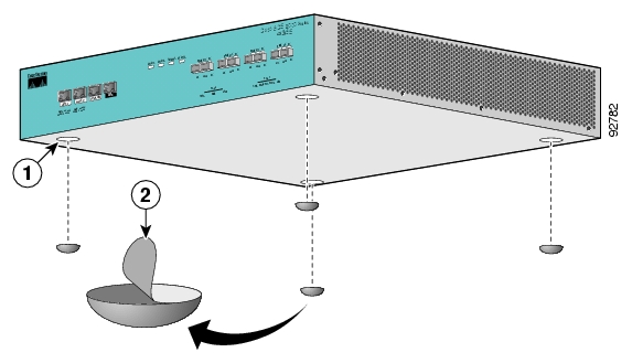
For a workbench or tabletop installation, verify the following before installing the SCE 2000 platform:
The SCE 2000 platform is off the floor and has adequate ventilation.
An adequate chassis ground (earth) connection exists for the SCE 2000 platform.
The SCE 2000 platform has at least 2 inches (5 cm) of clearance at each side and at least 5 inches (12.7 cm) of clearance at the rear to allow proper air flow.
Remove the adhesive strips from the four rubber feet and affix the feet onto the four marked locations on the bottom panel of the unit.
Place the SCE 2000 platform on the tabletop or workbench.
This section provides information for rack-mounting the SCE 2000 platform.
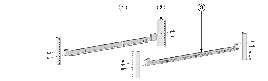
There are two standard types of equipment racks, and the appropriate brackets for each are provided in the enclosed kit.
19” rack with front rack posts — the mounting kit includes two mounting brackets as illustrated below:

19” rack with front and back rack posts — in addition to the mounting brackets illustrated below, the mounting kit includes two crossrail supports that the unit slides onto.

The SCE 2000 mounts to the two front rack posts with brackets that attach to the front of the SCE 2000 The inside width between the two posts or mounting strips (left and right) must be at least 17.3 inches (44 cm).
Note
Remember to leave a two-inch (5 cm) clearance on both sides of the SCE 2000 and at the rear for adequate airflow for the inlet and exhaust vents.
Before installing the SCE 2000 in the rack, you must first install an appropriate rack-mount bracket on each side of the front of the SCE 2000, as illustrated in the following figures.
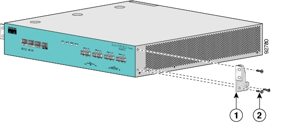
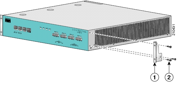
To install the rack-mount brackets on the SCE 2000 chassis, complete the following steps:
Before installing the SCE 2000 in the rack, you must first install a rack-mount bracket on each side of the front of the SCE 2000.
Align the rack-mount bracket to the side of the SCE 2000. Choose the proper bracket for your installation (2-post rack or 4-post rack) as illustrated in Rack-Mount the SCE 2000.
Insert and tighten three screws.
Repeat steps 1 and 2 on the other side of the SCE 2000.
If mounting the SCE 2000 in a rack with only two posts, skip to Mounting the System to a Rack.
If mounting the SCE 2000 in a rack with four posts, proceed to the next step to attach the crossrail supports to the rack.
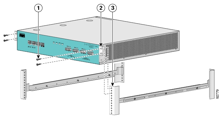
This section provides information for assembling the crossrail supports and attaching them to the rack.
When mounting in a rack with four posts (front and back) the two crossrail supports are mounted one on each side of the rack. The SCE 2000 then slides into these crossrails, which support the weight of the unit.
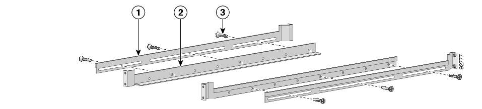
Assemble the two crossrail supports. Use three screws for each crossrail assembly.
Make sure that they are oriented so that both crossrails will support the SCE 2000 when they are attached to the rack.
Align the crossrail supports with the side of the rack, parallel to the floor.
Insert and tighten two screws to the front posts or mounting strips of the rack
Insert and tighten two screws to the Back posts of the rack.
Repeat steps 2 and 3 on the other side of the rack, keeping the brackets flush against the posts and parallel to the supporting bracket on first side of the rack.
When the appropriate mounting brackets are securely installed, the SCE 2000 can be installed into the rack.
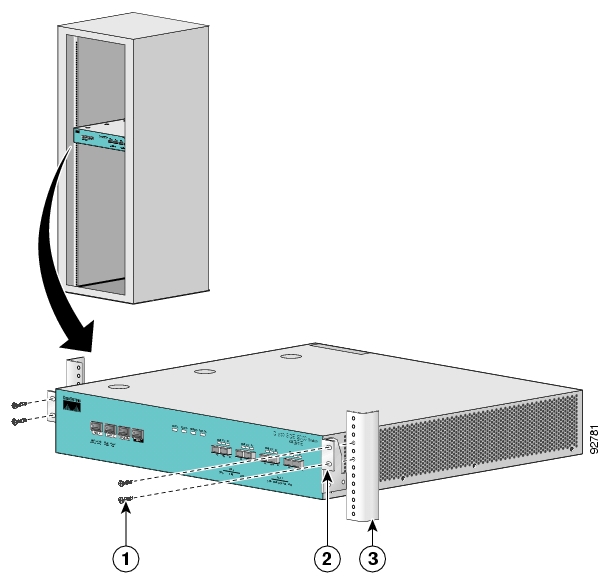
Make sure that the rack brakes are locked or that the rack is otherwise stabilized.
Position the SCE 2000 so that the front end is closest to you, and lift it carefully to place it into the rack. To prevent injury, avoid sudden twists or moves.
Slide the SCE 2000 into the rack, pushing it back until the brackets (installed at the front of the SCE 2000) meet the mounting strips or posts on both sides of the rack.
A rack with both front and back posts will have the crossrail supports installed. Slide the SCE 2000 onto these crossrails and push it all the way back.
While keeping the brackets flush against the posts or mounting strips, align the holes in the brackets with the holes on the rack or mounting strip.
For each bracket, insert and tighten two appropriate screws to the rack.
Note
Since the brackets support the weight of the entire SCE 2000 chassis, be sure to use all four screws to fasten the two rack-mount brackets to the rack posts.
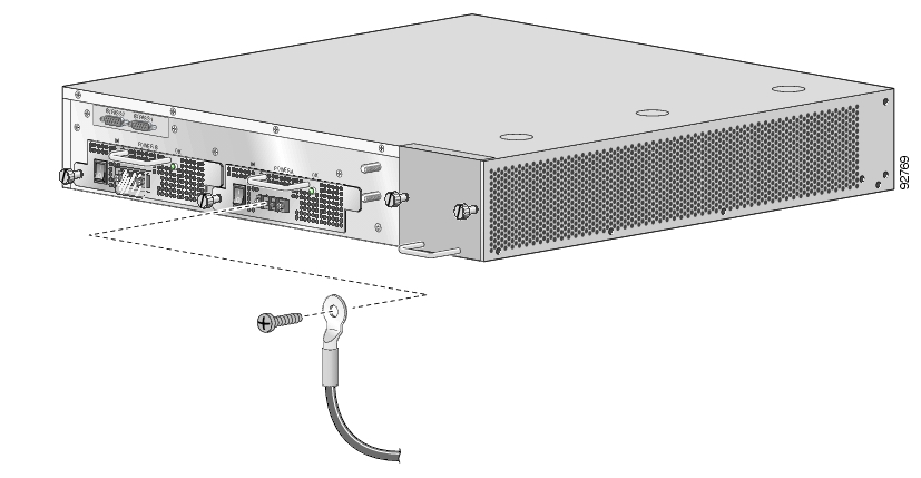
This section provides information for grounding the SCE 2000 platform and connecting the AC or DC power supply units.
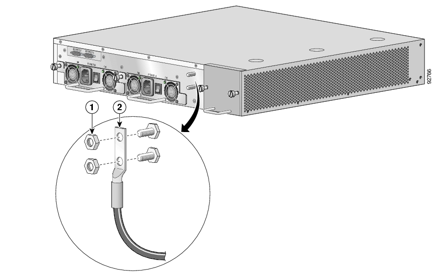
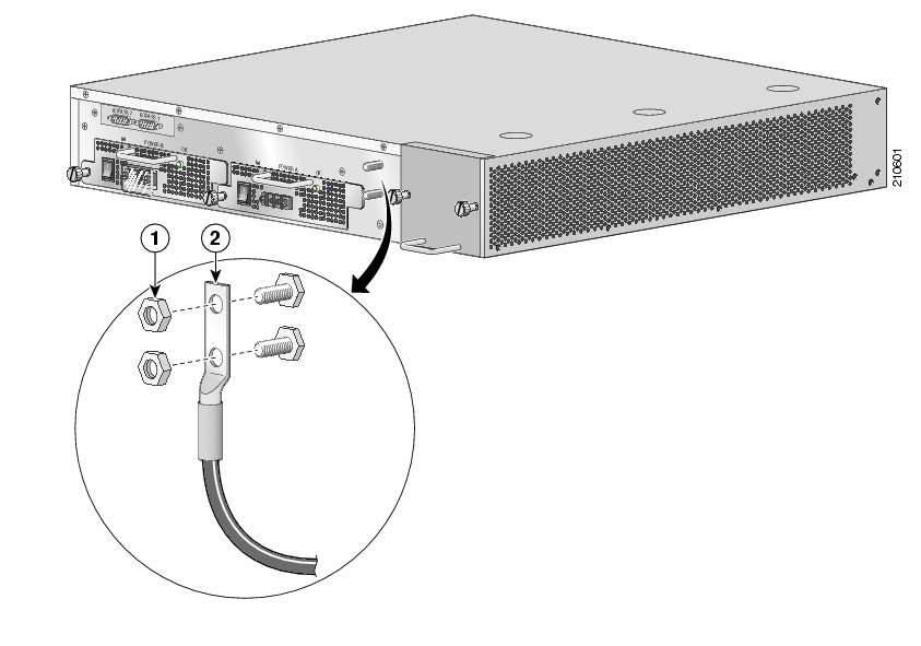
A Grounding kit is provided with each SCE 2000. Use this Grounding kit to properly ground the SCE 2000 chassis.
Warning
When installing the unit, the chassis ground connection must always be made first and disconnected last.
On the rear panel of the SCE 2000, locate the chassis grounding connector (refer to the appropriate figure for an AC- or DC-powered SCE 2000 above).
Attach the grounding cable (green and yellow colored cable), firmly fastening the (enclosed) hex nuts and spring washers with a #¼” hex wrench (refer to the appropriate figure for an AC- or DC-powered SCE 2000 above).
The other side of the grounding cable must be connected to the site equivalent of the AC earth.
The following sections describe how to reconnect the AC or DC power:
Warning
Before completing any of the following steps, and to prevent short-circuit or shock hazards, ensure that power is removed from the DC circuit. To ensure that all power to the power supply unit is OFF, locate the circuit breaker on the panel board that services the DC circuit, switch the circuit breaker to the OFF position, and tape the switch handle of the circuit breaker in the OFF position.
Note that the power to the relevant power supply unit should be off, not necessarily all power to the SCE 2000 platform. One DC-input power supply can be running when the other power supply is being removed or replaced.
Warning
Wiring should be done by a professional in accordance with state and local electrical codes.
Ensure that the DC power line input leads are disconnected from the power source.
Using the number 2 Phillips screwdriver, remove the protective plate from the terminal block.
Insert one receptacle screw into the hex or loop connector on one power line input, insert the screw with the connector into the corresponding lead receptacle and tighten the receptacle screw using the number 2 Phillips. Repeat for the remaining power line input lead.
Note
The color coding of the DC-input power supply leads depends on the color coding of the DC power source at your site. Make certain the lead color coding you choose for the DC-input power supply matches lead color coding used at the DC power source.
Note
Use 12 AWG (2.5 mm) copper wire only with hex or loop connectors. Ring terminals must be UL approved and suitable for 12 AWG wire.
Using the number 2 Phillips screwdriver, securely fasten the protective plate to the terminal block.
Connect the DC power line input leads to the DC power source through a fast 10A circuit breaker.
Turn the on/off switch to the on position.
Look at the IN and OK LEDs on the power supply unit and the corresponding Power LED on the front panel. If the DC-input power supply unit is operating properly, these LEDs will be glowing green.
Ensure that the power supply is properly aligned and the installation screw is tightened.
This completes the steps for reconnecting the DC-input power supply to the SCE 2000 platform.
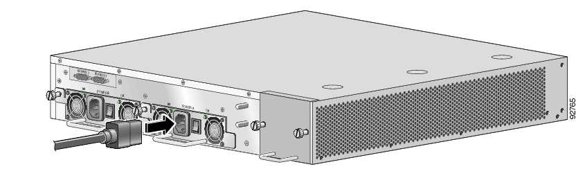
Plug the AC-input power cable into the AC-input power receptacle on the AC-input power supply
Note
For AC-input power, we recommend powering the SCE 2000 platform from a 120 VAC, 15A receptacle U.S. (240 VAC, 10A international) at the power source.
15 A branch circuit protection is recommended.
Plug the AC power supply cable into the AC power source.
Turn the on/off switch to the on position.
Look at the IN and OK LEDs on the power supply unit and the corresponding Power LED on the front panel. If the AC-input power supply unit is operating properly, these LEDs will be glowing green.
Ensure that the power supply is properly aligned and the installation screw is tightened.
This section explains how to connect the SCE 2000 platform to a local console and perform the initial system configuration via the setup wizard that runs automatically.
Additionally, this section contains instructions for cabling the Fast Ethernet Management interface.
Note
When installing a cascaded system, it is extremely important to follow the sequence of procedures outlined in the section Installing a Cascaded System.
You must first connect the unit to a local console and configure the initial settings for the SCE 2000 to support remote management. When the initial connection is established, the setup utility will run automatically, prompting you to perform the initial system configuration.
Make sure that the terminal configuration is as follows:
9600 baud
8 data bits
No Parity
1 stop bits
No flow control
The above SCE 2000 port parameters are fixed and are not configurable.
Plug the RS-232 serial cable provided with the SCE 2000 into the CON port on the front panel of the SCE 2000.
Connect the other end of the serial cable (with an attached DB-9 connector) to the VT100 compatible local (serial) terminal.
At the console. press Enter several times until the Cisco logo appears on the local terminal and the setup configuration dialog is entered.
                --- System Configuration Dialog ---

At any point you may enter a question mark ‘?’ followed by ‘Enter’ for help.
Use ctrl-C to abort configuration dialog at any prompt.
Use ctrl-Z to jump to the end of the configuration dialog at any prompt.
Default settings are in square brackets ‘[]’.

Would you like to continue with the System Configuration Dialog? [yes/no]: y
Type y and press Enter.
The system configuration dialog begins.
Upon initial connection to the local terminal, as described above, the system configuration wizard automatically runs to guide the user through the entire setup process. The wizard prompts for all necessary parameters, displaying default values, where applicable. You may accept the default values or define other values.
With the exception of the time settings, which take effect immediately when entered, the new configuration is applied and saved only at the end of the dialog when approved by the user. Therefore, if the setup dialog is aborted, no change takes place in the configuration, other than time settings (if entered).
When the dialog is complete, you may review the new configuration before applying it. The system displays the configuration, including parameters that were not changed. The system also displays any errors that are detected in the configuration. When the configuration is satisfactory, you may apply and save the new configuration.
The following table lists all the parameters included in the initial configuration. It is recommended that you obtain values for any parameters that you will configure at this time before beginning the setup.
Note
For further information regarding any configuration step or specific parameter, refer to the relevant section in the Cisco Service Control Engine (SCE) Software Configuration Guide.
Table 5.1. Setup Command Parameters
|
Parameter |
Definition |
|---|---|
|
IP address |
IP address of the SCE 2000. |
|
subnet mask |
Subnet mask of the SCE 2000. |
|
default gateway |
Default gateway. |
|
hostname |
Character string used to identify the SCE 2000. Maximum 20 characters. |
|
admin password |
Admin level password. Character string from 4-100 characters beginning with an alpha character. |
|
root password |
Root level password. Character string from 4-100 characters beginning with an alpha character. |
|
password encryption status |
Enable or disable password encryption? |
|
Time Settings |
|
|
time zone name and offset |
Standard time zone abbreviation and minutes offset from UTC. |
|
local time and date |
Current local time and date. Use the format: 00:00:00 1 January 2002 |
|
SNTP Configuration |
|
|
broadcast client status |
Set the status of the SNTP broadcast client. If enabled, the SCE will synchronize its local time with updates received from SNTP broadcast servers. |
|
unicast query interval |
Interval in seconds between unicast requests for update (64 – 1024) |
|
unicast server IP address |
IP address of the SNTP unicast server. |
|
DNS Configuration |
|
|
DNS lookup status |
Enable or disable IP DNS-based hostname translation. |
|
default domain name |
Default domain name to be used for completing unqualified host names |
|
IP address |
IP address of domain name server. ( maximum of 3 servers) |
|
RDR Formatter Destination Configuration | |
|
IP address |
IP address of the RDR-formatter destination |
|
TCP port number |
TCP port number of the RDR-formatter destination |
|
Access Control Lists |
|
|
Access Control List number |
How many ACLs will be necessary? What IP addresses will be permitted/denied access for each management interface? You may want ACLs for the following:
|
|
list entries (maximum 20 per list) |
IP address, and whether permitted or denied access. |
|
IP access ACL |
ID number of the ACL controlling IP access. |
|
telnet ACL |
ID number of the ACL controlling telnet access. |
|
SNMP Configuration |
|
|
SNMP agent status |
Enable or disable SNMP management. |
|
GET community names |
Community strings to allow GET access and associated ACLs (maximum 20). |
|
SET community names |
Community strings to allow SET access and associated ACLs (maximum 20). |
|
trap managers (maximum 20) |
Trap manager IP address, community string, and SNMP version. |
|
Authentication Failure trap status |
Sets the status of the Authentication Failure traps. |
|
enterprise traps status |
Sets the status of the enterprise traps. |
|
system administrator |
Name of the system administrator. |
|
Topology Configuration | |
|
connection mode |
Is the SCE 2000 installed using inline topology or receive-only topology using an optical splitter? |
|
type of deployment |
Is this a cascade topology, with two SCE 2000s connected via the cascade ports? Or is this a single platform topology? |
|
physically connected link (cascade topology only) |
In a cascade deployment this parameter sets the index for the link that this SCE 2000 is deployed on. The options for SCE 2000 are link-0 or link-1. In a single-SCE 2000 Platform deployment this parameter is not relevant since one SCE 2000 is deployed on both links. In this case the link connected to port1-port2 is by default link-0 and the link connected to port3-port4 is be default link-1. |
|
priority (cascade topology only) |
If this is a cascaded topology, is this SCE 2000 the primary or secondary SCE 2000? |
|
on-failure behavior (inline connection mode only) |
If this SCE 2000 is deployed inline, should the failure behavior be bypass or cutoff of the link? |
|
Admin status of the SCE 2000 after abnormal boot |
After a reboot due to a failure, should the SCE 2000 remain in a Failure status or move to operational status provided no other problem was detected? |
Following are some general instructions regarding the setup dialog:
All default values appear in square brackets [default].
If no value appears in the brackets [], or more than one option appears [yes/no], then this parameter does not have a default value.
To accept the default value, press Enter.
If you need more information about any parameter, type ? and press Enter.
A help message will appear describing the expected format of the parameter and any other requirements.
To jump to the end of the setup dialog at any point, accepting all remaining default values, press ^z.
In certain cases, there will be two or more logically related parameters within a menu. In these situations, it is not permitted to jump to the end of the setup dialog until all related parameters are configured. If you try to jump to the end of the setup dialog, the following message will appear: “
Sorry, Skipping is not allowed at this stage.”Certain groups of related parameters, such as time, date, and SNTP settings, form sub-dialogs or menus within the setup dialog. You may skip an entire menu, thereby accepting all default values for the parameters within the menu.
Each group of related parameters is prefaced by a question, asking whether you want to enter the menu. To skip the menu, answer no (“n”) to the question.
Example:
Would you like to enter the SNMP configuration menu? nTo abort the setup dialog at any point without making any configuration changes, press ^c. All changes already entered will be lost, with the exception of time settings.
Verify the following initial settings for the SCE 2000:
IP address
Subnet mask
Default gateway
All values are Internet addresses of the form ‘X.X.X.X’, where each letter corresponds to a decimal number between 0 and 255.
To configure the initial settings, complete the following steps:
The current IP address is displayed.
To accept the displayed value, press Enter.
To change the value, type the desired value in the format “x.x.x.x” and press Enter.
The current subnet mask is displayed.
To accept the displayed value, press Enter.
To change the value, type the desired value in the format “x.x.x.x” and press Enter.
The current IP address of the default gateway is displayed.
To accept the displayed value, press Enter.
To change the value, type the desired value in the format “x.x.x.x” and press Enter.
Example:
The following example displays a typical configuration of the IP address (10.1.5.109), subnet mask (255.255.0.0), and default gateway (10.1.1.3).
Since the IP address and the subnet mask are related, when the IP address is changed, there is no longer a default value of the subnet mask, and it must be entered explicitly.
Enter IP address [10.1.1.201]:10.1.5.109
Enter IP subnet mask:255.255.0.0
Enter IP address of default gateway [10.1.1.3]:
The hostname is used to identify the SCE 2000. It appears as part of the CLI prompt and is also returned as the value of the MIB-II object sysName.
The maximum length is 20 characters.
The default hostname is SCE 2000.
Configure the passwords as follows:
Set the password for each authorization level (User, Admin, Root).
Enable/disable password encryption. When password encryption is enabled, it encrypts the previously entered passwords.
Note
Passwords are needed for all authorization levels in order to prevent unauthorized users from accessing the SCE 2000. Admin level should be used by the network administrator. Root level is for use by Cisco technician.
Passwords must meet the following criteria:
Minimum length — 4 characters
Maximum length — 100 characters
Begin with an alpha character
May contain only printable characters
Note
Passwords are case sensitive.
Note
The default password for all levels is “cisco”.
To change the passwords, complete the following steps:
The default User password is displayed.
To accept the displayed value, press Enter.
To change the value, type the desired string and press Enter.
The default Admin password is displayed.
To accept the displayed value, press Enter.
To change the value, type the desired string and press Enter.
The default Root password is displayed.
To accept the displayed value, press Enter.
To change the value, type the desired string and press Enter.
Configure password encryption. By default, password encryption is not enabled.
To disable password encryption, press Enter.
To enable password encryption, type
yand press Enter.
Example:
Following is an example of changing all passwords. Password encryption is not enabled (default).
Enter a User password [cisco]:userinEnter an Admin password [cisco]:mng123Enter a Root password [cisco]:cistechEnable passwords encryption? [no]:
The time settings menu configures all time and date related parameters in the system. The time settings menu includes the following:
Time zone
Local time
Date
SNTP menu
You must enter the time setting menu in order to configure SNTP settings. You may choose to skip the time settings menu if you wish to accept all default values.
Note
Unlike all other settings defined in the system configuration, setting the time is done immediately and not at the end of the setup process.
To configure the time settings, complete the following steps:
Enter the time settings menu.
Would you like to enter the Time settings menu? [no]:yType
yand press Enter.The time settings dialog begins.
Type the time zone abbreviation and press Enter.
Enter time zone name [UTC]:
CETType the minutes offset from UTC and press Enter.
Enter time zone minutes offset from UTC:
60The local time and date are displayed, and you are asked whether you want to change them.
The local time and date is 15:00:01 CET FRI 01 July 2002
Would you like to set a new time and date? [no]:
If the time and date are correct, go to step5.
If the time and date are not correct, answer yes to the above question, and press Enter.
Would you like to set a new time and date? [no]:yConfirm your response and type the new time and date. This change will take effect immediately both on the system clock and calendar; it will also set the time zone you entered. Are you sure? [yes/no]: y Enter new local time and date:14:00:01 1 July 2002Time zone was successfully set. The system clock and the calendar were successfully set.You are asked whether you wish to enter the SNTP configuration menu.
If you do not wish to configure the SNTP, skip the rest of this section and go to Step 5: Configuring the DNS Settings.
To enter the SNTP configuration dialog, type
y, and press EnterWould you like to enter the SNTP configuration menu? [no]:yConfigure the SNTP broadcast client. By default the SNTP broadcast client is not enabled.
To disable the SNTP broadcast client, press Enter.
To enable the SNTP broadcast client, type
yand press Enter.Enable SNTP broadcast client? [no]:
Define the time interval between unicast updates.
To accept the displayed default value, press Enter.
To change the value, type the desired number of seconds (64 through 1024) and press Enter.
Enter time interval in seconds between unicast updates [1024]:
You may enter an IP address for the SNTP unicast server. Type in the hostname or the IP address in the form x.x.x.x, and press Enter
Would you like to configure SNTP unicast servers? [no]:
yEnter IP address or hostname of SNTP unicast server:10.1.1.1
Example:
Following is a sample time setting dialog. In addition to setting the time zone, time and date are changed, and SNTP unicast updates are configured.
Would you like to enter the Time settings menu? [no]: y
Enter time zone name [UTC]: ISR
Enter time zone minutes offset from UTC: 120
The local time and date is 15:35:23 ISR FRI July 19 2002
Would you like to set a new time and date? [no]: y
This change will take effect immediately both on the system clock
and the calendar; it will also set the time zone you entered.
Are you sure? [yes/no]: y
Enter new local time and date: 14:35:23 19 July 2002
Time zone was successfully set.
The system clock and the calendar were successfully set.
Would you like to enter the SNTP configuration menu? [no]: y
Enable SNTP broadcast client? [no]: y
Enter time interval in seconds between unicast updates [900]:
Would you like to configure SNTP unicast servers? [no]: y
Enter IP address or hostname of SNTP unicast server: 10.1.1.1The DNS configuration menu defines the IP address of the domain name server, which is used for DNS lookup, as well as the default domain name, which is used to complete unqualified host names.
You may choose to skip the DNS configuration menu if you wish to accept all default values.
To configure DNS settings, complete the following steps:
Enter the DNS settings menu.
Would you like to enter the DNS configuration menu? [no]:yType
yand press Enter.The DNS settings dialog begins.
Enable or disable DNS lookup.
To enable DNS lookup, press Enter.
To disable DNS lookup, type
nand press Enter.Enable IP DNS-based hostname translation? [yes]:
If you choose to disable DNS lookup, skip the rest of this section and go to Step 6: Configuring the RDR Formatter Destination. The rest of the dialog is not presented, as it is irrelevant when DNS lookup is disabled.
Type the default domain name to be used, and press Enter.
Note that there is no default domain name.
You may accept the default domain name or enter a new one.
Enter default domain name []:
Type the IP address of the primary domain name server and press Enter.
Enter Primary DNS IP address:
Note that there is no default for this parameter.
You may configure up to three domain servers.
Would you like to add another Name Server? [no]:
To exit the DNS settings dialog, press Enter.
To add another domain server, type
yand press Enter.You are asked to enter the IP address of the next domain name server.
Enter Secondary DNS IP address:
When IP addresses for all servers have been entered, exit the dialog by pressing Enter.
Would you like to add another Name Server? [no]:
Example:
Following is a sample DNS configuration dialog. The default domain name is pcube.com, and the IP address of the Domain Name Server is 10.1.1.230.
Would you like to enter the DNS configuration menu? [no]:yEnable IP DNS-based hostname translation? [yes]: Enter default domain name []:pcube.comEnter Primary DNS IP address:10.1.1.230Would you like to add another Name Server? [no]:
The SCE 2000 passes Raw Data Records (RDRs) to an external collection system via the RDR-Formatter. In order for the data to reach the correct location, the IP address of the external collection system and its port number must be configured.
To configure the RDR-formatter destination, complete the following steps:
Enter the RDR formatter configuration menu.
Would you like to enter the RDR-formatter configuration menu? [no]:yType
yand press Enter.The RDR-formatter destination dialog begins.
Type the IP address of the RDR-formatter destination and press Enter.
Enter RDR-formatter destination’s IP address:
Note that there is no default for this parameter.
Type the TCP port number of the RDR-formatter destination and press Enter.
Note that there is no default for this parameter.
Enter RDR-formatter destination’s TCP port number:
Example:
Following is a sample RDR-formatter configuration dialog, assigning the IP address and TCP port number.
Would you like to enter the RDR-formatter configuration menu? [no]:yEnter RDR-formatter destination’s IP address:10.1.1.230Enter RDR-formatter destination’s TCP port number:33000
The SCE 2000 can be configured with Access Control Lists (ACLs), which are used to permit or deny incoming connections on any of the management interfaces.
Note
ACL #0 is a pre-defined list that permits access to all IP addresses.
Configuration of access control lists is done in two stages:
Create the access control lists.
You may create 99 ACLs with a maximum of 20 entries per list. Each entry consists of an IP address, and an indication of whether access is permitted or denied to this IP address.
Assign the ACLs to the appropriate management interface. (See Step 9: Configuring the Topology-Dependent Parameters.)
The dialog permits you to skip the creation/editing of the ACLs and go directly to assigning ACLs to the management interfaces.
Each ACL may permit/deny access to any IP address, one or more ranges of IP addresses, or one or more individual IP address. Three entry formats are available to support these options:
Any IP address — Type the word “any”. Any IP address will be permitted or denied access.
Range of IP addresses — Type the beginning IP address in the desired range, then enter the wildcard bits that define the range.
This wildcard functions like a reverse mask, in that all “1” bits in the wildcard indicate the corresponding bit in the IP address should be ignored. All other bits must match the corresponding bit in the specified IP address. Refer to the table below for examples.
Each range of IP addresses can be configured to be permitted or denied access.
Individual IP address — Type the desired IP address, then enter the wildcard bits 0.0.0.0.
Each individual IP address can be configured to be permitted or denied access.
Table 5.2. IP address/Wildcard bit examples
|
Initial IP address |
Wildcard bits |
Range |
|---|---|---|
|
10.1.1.0 |
0.0.0.255 |
10.1.1.0–10.1.1.255 |
|
10.1.1.0 |
0.0.0.63 |
10.1.1.0–10.1.1.63 |
|
10.1.1.0 |
0.0.0.0 |
10.1.1.0 (individual entry) |
The order of the entries in the list is important. The entries in the list are tested sequentially, and the action is determined by the first entry that matches the connecting IP address. Therefore, when the entry “any” appears in an Access Control List, all succeeding entries are irrelevant.
Consider two hypothetical ACLs containing the same entries in a different order.
The following list would permit access to all IP addresses, including 10.1.1.0:
permit any
deny 10.1.1.0
Note that the above list could not actually be created using the setup utility, since after the “any” entry, no other entries could be added to the list.
The following list will deny access to IP address 10.1.1.0, but permit access to all others:
deny 10.1.1.0
permit any
If no entry in the assigned Access Control List matches the connection, or if the Access Control List is empty, the default action is deny.
To create the access control lists, complete the following steps:
Enter the Access Control Lists configuration menu.
Would you like to enter the Access lists configuration menu? [no]:yType
yand press Enter.The Access Control Lists configuration dialog begins.
You have the option of creating or modifying Access Control Lists, or skipping this section and proceeding directly to assign the existing ACLs to the desired management interfaces.
Would you like to create new Access lists or modify existing lists? [no]:
yIf you choose not to create or edit Access Control Lists, skip to Step 9: Configuring the Topology-Dependent Parameters.
Type the number of the Access Control List to be configured (1 through 99) and press Enter.
Note that there is no default for this parameter.
Begin adding entries to the selected list.
Indicate whether this entry is permitted access or denied access.
To permit access press Enter.
To deny access type
nand press Enter.Does this entry permit access? [yes]:
Type the IP address to be added to this list, and press Enter.
Type “
any” and press Enter to include any IP address in the ACL.Note that there is no default for this parameter.
Enter IP address or the word ‘any’ to denote any IP address:
If you entered a specific IP address, enter the wildcard bits to define a range of IP addresses and press Enter. (See Entry Formats.)
To define an individual IP address, type 0.0.0.0 and press Enter.
There is no default for this parameter.
Enter wildcard bits:
The maximum number of entries in an ACL is 20.
If the “any” option was used, no other IP addresses may be added to the list.
To add more entries, type
yand press EnterWould you like to add another entry to this list? [no]:
y
Enter up to 20 entries as described in step 5 and step 6.
When all entries have been added, press Enter
Would you like to add another entry to this list? [no]:
When all entries are added to one list, you are asked whether you would like to create another ACL. You may define up to 99 ACLs.
To create another ACL, type
yand press EnterWould you like to configure another list? [no]:
y
Enter up to 20 IP addresses in this new ACL, as described in step 5 and step 6.
When all ACLs have been created, press Enter.
Would you like to configure another list? [no]:
You are now prompted to assign the desired ACLs to restrict IP and Telnet access.
Restrict IP access to the SCE 2000 by assigning the appropriate ACL.
Type the number of the ACL to be assigned to IP access and press Enter.
To accept the default ACL, press Enter.
Enter IP access-class [0]:
Restrict Telnet access to the SCE 2000 by assigning the appropriate ACL.
Type the number of the ACL to be assigned to the Telnet interface and press Enter.
To accept the default ACL, press Enter.
Enter Telnet access-class [0]: 2
Example 1:
This example illustrates a common access control scenario. Let us assume the following:
We want to permit every station to access the SCE platform on the management port (e.g. ping, SNMP polling etc.).
We want to restrict Telnet access to only a few permitted stations.
We therefore need to create two access control lists:
For general IP access — permit access to all IP addresses.
For Telnet — permit access to the specified IP address, and deny to all others.
ACL #1 = permit any IP address. Assign to IP access.
ACL #2 = permit access to 10.1.1.0, 10.10.10.1, deny to all others. Assign to Telnet access.
Would you like to enter the Access lists configuration menu? [no]:yWould you like to create new Access lists or modify existing lists? [no]:yEnter ACL number:1Does this entry permit access? [yes]: Enter IP address or the word ‘any’ to denote any IP address:anyThis entry matches every IP address, no use in adding more entries to this list. Would you like to configure another list? [no]:yEnter ACL number:2Does this entry permit access? [yes]: Enter IP address or the word ‘any’ to denote any IP address:10.1.1.0Enter wildcard bits: 0.0.0.0Would you like to add another entry to this list? [no]:yDoes this entry permit access? [yes]: Enter IP address or the word ‘any’ to denote any IP address:10.10.10.1Enter wildcard bits: 0.0.0.0Would you like to add another entry to this list? [no]:yDoes this entry permit access? [yes]:n Enter IP address or the word ‘any’ to denote any IP address:anyThis entry matches every IP address, no use in adding more entries to this list. Would you like to configure another list? [no]: Enter IP access-class [0]:1Enter Telnet access-class [0]:2Example 2:
This example skips the first section of the dialog (creating/modifying), and proceeds directly to assign existing ACLs.
Would you like to enter the Access lists configuration menu? [no]:yWould you like to create new Access lists or modify existing lists? [no]: Enter IP access-class [0]:10Enter Telnet access-class [0]:22
Managing the SCE 2000 is possible also via a Network Management System (NMS) that supports SNMP. By default, SNMP is disabled on the SCE 2000.
To enable SNMP management you must configure the following basic SNMP parameters:
SNMP traps status and managers.
Community strings (where an SNMP community string is a text string that acts like a password to permit access to the SNMP agent on the SCE 2000).
To configure SNMP parameters, complete the following steps:
Enter the SNMP configuration menu.
Would you like to enter the SNMP configuration menu? [no]:yType
yand press Enter.The SNMP configuration dialog begins.
Enable SNMP management.
Type
yand press Enter.Enable SNMP management? [no]: y
If you choose to disable SNMP management, skip the rest of this section and go to Step 9: Configuring the Topology-Dependent Parameters. The rest of the dialog is not presented, as it is irrelevant when SNMP management is disabled.
Type the SNMP GET community name and press Enter.
The SNMP agent that resides inside the SCE 2000 will respond only to GET requests that use this community string.
Enter SNMP GET community name:
Note that there is no default for this parameter.
Assign an access list to restrict the SNMP management stations that may use this GET community.
Type a number (1 through 99) or type “0” to permit access to all IP addresses, and press Enter.
Enter Access list number allowing access with this community string, use ‘0’ to allow all:
The maximum number of GET communities is 20.
To add more entries, type
yand press EnterWould you like to add another SNMP GET community? [no]:
y
Enter up to 20 SNMP GET communities as described in step 3 and step 4.
When all entries have been added, press Enter
Would you like to add another SNMP GET community? [no]:
Type the SNMP SET community name and press Enter.
The SNMP agent that resides inside the SCE 2000 will respond only to SET requests that use this community string.
Enter SNMP SET community name:
Note that there is no default for this parameter.
Assign an access list to restrict the SNMP management stations that may use this SET community.
Type a number (1 through 99) or type “0” to permit access to all IP addresses, and press Enter.
Enter Access list number allowing access with this community string, use ‘0’ to allow all:
The maximum number of SET communities is 20.
To add more entries, type
yand press EnterWould you like to add another SNMP SET community? [no]:
y
Enter up to 20 SNMP SET communities as described in step 6 and step 7.
When all entries have been added, press Enter
Would you like to add another SNMP SET community? [no]:
Enter the SNMP trap managers menu.
Would you like to configure SNMP trap managers? [no]: yType
yand press Enter.The SNMP trap managers dialog begins.
If you choose not to configure SNMP trap managers, the dialog skips to the authentication failure trap status. (See step 14.)
Type the trap manager IP address and press Enter.
Enter SNMP trap manager IP address:
Note that there is no default for this parameter.
Type the trap manager community string and press Enter.
Note that there is no default for this parameter.
Enter SNMP trap manager community string:
Type the number of the trap manager SNMP version (1 or 2c) and press Enter
Note that there is no default for this parameter.
Enter trap manager SNMP version:
The maximum number of trap managers is 20.
To add more entries, type
yand press EnterWould you like to add another SNMP trap manager? [no]:
y
Enter up to 20 trap managers as described in step 10 through step 12.
When all entries have been added, press Enter
Would you like to add another SNMP trap manager? [no]:
Configure the Authentication Failure trap status.
To disable the Authentication Failure trap, press Enter.
To enable the Authentication Failure trap, type
yand press Enter.Enable the ‘Authentication Failure’ trap [no]:
Configure the SCE enterprise trap status.
To disable the SCE enterprise traps, type
npress Enter.To enable the SCE enterprise traps, type
yand press Enter.Enable the SCE enterprise traps []:
Type the name of the system administrator and press Enter.
Note that there is no default for this parameter.
Enter system administrator contact name []:
Example:
Following is a sample SNMP configuration, configuring one trap manager, one GET community, and one SET community, and enabling the authentication failure trap, as well as all enterprise traps.
Would you like to enter the SNMP configuration menu? [no]:yEnable SNMP management? [no]:yEnter SNMP GET community name[]:publicEnter Access list number allowing access with this community string, use ‘0’ to allow all:0Would you like to add another SNMP GET community? [no]: Enter SNMP SET community name[]:privateEnter Access list number allowing access with this community string, use ‘0’ to allow all:2Would you like to add another SNMP SET community? [no]: Would you like to configure SNMP trap managers? [no]:yEnter SNMP trap manager IP address:10.1.1.253Enter SNMP trap manager community string:publicEnter trap manager SNMP version:2cWould you like to add another SNMP trap manager? [no]: Enable the ‘Authentication Failure’ trap [no]:yEnable SCE enterprise traps []: y Enter system administrator contact name []:John Smith
The topology configuration menu is a series of guided questions relating to the deployment of the SCE 2000 in the network and its mode of operation. Values for the parameters are configured based on the user answers.
The correct value for each parameter must be ascertained before configuring the system to make sure that the system will function in the desired manner. (See Topology for a comprehensive discussion of topology and the related parameters.)
Note
Values may not be requested for all topology-dependent parameters, as certain parameters do not apply to all topologies.
There are six topology-related parameters:
Connection mode — Can be either of the following, depending on the physical installation of the SCE 2000.
Inline
Receive-only
Type of deployment — Can be one of the following, depending on the actual deployment:
Single-SCE Platform — a single SCE 2000 is deployed on one or two GBE links
Cascade — two cascaded SCE 2000s are deployed on two GBE links, working as a fully redundant solution.
Physically connected link (cascade topology only) — In a cascade topology, the user must assign an index to each of the links. This index is used to identify the services per link.
In a single-SCE platform deployment, the indices of the links cannot be changed by the user and are:
link-0 — the link connected to ports 1 and 2
link-1 — the link connected to ports 3 and 4
In a cascade deployment, the user must define which link is connected to which SCE 2000. The index must be different for each SCE 2000. In this case the user can choose one of the following:
Link-0 — the link connected to this SCE 2000 is identified as 0.
Link-1 — the link connected to this SCE 2000 is identified as 1.
Priority (cascade topology only) — In a cascade topology, this parameter determines which SCE 2000 is chosen as the active SCE 2000 in the “active election” procedure. This decision is taken only when both SCE 2000s are starting up together. If there is one working SCE 2000 and the other is just starting up, then the working one will automatically be chosen as active and the other one as standby. This parameter can be set to one of the following:
Primary
Secondary
On-Failure behavior — Determines the behavior of the SCE 2000 upon failure, or reboot. One of the following link modes may be chosen for the SCE 2000 in the cases of failure or reboot.:
Bypass — traffic is bypassed using the internal bypass card.
Cutoff — the link is forced down.
Admin status after abnormal reboot — This parameter determines whether the SCE 2000 returns to full operational mode after abnormal (not user-requested) boot, or stays in non-operational mode, in which the SCE 2000 behaves as in failure mode. This parameter can be set to one of the following:
Operational
Non-operational
The procedure described below is a presentation of all the questions in the topology configuration. In actual practice, all questions may not be presented for a particular configuration, depending on the topology deployed.
Study the examples that follow to understand the procedure for various topologies.
To configure topology dependent parameters, complete the following steps:
Enter the topology configuration menu.
Would you like to enter the Topology configuration menu? [no]: yType y and press Enter.
The topology configuration dialog begins.
Specify the connection mode.
To define inline connection mode, press Enter.
To define receive-only connection mode, type 2 and press Enter.
Enter Connection mode:
1- inline
2- receive-only
Enter your choice [1]:
Specify the deployment type.
To specify a Single-SCE Platform deployment, press Enter.
To specify a Cascade deployment, type y and press Enter.
Is this a cascade deployment? [no]:
Specify the physically-connected-link index.
To specify link-0, press Enter.
To specify link-1, type 1 and press Enter.
Enter Physically connected link:
0- link-0
1- link-1
Enter your choice [0]:
Specify the SCE 2000 priority.
To specify Primary, press Enter.
To specify Secondary, type 2 and press Enter.
Enter SCE 2000 priority:
1- primary
2- secondary
Enter your choice [1]:
Specify the On-failure link behavior.
To specify Bypass, press Enter.
To specify Cutoff, type 2 and press Enter.
Enter On-failure behavior:
1- bypass
2- cutoff
Enter your choice [1]:
Specify the status of the SCE 2000 after abnormal boot.
To specify Operational status after abnormal boot, press Enter.
To specify Not-Operational status after abnormal boot, type 2 and press Enter.
Enter admin status of the SCE after abnormal boot:
1- Operational
2- Not-Operational
Enter your choice [1]:
The following examples present the procedure for configuring the topology-related parameters for various topologies.
Example 1:
Following is a sample topology configuration for a non-redundant topology using an optical splitter, that is, a single SCE 2000 connected in receive-only connection mode, to one or two GBE links
Would you like to enter the Topology configuration menu? [no]: y
Would you like to enter the Topology configuration menu? [no]: y
Enter Connection mode:
1- inline
2- receive-only
Enter your choice [1]: 2
Is this a cascade deployment? [no]: no
Enter admin status of the SCE after abnormal boot:
1- Operational
2- Not-Operational
Enter your choice [1]: 1

Data collection for the system configuration is completed.
All other parameter values are automatically assigned by the system.
Example 2:
Following is a sample topology configuration for a non-redundant inline topology. In this topology, a single SCE 2000 is connected to one or two GBE links.
When the inline connection mode is specified, the user must specify the on-failure link behavior.
Would you like to enter the Topology configuration menu? [no]: y
Enter Connection mode:
1- inline
2- receive-only
Enter your choice [1]: 1
Is this a cascade deployment? [no]: no
Enter On-failure behavior:
1- bypass
2- cutoff
Enter your choice [1]: 1
Enter admin status of the SCE after abnormal boot:
1- Operational
2- Not-Operational
Enter your choice [1]: 1

Data collection for the system configuration is completed.
Example 3:
Following is a sample topology configuration for a secondary SCE 2000 in a redundant inline topology. In this topology there are two SCE 2000s that are cascaded via the cascade GBE ports (ports 3 and 4). Each SCE 2000 is connected inline to both sides (subscribers/network) of one GBE link.
In this case, the user must specify the physically-connected-link index (link-0 in our example), the priority of the SCE 2000, and the on-failure link behavior.
Would you like to enter the Topology configuration menu? [no]: y
Enter Connection mode:
1- inline
2- receive-only
Enter your choice [1]: 1
Is this a cascade deployment ? [no]: yes
Enter Physically connected link:
0- link-0
1- link-1
Enter your choice [0]: 0
Enter SCE 2000 priority:
1- primary
2- secondary
Enter your choice [1]: 2
Enter On-failure behavior:
1- bypass
2- cutoff
Enter your choice [1]: 1
Enter admin status of the SCE after abnormal boot:
1- Operational
2- Not-Operational
Enter your choice [1]: 1

Data collection for the system configuration is completed.When you have completed the entire configuration, the system checks for errors. If errors are found, a warning message appears. When the configuration is error-free, you may apply and save it.
To complete and save the configuration, complete the following steps:
The system informs you that data collection is complete.
We recommend that you view the entire new configuration before it is applied.
Type y and press Enter.
Note that there is no default.
If there are no errors, go to step 3.
Data collection for the system configuration is completed.
Would you like to view the new configuration before it is applied? [yes/no]: y
If any errors are detected, you may choose to view them.
Press Enter.
Found errors in the new configuration, would you like to view them? [yes]:
The following errors were found:
Warning - RDR formatter destination 10.1.1.1 is not allowed in the IP access-class.
You are asked whether to apply and save the configuration.
Apply and Save this configuration? [yes/no]:To apply and save the configuration, type y and press Enter.
To abort the setup procedure without applying or saving the configuration (recommended if there are errors), type n and press Enter.
Setup procedure aborted, no configuration changes made.
If the setup is aborted, the dialog is ended.
If there are no errors, the system requests confirmation of either a yes or no answer, in order to prevent mistakes.
Type the appropriate answer (y or n) and press Enter.
The running configuration would be overwritten by the changes you have just entered, are you sure? [yes/no]:
The selected action is carried out by the system.
If the apply and save action is not confirmed (no), the setup is aborted.
Setup procedure aborted, no configuration changes made.
If the apply and save action is confirmed (yes), the configuration is applied and saved.
The new running configuration will be saved to the startup configuration.
If the configuration was applied and saved, you may also save it to a file at a remote station.
Do you want to save a copy of the startup configuration file in a remote station? [no]:
To save the configuration to a remote station, type y and press Enter.
The system will ask for FTP path:
Enter a full FTP path of the remote destination:
The system informs you that the configuration is complete.
Committing configuration...

Configuration completed successfully.

Saving configuration...
Writing general configuration file to temporary location...
Backing-up general configuration file...
Copy temporary file to final location...

Done!
This completes the procedures for initial configuration of the SCE 2000 platform.
Example 1:
Following is an example of a configuration that the user aborted due to errors detected in the configuration.
Note that no confirmation is requested for the decision to abort the setup. Had there been no errors, confirmation would have been requested before aborting.
Data collection for the system configuration is completed.
Would you like to view the new configuration before it is applied? [yes/no]: n
Found errors in the new configuration, would you like to view them? [yes]: y
The following errors were found:
Warning - RDR formatter destination 10.1.1.1 is not allowed in the IP access-class.
Warning - default Gateway 10.1.1.1 is not allowed in the IP access-class.
Warning - IP Access list (1) conflicts with Telnet Access list (2) as follows:
Access list 2 permits all addresses while Access list 1 denies it.
Apply and Save this configuration? [yes/no]: n

Setup procedure aborted, no configuration changes made.
Example 2:
Following is an example of a configuration that was applied and saved to the startup configuration as well as to an FTP site.
Although not demonstrated in this example, it is recommended that you always view the configuration before applying it.
Data collection for the system configuration is completed.
Would you like to view the new configuration before it is applied? [yes/no]:
Apply and Save this configuration? [yes/no]: y

(New configuration would be displayed here)

The running configuration would be overwritten by the changes you have just entered, are you sure? [yes/no]:y

The new running configuration will be saved to the startup configuration.
Do you want to save a copy of the startup configuration file in a remote station? [no]:y
Enter a full FTP path of the remote destination: ftp://vk:vk@10.1.1.253/h:/copyofstartup.txt
Committing configuration...

Configuration completed successfully.

Saving configuration...
Writing general configuration file to temporary location...
Backing-up general configuration file...
Copy temporary file to final location...

Done!
Example 3:
Following is an example of a configuration that was aborted, although no errors were detected.
Data collection for the system configuration is completed.
Would you like to view the new configuration before it is applied? [yes/no]:
Apply and Save this configuration? [yes/no]: n
The changes you have just entered would be discarded, are you sure? [yes/no]:y

Setup procedure aborted, no configuration changes made.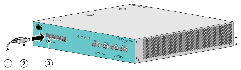
Note
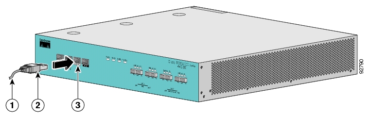
By default, the management port is configured to auto-negotiation enabled.
The SCE 2000 has two management ports, labeled Mng1 and Mng 2. Use the Mng 1 port.
Plug the Ethernet cable provided (with attached RJ-45 connector) into the Mng 1 port on the front panel of the SCE 2000.
Connect the other end of the Ethernet cable into your management network.
The Link LED on the SCE 2000 management port should light up.
Test connectivity. From the host that you intend to use for remote management, ping to the SCE 2000 by typing ping and the SCE 2000 IP address, and pressing Enter (see the example, below).
This verifies that an active connection exists between the specified station and the management port.
Example:
The following example displays a typical ping response where the target IP address is 10.1.1.201.
C:\>ping 10.1.1.201
pinging 10.1.1.201 ...
PING 10.1.1.201: 56 data bytes
64 bytes from host (10.1.1.201): icmp_seq=0. time=0. ms
64 bytes from host (10.1.1.201): icmp_seq=1. time=0. ms
64 bytes from host (10.1.1.201): icmp_seq=2. time=0. ms
64 bytes from host (10.1.1.201): icmp_seq=3. time=0. ms
----10.1.1.201 PING Statistics----
4 packets transmitted, 4 packets received, 0% packet loss
round-trip (ms) min/avg/max = 0/0/0This section provides instructions for cabling the Gigabit Ethernet ports for both one and two SCE 2000 topologies, and for configuring Gigabit Ethernet (GBE) interface parameters. In a topology utilizing two SCE 2000s (cascade), this includes the cascade ports as well as the line ports.
Warning
Class 1 laser. Avoid exposure to radiation and do not stare into open aperture.
Note
When installing a cascaded system, it is extremely important to follow the sequence of procedures outlined in the section Installing a Cascaded System.
Before beginning, find the appropriate cabling diagram for the topology in your installation:
Single SCE 2000 topologies
Dual SCE 2000 topologies (cascaded)
Note
When installing a cascaded system, it is extremely important to follow the sequence of procedures outlined in the section Installing a Cascaded System.
In the inline topology, the SCE 2000 resides physically on the GBE (Gigabit Ethernet) link between the subscribers, which are usually connected through either a BRAS (in DSL access), a PDSN (in wireless access), a CMTS (in the Cable access), or a switch or router aggregator (in other topologies), and the network, where the SCE 2000 usually connects to a router or layer 3 switch network element.
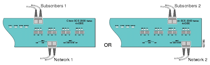
In the single link inline topology, either the first GBE link (first two ports) of the SCE 2000 or the second GBE link (third and fourth ports) can be used, as illustrated in the diagram above. The remaining pair of ports is unused.
Either port 1 or port 3 is used for connecting to the network element that is deployed on the subscriber side of the SCE 2000 while port 2 or port 4 is used for connecting to the network element that is deployed on the network side of the SCE 2000.
Inline topology requires both Receive and Transmit fibers
In this topology, an optical splitter resides physically on the GBE link that the SCE 2000 should monitor. The optical splitter is connected to the SCE 2000 via Rx links only.
In this topology, the traffic passes through the optical splitter, which splits traffic to the SCE 2000.
Note
Receive-only topologies can also be implemented using a switch. Such a switch must support SPAN functionality that includes separation between ingress and egress traffic and multiple SPAN-ports destinations.
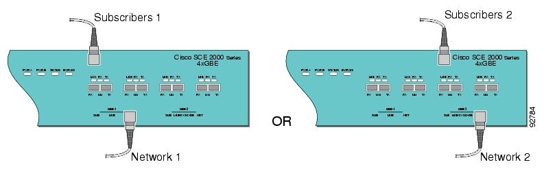
The single link receive-only topology cabling is similar to that for single link inline, in that either the first GBE link (first two ports) or the second GBE link (third and fourth ports) can be used, as illustrated in the diagram above. The remaining pair of ports is unused.
Either port 1 or port 3 is used for connecting to the network element that is deployed on the subscriber side of the SCE 2000 while port 2 or port 4 is used for connecting to the network element that is deployed on the network side of the SCE 2000.
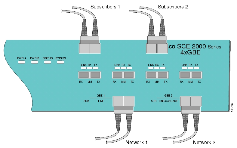
In this topology, one SCE 2000 is connected to two full duplex, GBE links. The SCE 2000 may be either inline, to support both monitoring and traffic control functionality, or receive-only for traffic monitoring functionality only.
When one SCE 2000 supports two links, the first two ports are connected to one link, while ports 3 and 4 are connected to the second link as follows;
Port 1: Link 1, Subscriber side
Port 2: Link 1, Network side
Port 3: Link 2, Subscriber side
Port 4: Link 2, Network side
As with the single link cabling, inline topologies require both Receive and Transmit fibers, while Receive-only systems use only Receive fibers.
Note
Receive-only topologies can be implemented using either an optical splitter or a switch. If a switch is used, it must support SPAN functionality that includes separation between ingress and egress traffic and multiple SPAN-ports destinations.
The following two diagrams illustrate the connections for dual links, with a single SCE 2000 deployed for both inline and receive-only topologies.
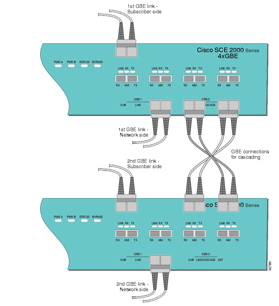
In this topology, two SCE 2000s are connected to two full duplex, GBE links, providing full redundancy through cascading the two SCE 2000s. The SCE 2000s may be either inline, to support both monitoring and traffic control functionality, or receive-only for traffic monitoring functionality only.
Note
When installing a cascaded system, it is extremely important to follow the sequence of procedures outlined in the section Installing a Cascaded System.
Note
Receive-only topologies can be implemented using either an optical splitter or a switch. If a switch is used, it must support SPAN functionality that includes separation between ingress and egress traffic and multiple SPAN-ports destinations.
When two SCE 2000s are used, the first two ports in each SCE 2000 are connected to the links, while ports 3 and 4 are the cascade ports that are used for communicating between the two SCE 2000s as follows:
SCE 2000 #1
Port 1: Link 1, Subscribers side
Port 2: Link 1, Network side
Port 3: Cascade, connect to Port 4 in SCE 2000 #2
Port 4: Cascade, connect to Port 3 in SCE 2000 #2
SCE 2000 #2
Port 1: Link 2, Subscribers side
Port 2: Link 2, Network side
Port 3: Cascade, connect to Port 4 in SCE 2000 #1
Port 4: Cascade, connect to Port 3 in SCE 2000 #1
Note
Cascade ports must be connected directly in Layer 1 (dark fibers).
Inline topologies require connecting both Receive and Transmit fibers to the SCE 2000. Cascade ports always require both Receive and Transmit fibers to be connected.
The following diagram illustrates the connections for a dual link, two SCE 2000 inline topology
By default, the SCE 2000 GBE line interface ports are configured with auto-negotiation disabled.
Note
Autonegotiation must be disabled when the SCE 2000 is deployed via an external optical splitter (receive-only topology)
Note
If you change any parameters, you must save the new configuration settings.
Type copy running-config startup-config, and press Enter
To enter the Global Configuration Mode, at the SCE 2000# prompt, type configure, and press Enter.
The SCE 2000(config)# prompt appears.
To enter the desired GBE port interface, type interface GigabitEthernet 0/
portnumber, and press Enter, whereportnumberis the number of the selected port (1-4).The SCE 2000(config if)# prompt appears.
Type auto-negotiate and press Enter.
The SCE 2000(config if)# prompt appears.
To return to Global Configuration Mode, type exit and press Enter.
The SCE 2000(config)# prompt appears.
Repeat this procedure to configure auto-negotiation for the other GBE port interfaces as needed.
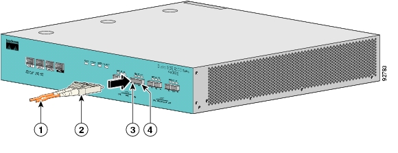
Refer to Cabling Diagrams to find the appropriate cabling diagram for the topology of your system for the specific connections required.
The following table presents the fiber specifications. The SCE 2000 may be ordered with either Multimode or Single Mode transceivers The transceiver type is indicated on the front panel under the ports. Note that both transceivers on any individual SCE 2000 are the same, either 850nm Multimode OR 1310nm Single Mode.
Table 6.1. Fiber Specifications
|
SCE Model |
Transceiver |
Transmit Power |
Receive Power |
Typical (Max.) Distance |
|---|---|---|---|---|
|
SCE 2000 4xGBE MM |
850nm Multimode |
–9.5 to –4 dBm |
–17 to 0 dBm |
|
|
SCE 2000 4xGBE SM |
1310nm FRP laser Single Mode |
–9.5 to –3 dBm |
–20 to 3 dBm |
10 km for 9.0µm Core Diameter SMF |
Plug the specified fiber optic cable (see Fiber Specifications) into the appropriate GBE port on the front panel of the SCE 2000.
Verify that the link LED is green.
If the link LED does not light, try removing the network cable plug and reinserting it firmly into the module socket.
This section discusses how to verify link connectivity and how to install a Service Control application.
The GBE Link LED must be green in order to verify that an active connection exists.
The GBE Rx and Tx LEDs (if flashing green) indicate that traffic is being received or transmitted by the SCE 2000 platform, respectively.
Note that in an inline topology, the Rx and Tx LEDs indicate that packets are being received/transmitted by the SCE 2000 platform.
In optical splitter topologies, the Rx LEDs are the sole indicators. The Tx LEDs do not “blink”, since the Tx is not connected to the port in this topology.
The procedures for performing the final tests to verify that the SCE 2000 is functioning properly are explained in the following sections:
After all the ports are connected, verify that the SCE 2000 is not in a Warning state.
To verify that the SCE 2000 is not in a warning state, complete the following steps:
On the SCE 2000 Front panel, examine that the Status LED is flashing green.
To display the operation status of the system, at the
SCE 2000#prompt, typeshow system operation-statusand press Enter.A message displaying the operation status of the system appears. If the system is operating in order, the following message appears:
System Operation status is Operational.
Example:
The following example displays a sample output where the LEDs appear red/orange:
SCE 2000#show system operation-statusSystem Operation status is Operational
View the user log for errors that occurred during the installation process.
To display the user log device counters, complete the following steps:
At the
SCE 2000#prompt, typeshow logger device User-File-Log countersand press Enter.
Example:
The following example shows the current User-File-Log device counters.
SCE 2000#show logger device user-file-log counters
Logger device User-File-Log counters:
Total info messages: 1
Total warning messages: 0
Total error messages: 0
Total fatal messages: 0
If there are “Total error messages” or “Total fatal messages”, use the show logger device User-File-Log command to display details about the errors.
When you enter configuration commands, it immediately effects the SCE platform operation and configuration. This configuration, referred to as the running-config, is saved in the SCE platform volatile memory and is effective while the SCE platform is up. After reboot, the SCE platform loads the startup-config, which includes the non-default configuration as saved by the user, into the running-config.
The SCE platform provides commands for:
Viewing the running configuration
Viewing the startup configuration
After configuring the SCE platform, you may query for the running configuration using the command show running-config. This command displays the non-default running configuration. To view all SCE platform running configuration, whether it is the default or not, you may use the option all-data in the show running-config command.
To view the running configuration, complete the following steps:
At the
SCE 2000#prompt, typeshow running-config.The system shows the running configuration.
SCE 2000#show running-config
#This is a general configuration file (running-config).
#Created on 15:50:56  CET  MON  December  11  2005
#cli-type 1
#version 1

clock timezone CET 1
snmp-server community “public” ro
snmp-server host 10.1.1.253 traps version 1 “public”
interface LineCard 0
connection-mode active
no silent
no shutdown
flow-aging default-timeout UDP 60
interface FastEthernet 0/0
ip address 10.1.5.109 255.255.0.0
interface FastEthernet 0/1
interface FastEthernet 0/2
exit
line vty 0 4
no timeout
exit
SCE 2000#
One of the useful show commands is the show version command. This command displays global static information on the SCE 2000 as software and hardware version, image build time, system uptime, last open packages names and information on the SLI application assigned.
To show the version information for the SCE 2000 software and hardware, complete the following steps:
At the
SCE 2000#prompt, typeshow version.The system shows the version information.
SCE 2000#show version
System version: Version 3.0.0 Build 240
Build time: Jan 11 2006, 07:34:47
Software version is: Version 2.5.2 Build 240
Hardware information is:
rx            : 0x0075
dp            : 0x1808
tx            : 0x1708
ff            : 0x0077
cls           : 0x1721
cpld          : 0x0025
Lic           : 0x0176
rev           : G001
Bootrom       : 2.1.0
L2 cache      : Samsung 0.5
lic type      : MFE
optic mode    :
Part number: 53AA-BXC1-AAAA
Revision: A02A
Software revision: G001
Serial number: 043P6982
Power Supply type: AC

SML Application information is:
Application file: /tffs0/temp.sli
Application name:
Application help:
Original source file: H:\work\Emb\jrt\V2.5\sml\actions\drop\drop_basic_anyflow.san
Compilation date: Wed, December 21 2005 at 21:25:21
Compiler version: SANc v2.50 Build 32 gcc_codelets=true built on: Tue December 23 2005 09:51:57 AM.;SME plugin v1.1
Default capacity option used.


Logger status: Enabled


Platform: SCE 2000 - 4xFE
Management agent interface version: SCE Agent 3.0.0 Build 18
Software package file: ftp://vk:vk@10.1.8.22/P:/EMB/LatestVersion/3.0.0/se1000.pkg

SCE 2000 uptime is 21 minutes, 37 seconds
SCE 2000#
Another useful show command is the show system-uptime command. This command displays information similar to the last line above, which indicates how long the system has been running since the last reboot.
To show the system uptime for the SCE platform software and hardware, complete the following steps:
At the
SCE 2000#prompt, typeshow system-uptime.The system shows how long the system has been running since the last reboot.
SCE 2000#show system-uptime
SCE 2000 uptime is 21 minutes, 37 seconds
SCE 2000#
When you make changes to the current running configuration and you want those changes to continue to be valid when the system restarts, you must save the changes before leaving the management session, that is, you must save the running configuration to the startup configuration file.
The SCE platform provides multiple interfaces for the purpose of configuration and management. All interfaces supply an API to the same database of the SCE platform and any configuration made through one interface is reflected through all interfaces. Furthermore, when saving the running configuration to the startup configuration from any management interface, all configuration settings are saved regardless of the management interface used to set the configuration.
To save configuration changes, complete the following steps:
At the
SCE 2000#prompt, typeshow running-configto view the running configuration.The running configuration is displayed.
Check the displayed configuration to make sure that it is set the way you want. If not, make the changes you want before saving.
Type
copy running-config startup-config.The system saves all running configuration information to the configuration file, which is used when the system reboots.
The configuration file holds all information that is different from the system default in a file called config.txt located in the directory: tffs0:system.
Example:
The following example shows the running configuration file.
SCE 2000#show running-config
#This is a general configuration file (running-config).
#Created on 15:50:56  CET  MON  February  11  2006
#cli-type 1
#version 1

clock timezone CET 1
snmp-server community “public” ro
snmp-server host 10.1.1.253 traps version 1 “public”
interface LineCard 0
connection-mode active
no silent
no shutdown
flow-aging default-timeout UDP 60
interface FastEthernet 0/0
ip address 10.1.5.109 255.255.0.0
interface FastEthernet 0/1

interface FastEthernet 0/2

exit
line vty 0 4
no timeout
exit
SCE 2000#
SCE 2000#copy running-config startup-config
Writing general configuration file to temporary location...
Backing-up general configuration file...
Copy temporary file to final location...
SCE 2000#
For backup purposes, the old startup-config file is saved under the directory: tffs0:system/prevconf. Refer to Recovering a Previous Configuration for an explanation on how to recover previous configuration.
To remove a configuration command from the running-config, use the no form of the command.
Example:
The following example illustrates how to remove all DNS settings from the running configuration.
SCE 2000(config)#no ip name-server
SCE 2000(config)#After you have installed your SCE 2000 platform hardware, checked all external connections, turned on the system power, allowed the system to boot up, and performed the initial system configuration, you might need to perform more complex configurations, which are beyond the scope of this publication.
For further information on system and interface configuration, refer to the following documents:
Cisco Service Control Engine (SCE) Software Configuration Guide
Cisco Service Control Engine (SCE) CLI Command Reference
The SCE 2000 platform provides the basic functionalities of Service Control analysis and enforcement. A Service Control solution requires that a Service Control application be loaded into the platform, to take advantage of the unique SCE platform capabilities.
Loading and activating an application includes the following stages:
Downloading the application provided as an SLI file to the SCE 2000 disk.
Activating the application.
Configuring the application.
The detailed procedure of how to perform these operations is not specified and described in this manual. For further details, refer to the following documentation:
Service Control Application for Broadband User Guide
Service Control Application for Broadband Reference Guide
This section outlines the installation procedures for a redundant solution with two cascaded SCE 2000s. For more complete information,refer to the Cisco SCE 2000 4xGBE Installation and Configuration Guide. Refer to the Cisco SCE 2000 4xGBE CLI Command Reference for details of the CLI commands.
Warning
When working with two SCE 2000s with split-flow and redundancy, it is extremely important to follow this installation procedure.
To install a cascaded system, complete the following steps:
Install both SCE 2000s, power them up, and perform the initial system configuration. (See Connect the Power Supply Units and Connect the Local Console.)
Connect both SCE 2000s to the management station.(See Connect the Management Interface)
Connect the cascade ports. The cascade ports must be connected directly in Layer 1 (dark fibers), not through switches. (See Dual Link: Two SCE 2000s Topology.)
Set topology configurations for each SCE 2000 via the connection-mode options. (See Topology-Related Parameters for Redundant Topologies and Configuring the Connection Mode.)
Make sure that theSCE 2000s have synchronized and active SCE 2000 was selected.
Use the
show interface linecard 0 connection-modecommand.If you want to start with bypass/sniffing, change the link mode to your required mode in both SCE 2000s on both links. The bypass mode will be applied only to the active SCE 2000. (See Link Mode.)
Make sure that the link mode is as you required.
Use the
show interface linecard 0 link modecommand.Connect the traffic port of SCE 2000 #1. This will cause a momentary down time until the network elements from both sides of the SCE 2000 auto-negotiate with it and start working (when working inline). (See Dual Link: Two SCE 2000s Topology.)
Connect the traffic port of SCE 2000 #2, this will cause a momentary down time until the network elements from both sides of the SCE 2000 auto-negotiate with it and start working (when working inline). (See Dual Link: Two SCE 2000s Topology.)
When full control is needed, change the link mode on both SCE 2000s on both links to ‘forwarding’. It is recommended to first configure the active SCE 2000 and then the standby. (See Link Mode.)
You can now start working with the Subscriber Manager.
This section presents CLI commands relevant to the configuration and monitoring of a redundant system.
Use the following commands to configure and monitor a redundant system:
connection-mode
[no] force failure-condition
Show interface linecard 'number' connection-mode
Show interface linecard 'number' physically-connected linksAll four of the topology-related parameters are required when configuring a redundant topology.
Connection mode — Redundancy is achieved by cascading two SCE platforms. Therefore the connection mode for both SCE platforms may be either:
Inline-cascade
Receive-only-cascade
Physically-connected-links — For each of the cascaded SCE platforms, this parameter defines the number of the link (Link 0 or Link 1) connected to this SCE platform.
Priority — For each of the cascaded SCE platforms, this parameter defines whether it is the primary or secondary device.
On-failure — For each of the cascaded SCE platforms, this parameter determines whether the system cuts the traffic or bypasses it when the SCE platform either has failed or is booting.
Use the following command to configure the connection mode, including the following parameters:
inline/receive only
physically connected links
behavior upon failure of the SCE platform
primary/secondary
To configure the connection mode, use the following command:
From the SCE 2000(config if)# prompt, type
connection-modeinline-cascade/receive-only-cascade[physically-connected-links{link-0/link-1}][priority{primary/secondary}][on-failure{bypass/cutoff}]and press Enter.
Example 1
Use the following command to configure the primary SCE platform in a two-SCE platform inline topology. Link 1 is connected to this SCE platform and the behavior of the SCE platform if a failure occurs is bypass.
SCE 2000(config if)# connection-mode inline-cascade physically-connected-links link-1 priority primary on-failure bypassExample 2
Use the following command to configure the SCE platform that might be cascaded with the SCE platform in Example 1. This SCE platform would have to be the secondary SCE platform, and Link 0 would be connected to this SCE platform, since Link 1 was connected to the primary. The connection mode would be the same as the first, and the behavior of the SCE platform if a failure occurs is also bypass.
SCE 2000(config if)# connection-mode inline-cascade physically-connected-links link-0 priority secondary on-failure bypass
The SCE platform has an internal hardware card used to maintain the links even when the SCE platform fails. This hardware card has four possible modes of operation:
bypass
forwarding
cutoff
sniffing
Normally, the link mode is selected by the SCE platform software according to the configured connection-mode. However, the link-mode command can be used to enforce a specific desired mode. This may be useful when debugging the network, or in cases where we would like the SCE platform just to forward the traffic. (Note that this is only relevant to inline topologies even though the configuration is available also when in receive-only mode.)
The following link mode options are available:
Forwarding — forwards traffic on the specified link to the SCE platform for processing.
Bypass — stops all forwarding of traffic on the specified link to the SCE platform. Traffic still flows on the link, but is not processed in any way by the SCE platform.
This does not affect the redundancy states.
Sniffing — allows the SCE platform to forward traffic on the specified link through the bypass mechanism while still analyzing the traffic passively.
Sniffing is permitted to be configured for all links, only (use the all-links option).
Cutoff — completely cuts off flow of traffic through the specified link.
Note the following recommendations and restrictions:
Since the SCE 1000 platform has only one link, the link is not specified.
Since the SCE 2000 platforms have more than one link, it is required to specify the link. The link designations are different for the GBE and FE platforms, as follows:
SCE 2000 4xGBE — GBE1-GBE2/GBE3-GBE4
SCE 2000 4/8xFE — LINK1/LINK2
Use the
'all-links'option to configure the link mode for all links (SCE 2000 platforms only).It is recommended that both links be configured together. Use the all-links option.
Link mode is relevant only to inline topologies.
It is recommended that in cascaded topologies, both SCE platforms be configured for the same link mode, otherwise the service will be unpredictable.
Sniffing can only be configured for all links, therefore, to configure sniffing, the all-links option is required, not just recommended.
The default link mode is forwarding. When other link modes are selected, active service control is not available and any service control configuration will not be applicable.
Use the following commands to view the current connection mode and link mode parameters.
To view the current connection mode, use the following command:
From the SCE 2000# prompt, type
show interface linecard 0 connection-modeand press Enter.
The following table lists the operational states of the SCE 2000. The Status LED on the SCE 2000 Front Panel reflects the current SCE 2000 operational status. The operational status can be displayed using CLI command show system operation-status.
Table 9.1. SCE 2000 Operational States
|
SCE 2000 Operational Status |
Description |
Status LED State |
|---|---|---|
|
Booting |
Initial state after reset |
Orange |
|
Operational |
SCE 2000 becomes operational after completing the following process:
|
Flashing green |
|
Warning |
SCE 2000 is fully operational (as above) but one of the following occurred:
Note: If the condition that caused the SCE 2000 to be in Warning state is resolved (for example, link is up) the SCE 2000 reverts to Operational state. |
Flashing orange |
|
Failure |
System is in Failure state after Boot due to one of the following conditions:
Note: Depending on the cause of failure, the management interface and the platform configuration may or may not be active/available. |
Red |
Startup problems are commonly due to the source power or to a poor cable connection.
This section contains a detailed description of the normal startup sequence and describes the steps to take if the system does not perform that sequence as expected. LEDs indicate all system states in the startup sequence. By checking the state of the LEDs, you can determine when and where the system failed in the startup sequence. Use the following descriptions to isolate the problem to a subsystem, and then proceed to the appropriate sections to try to resolve the problem.
When you start up the system by turning on the power supply switch, the following should occur:
You should immediately hear the fans operating.
When all LEDs come on to indicate that the system has booted successfully, the initial system banner should be displayed on the console screen. If it is not displayed, see Connect the Local Console to verify that the terminal is set correctly and that it is properly connected to the console port.
If the banner is displayed, but the Status LED is flashing orange, indicating a warning state, check the user log:
At the prompt, type:
more user logIf any of the following warning messages appear, turn the SCE 2000 platform off and call technical support.
"voltage problem:"
"fans problem"
"abnormal raise in interior temperature:"
If the following warning message appears, delete unneeded files from the disk.
“insufficient disk space:”
Use the following commands to provide information to help you troubleshoot installation of your SCE 2000 platform. Refer to Cisco Service Control Engine (SCE) Software Configuration Guide or the Cisco Service Control Engine (SCE) CLI Command Reference for more information.
Note
Remember that if the management interface is not operational, you should connect the SCE 2000 platform to a local console so that you can enter CLI commands for troubleshooting.
Troubleshooting firmware package installation:
Boot system<filename> —Specifies and verifies the package file to be installed. Error messages or other output identify problems with the package file.Following is a sample output from the
Boot systemcommand.SCE 2000(config)#boot system ftp://vk:vk@10.1.1.230/downloads/SENum.pkg.pkg Verifying package file SENum.pkg.pkg… Package file verified OK.
Troubleshooting the management subsystem:
show interface
Mng—Displays IP address and auto-negotiation information for the management interfaces.Following is a sample output from the show interface
Mngcommand.ip address: 10.1.6.145 subnet mask: 255.255.0.0 Configured speed: auto, configured duplex: auto AutoNegotiation is On, link is Up, actual speed: 100, actual duplex: halfshow ip default-gateway — Displays the IP address of the configured default gateway.
Following is a sample output from the show ip default-gateway
Default gateway: 10.1.1.1show ip route — Displays the entire routing table and the destination of last resort (default-gateway).
Following is a sample output from the show ip route
gateway of last resort is 10.1.1.1
show access-lists — Shows all access-lists or a specific access list.
Following is a sample output from the show access-lists
Standard IP access list 1
    Permit 10.1.1.0, wildcard bits 0.0.0.255
    deny   any
show telnet — Displays the status of the telnet server daemon (
status) or any active Telnet sessions (sessions).Following is a sample output from the show telnet
show telnet sessions
There is 1 active telnet session:

Index | Source
================
 0    | 10.1.1.201
show telnet status
Telnet deamon is enabled.
show line vty timeout — Shows the timeout configured for Telnet sessions.
Following is a sample output from the show line vty timeout command.
Timeout is 30 minutes
Troubleshooting the link interface subsystem:
show interface
GigabitEthernet 0/# —Displays information for a specific GBE Interface.Following is a sample output from the show interface
ip address: 10.1.6.145
subnet mask: 255.255.0.0
Configured duplex: auto
AutoNegotiation is On, link is Up, actual duplex: half
show interface
GigabitEthernet 0/#counters — Displays the values of counters of a GBE interface.Following is a sample output from the show interface
counterscommand.In total octets: 191520 In good unicast packets: 560 In good multicast packets: 0 In good broadcast packets: 0 In packets discarded: 0 In packets with CRC/Alignment error: 0 In undersized packets: 0 In oversized packets: 0 Out total octets: 0 Out unicast packets: 0 Out non unicast packets: 0 Out packets discarded: 0
Refer to The User Log for an explanation of commands related to the user log.
Cisco provides Cisco.com as a starting point for all technical assistance. Customers and partners can obtain documentation, troubleshooting tips, and sample configurations from online tools. For Cisco.com registered users, additional troubleshooting tools are available from the TAC website.
Cisco.com is the foundation of a suite of interactive, networked services that provides immediate, open access to Cisco information and resources at any time, from anywhere in the world. This highly integrated Internet application is a powerful, easy-to-use tool for doing business with Cisco.
Cisco.com provides a broad range of features and services to help customers and partners streamline business processes and improve productivity. Through Cisco.com, you can find information about Cisco and our networking solutions, services, and programs. In addition, you can resolve technical issues with online technical support, download and test software packages, and order Cisco learning materials and merchandise. Valuable online skill assessment, training, and certification programs are also available.
Customers and partners can self-register on Cisco.com to obtain additional personalized information and services. Registered users can order products, check on the status of an order, access technical support, and view benefits specific to their relationships with Cisco.
To access Cisco.com, go to http://www.cisco.com.
The Cisco Technical Assistance Center (TAC) website is available to all customers who need technical assistance with a Cisco product or technology that is under warranty or covered by a maintenance contract.
If you have a priority level 3 (P3) or priority level 4 (P4) problem, contact TAC by going to the TAC website http://www.cisco.com/tac.
P3 and P4 level problems are defined as follows:
P3—Your network is degraded. Network functionality is noticeably impaired, but most business operations continue.
P4—You need information or assistance on Cisco product capabilities, product installation, or basic product configuration.
In each of the above cases, use the Cisco TAC website to quickly find answers to your questions.
To register for Cisco.com, go to http://tools.cisco.com/RPF/register/register.do.
If you cannot resolve your technical issue by using the TAC online resources, Cisco.com registered users can open a case online by using the TAC Case Open tool at http://www.cisco.com/tac/caseopen.
If you have a priority level 1 (P1) or priority level 2 (P2) problem, contact TAC by telephone and immediately open a case. To obtain a directory of toll-free numbers for your country, go to http://www.cisco.com/warp/public/687/Directory/DirTAC.shtml.
P1 and P2 level problems are defined as follows:
P1—Your production network is down, causing a critical impact to business operations if service is not restored quickly. No workaround is available.
P2—Your production network is severely degraded, affecting significant aspects of your business operations. No workaround is available.