|
|

Table Of Contents
Information About Preparing for Installation
Site Preparation and Unpacking
Prepare for Rack-Mount Installation
Workbench or Tabletop Installation
Prepare for Installation
This section contains warnings, information about tools and parts, site preparation information, and information for workbench or tabletop installation and rack-mount installation.
This warning symbol means danger. You are in a situation that could cause bodily injury. Before you work on any equipment, be aware of the hazards involved with electrical circuitry and be familiar with standard practices for preventing accidents. To see translations of the warnings that appear in this publication, refer to the translated safety warnings that accompanied this device.
Only trained and qualified personnel should install, replace, or service this equipment.
Read the installation instructions before you connect the system to its power source.
This unit is intended for installation in restricted access areas. A restricted access area is where access can only be gained by service personnel through the use of a special tool, lock and key, or other means of security, and is controlled by the authority responsible for the location.
Voltage is present on the backplane when the system is operating. To reduce risk of an electric shock, keep hands and fingers out of the power supply bays and backplane areas.
Do not work on the system or connect or disconnect cables during periods of lightning activity.
Before beginning the installation of the SCE 1000, read the Regulatory Compliance and Safety Information for the Cisco Service Control Engine document.
Information About Preparing for Installation
•
Site Preparation and Unpacking
•
Site Preparation and Unpacking
•
•
•
•
Tools and Parts
Use the following list of tools and parts as a checklist for preparing for installing the SCE 1000 platform:
•
•
•
•
•
•
•
•
•
•
•
–
Prepare for Rack-Mount Installation
Before you begin the rack-mounting tasks, determine the type of rack—four-post or two-post—that you will be using.
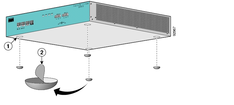
Workbench or Tabletop Installation
Figure 1-1 Tabletop Installation of the SCE 1000 Platform
For a workbench or tabletop installation, verify the following before installing the SCE 1000 platform:
•
•
•
Step 1
Step 2
![]()
![]()
![]()
![]()
![]()
![]()
![]()
![]()
Posted: Thu May 31 03:21:08 PDT 2007
All contents are Copyright © 1992--2007 Cisco Systems, Inc. All rights reserved.
Important Notices and Privacy Statement.