|
|

Table Of Contents
Single Link: Receive-only Topology
Configure GigabitEthernet Auto-Negotiation
Connect the GBE Line Interface Ports
Cable the Line Ports
This module provides instructions for cabling the Gigabit Ethernet ports and for configuring Gigabit Ethernet (GBE) interface parameters.
Note
When installing an External Optical Bypass module, the SCE 1000 line ports are connected to the module. See Appendix A in the Cisco SCE 1000 2xGBE Installation and Configuration Guide for complete instructions.
Information About Cabling
•
•
Single Link: Inline Topology
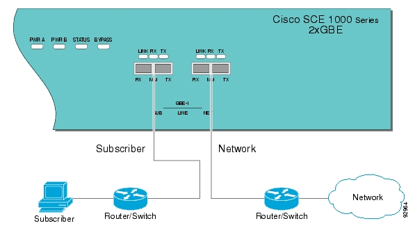
In the inline or bump-in-the-wire topology, illustrated in the diagram bellow, the SCE 1000 resides physically on the data link between the subscriber side, usually either a BRAS (in DSL access), a PDSN (in wireless access), a CMTS (in the Cable access), or a switch or router aggregator (in other topologies), and the network side, usually a router or layer 3 switch network element. This is the inline topology, providing both traffic monitoring and control capabilities.
In this topology, all the traffic of the SCE 1000 is deployed as a transparent layer2 overlay on the customer's existing network.
Figure 5-1 Bump-in-the-Wire Installation
Single Link: Receive-only Topology
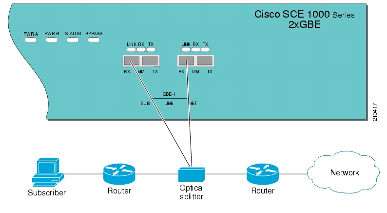
In this topology, an external optical splitter resides physically on the GBE link between the subscriber side and the network side. The external splitter is connected to the SCE 1000 via Rx links only.
In this topology, the traffic passes through the external splitter, which splits traffic to the SCE 1000. The SCE 1000, therefore, is in receive-only topology, having only traffic monitoring capabilities.
Note
Figure 5-2 External Splitting Topology
Cabling the Line Interfaces
•
•
Configure GigabitEthernet Auto-Negotiation
By default, the SCE 1000 GBE line interface ports are configured with auto-negotiation disabled.
Note
copy running-config startup-config, and press Enter.
Step 1
configureand press press Enter.Enters Global Configuration Mode.
Step 2
interface GigabitEthernet 0/portnumber, and press press Enter.Enters the GigabitEthernet Interface configuration mode for the specified GBE port.
portnumberis the number of the selected port (1 or 2).Step 3
auto-negotiateand press press Enter.Enables auto-negotiation for the GBE interface.
Step 4
exitand press press Enter.Returns to Global Configuration Mode, from which you can enter the GigabitEthernet Interface configuration mode for the remaining GBE port.
Repeat this procedure to configure auto-negotiation for the other GBE port interface.
Connect the GBE Line Interface Ports
Refer to Information About Cabling to find the appropriate cabling diagram for the topology of your system.
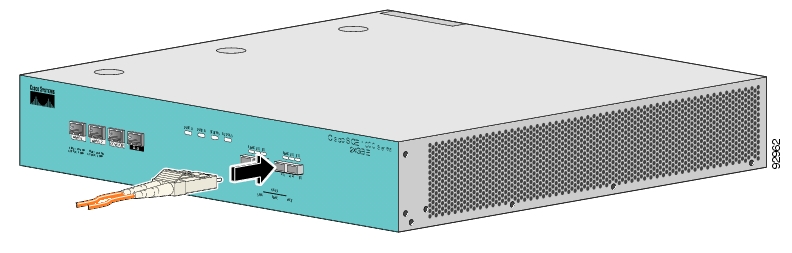
Figure 5-3 Cabling the GBE Interface
The following table presents the fiber specifications. The SCE 1000 may be ordered with either Multimode or Single Mode transceivers The transceiver type is indicated on the front panel under the ports. Note that both transceivers on any individual SCE 1000 are the same, either 850nm Multimode OR 1310 Single Mode.
Step 1
Step 2
If the link LED does not light, try removing the network cable plug and reinserting it firmly into the module socket.
![]()
![]()
![]()
![]()
![]()
![]()
![]()
![]()
Posted: Thu May 31 03:18:02 PDT 2007
All contents are Copyright © 1992--2007 Cisco Systems, Inc. All rights reserved.
Important Notices and Privacy Statement.