|
|

Table Of Contents
Overview of the Service Control Solution for MPLS/VPN Networks
Service Control in the MPLS/VPN Environment
What are the Challenges for Service Control for MPLS/VPN Support?
How the Service Control MPLS/VPN Solution Works
Service Control MPLS/VPN Concepts
Additional MPLS Pattern Support
Service Control MPLS/VPN Requirements
Overview of the Service Control Solution for MPLS/VPN Networks
•
Service Control in the MPLS/VPN Environment
•
•
•
Service Control in the MPLS/VPN Environment
MPLS/VPN networks are very complex and contain many routing protocols and many different levels of addressing and control. In addition, the various VPNs may use overlapping IP addresses (private IPs).
The SCE platform makes a distinction between identical IP addresses that come from different VPNs, and maps them into subscribers according to the MPLS labels attached to the packets. This involves various mechanisms in all levels of the system.
The following assumptions and requirements allow the SCE platform to operate in an MPLS/VPN environment:
•
•
•
–
–
•
•
Note
Definitions and Acronyms
The following table defines important terms and acronyms.
What are the Challenges for Service Control for MPLS/VPN Support?
•
•
•
•
How MPLS/VPN Support Works
Service Control supports two mechanisms that make MPLS/VPN support work:
•
•
•
Flow Detection
Flow detection is the process of deciding which packets belong to the same flow. This relates to the first two challenges listed:
•
•
Flow detection is based on the MPLS labels, extending the basic 5 tuple that SCOS uses to identify flows, and taking into account the fact that in MPLS, the packet is labeled differently in each direction.
Since MPLS traffic is unidirectional, each direction is classified separately by the SCE platform, using the following:
•
Downstream labels are learned from the control plane (BGP).
•
Upstream labels are learned from the data plane.
Subscriber Detection
What is a VPN Subscriber?
As in other modes of operation, in MPLS/VPN each flow belongs to a certain subscriber. A VPN subscriber is a customer of the Service Provider, who pays for the VPN service. All traffic of that VPN customer is aggregated into a single VPN subscriber for Service Control.
SM and Subscriber Detection
The network configuration that provides the division into VPN subscribers is controlled by the SM. The network-wide value that describes a VPN most closely is either the Route Target or the Route Distinguisher:
•
•
The relevant module in the Subscriber Manager server (SM) is the BGP-LEG. The BGP-LEG is added to the BGP neighborhood for obtaining the information on the MPLS labels. The local PEs are configured to add the BGP-LEG as a BGP peer.
•
The SM updates each SCE platform with the mapping of MPLS labels to VPN subscribers.
How the Service Control MPLS/VPN Solution Works
•
•
•
•
How the Service Control MPLS/VPN Solution Works: A Summary
•
A VPN is identified by the RD / RT and the PE.
•
•
•
•
•
SCE Platform Tasks in the MPLS/VPN Solution
•
–
–
•
•
•
BGP LEG Tasks in the MPLS/VPN Solution
•
•
•
SM Tasks in the MPLS/VPN Solution
•
•
•
–
–
•
•
Service Control MPLS/VPN Concepts
•
Non-VPN Subscribers
The MPLS/VPN solution supports the existence of non-VPN (regular IP) subscribers concurrently with the MPLS/VPN subscribers, with the following limitations and requirements:
•
•
•
In typical MPLS/VPN networks, traffic that does not belong to any VPN is labeled with a single MPLS label in the upstream direction, which is used for routing. The downstream direction of such flows typically contains no label, due to penultimate hop popping.
The SCE platform uses the one or more labels upstream and no label downstream definition to identify non-VPN flows. Classification and traffic processor load balancing on these flows is performed according to the IP header, rather than the label.
This process requires learning of the upstream labels in use for such flows, and is done using the flow detection mechanism described above (see Flow Detection ).
Bypassing Unknown VPNs
In an MPLS network, there may be many VPNs crossing the SCE platform, only a small number of which require service control functionality. It is necessary for the SCE platform to recognize which VPNs are not managed.
•
•
Note that the label limit of 57,344 different labels includes labels from the bypassed VPNs.
Each bypassed VPN entry, both upstream and downstream, is removed from the database after a set period of time (10 minutes). If the entry is still used in the traffic, it will be re-learnt. This allows the database to remain clean, even if the labels are reused by the routers for different VPNs.
In the show bypassed VPNs command, the age is indicated with each label - the length of time since it was learned.
Additional MPLS Pattern Support
The MPLS/VPN solution was designed to provide DPI services in MPLS/VPN network. These networks use BGP protocol as the control plane for the VPNs and LDP protocol for routing. There are complex networks where the MPLS infrastructure is used not only for VPN and routing, but also for other features such as traffic engineering (TE) and better fail-over. These features are usually enabled per VRF in the PE.
The Service Control MPLS/VPN solution does not support VPNs that use other MPLS-related features. Features such as MPLS-TE or MPLS-FRR (Fast Reroute) are not supported. VPNs for which these features are enabled can be automatically bypassed in the system, but are not allowed to be configured in the SM as serviced VPNs. Configuration of these VPNs in the SM might cause misclassification due to label aliasing.
The following list describes the labels combinations that are supported by the SCE platform and how each combination is interpreted by the platform:
•
Assumed to be non-VPN (see Non-VPN Subscribers ).
The SCE platform treats the following IP flows as non-VPN flows, and ignores their labels.
•
Assumed to be VPN traffic, in which the P router happens to be the last hop in the upstream.
The label in the downstream is treated as a BGP label, like the regular case. If the BGP label is known from the SM, then the flow is assigned to the correct subscriber, otherwise, it is treated as a bypassed VPN.
•
This is the typical configuration of the system. Of the two upstream labels, one is for BGP and one for LDP. The downstream label is for BGP only
•
These combinations occur when other MPLS-related features are enabled for the VPN. Such VPNs are not supported and should not be configured in the SM. However, they can be bypassed in the SCE platform without any service and without harming the service for other VPNs.
VPN Identifier (RD or RT)
Either the Route Distinguisher (RD) attribute or the Route Target (RT) attribute can be used to identify the VPN subscriber. It is required to decide which attribute best reflects the VPN subscriber partitioning, and configure the system accordingly. Note that the configuration is global for all the subscribers, that is, all subscribers must be identified by the same attribute.
The Route Distinguisher (RD) is generally used to distinguish the distinct VPN routes of separate customers who connect to the provider, so in most cases the RD is a good partition for the subscribers in the network. Since the RD is an identifier of the local VRF, and not the target VRF, it can be used to distinguish between VPN sites that transfer information to a common central entity (for example a central bank, IRS, Port Authority, etc.).
The Route Target (RT) is used to define the destination VPN site. Though it is not intuitive to define the VPN subscriber based on its destination route, it might be easier in some cases. For example, if all the VPN sites that communicate to a central bank should be treated as a single subscriber, consider using the RT as the VPN identifier.
It is important to note that this configuration is global. Therefore, if at some point in time, any VPN subscriber would have to be defined by RD, then all the other VPN subscribers must be defined by RD as well. This is a point to consider when designing the initial deployment
Service Control MPLS/VPN Requirements
•
•
Topology
Following are the general topology requirements for MPLS/VPN support:
•
•
•
•
It speaks with the SCE platform through the management IP.
In a cascade installation:
•
•
–
–
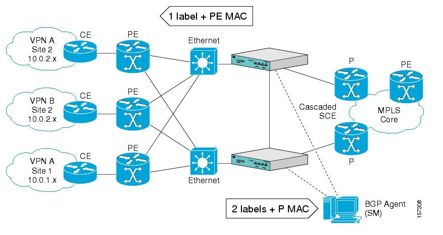
The following drawing depicts a typical cascade installation.
Figure 2-1
Capacity
The system supports:
•
•
•
•
Limitations
Mutuallyexclusive system modes
When the system works in MPLS/VPN mode, the following modes are not supported:
•
•
•
•
This provides easy configuration of MPLS/VPN. To assure correct and consistent configuration of the TOS/Tunnel-ID mode, the system does not allow configuration of TOS based rules when in tunnel-ID and vice versa
Number of MPLS labels
•
•
•
Subscriber-related limitations
The following subscriber-related limitations exist in the current solution:
•
•
•
–
–
TCP related Requirements
•
![]()
![]()
![]()
![]()
![]()
![]()
![]()
![]()
Posted: Wed May 30 08:40:04 PDT 2007
All contents are Copyright © 1992--2007 Cisco Systems, Inc. All rights reserved.
Important Notices and Privacy Statement.