|
|

This chapter describes the site requirements for installing the Cisco 6920. The chapter contains the following sections:
Before installing the Cisco 6920, assemble the equipment needed to support your network configuration and subscriber service offering. Ensure that all power and cabling requirements are met based on the equipment to install. Also ensure that environmental conditions are met to maintain proper equipment operation.
The following guidelines will help to ensure your safety and protect the equipment. This list does not cover all potentially hazardous situations, so be alert.
 |
Warning Only trained and qualified personnel should be allowed to install, replace, or service this equipment. To see translations of the warnings that appear in this publication, refer to the "Regulatory Compliance and Safety Information" section in this document. |
 |
Warning Incorrect connection of this or connected equipment to a general purpose outlet could result in a hazardous situation. To see translations of the warnings that appear in this publication, refer to the "Regulatory Compliance and Safety Information" section in this document. |
 |
Warning Ultimate disposal of this product should be handled according to all national laws and regulations. To see translations of the warnings that appear in this publication, refer to the "Regulatory Compliance and Safety Information" section in this document. |
A fully configured Cisco 6920 weighs approximately 42 pounds. This chassis is not intended to be moved frequently. Before you install the Cisco 6920, ensure that your site is properly prepared so you can avoid having to move a chassis later to accommodate power sources and network connections.
The PowerPC cards, I/O cards, input cards, and power supplies are not designed to be removed and replaced while the system is operating.
 |
Caution You must power down the system before moving or replacing any card in the Cisco 6920. |
Follow these basic guidelines when working with any electrical equipment:
 |
Warning Do not work on the system or connect or disconnect cables during periods of lightning activity. To see translations of the warnings that appear in this publication, refer to the "Regulatory Compliance and Safety Information" section in this document. |
 |
Caution Before opening the chassis, disconnect the video cables to avoid contact with any voltages. |
Electrostatic discharge (ESD) damage, which occurs when electronic cards or components are improperly handled, can result in complete or intermittent system failures. The PowerPC card, input/output cards, input cards, and DSP cards consist of a printed circuit board that is fixed in a metal carrier. Electromagnetic interference (EMI) shielding, connectors, and a handle are integral components of the carrier. Although the carrier helps protect the boards, use an antistatic strap whenever handling the PowerPC card, input/output cards, input cards, and DSP cards. Handle the carriers by the handles and the carrier edges only; never touch the boards or connector pins.
 |
Caution Always tighten the captive installation screws on the PowerPC card, input/output cards, input cards, and DSP cards. These screws prevent accidental removal, provide proper grounding for the system, and help ensure that the bus connectors are properly seated in the front plane. |
Following are guidelines for preventing ESD damage:
 |
Caution For safety, periodically check the resistance value of the antistatic strap. The measurement should be from 1 through 10 megohm (Mohm). |
To ensure normal operation and avoid unnecessary maintenance, plan your site configuration and prepare your site before installation. Take into account the following criteria:
The AC-input power supply uses a power factor corrector that allows the Cisco 6920 to operate on input voltage and frequency within the ranges of 100 through 240 VAC and 50/60 Hz.
 |
Note Cisco recommends an uninterruptible power source (UPS) to protect against power failures and power anomalies such as spikes and brown-outs at your site. The AC-input power supply has an electrical current rating of 7A. The UPS rating should accommodate startup in-rush currents in the event that the unit is power cycled; therefore, a 1500-watt plus rating is advisable per fully loaded Cisco 6920 chassis. The UPS also provides power buffering in the case of mains to generated power transfer. |
Table 2-1 lists the operating and nonoperating environmental site requirements. Within the specified ranges, the Cisco 6920 will continue to operate; however, a measurement approaching the minimum or maximum indicates a potential problem. You can maintain normal operation by anticipating and correcting environmental anomalies before they approach a maximum operating range.
The Cisco 6920 is cooled by passive conduction from the bottom through the top of the chassis. Keep the top and bottom of the chassis clear of obstructions and away from the exhaust of other equipment.
| Specification | Minimum | Maximum |
|---|---|---|
Temperature, ambient operating | 32º F (0º C) | 104º F (40º C) |
Temperature, ambient nonoperating and storage | -4º F (-20º C) | 149º F (65º C) |
Humidity, ambient (noncondensing) operating | 10% | 90% |
Humidity, ambient (noncondensing) nonoperating and storage | 5% | 95% |
Altitude, operating and nonoperating | Sea level | 10,000 ft (3,050 m) |
Planning a proper location for the Cisco 6920 and the layout of your equipment rack or wiring closet are essential for successful system operation. Equipment placed too close together or inadequately ventilated can cause systems to overheat. In addition, chassis panels made inaccessible by poor equipment placement can make system maintenance difficult. Following are precautions that can help avoid problems during installation and ongoing operation.
Follow these general precautions when planning your equipment locations and connections:
Follow these precautions and recommendations when planning power connections to the Cisco 6920:
The Cisco 6920 chassis is fully assembled at the factory; no assembly is required. However, you will need the following tools and equipment to install the chassis:
In addition, you might need the following:

 |
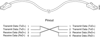
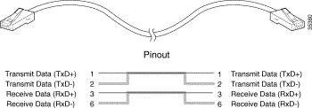
Note A 12-foot triple shielded Ethernet straight-through cable is included in the Cisco 6920 accessory box. This cable must be used for FCC compliance. |

The rack-mounting brackets on the Cisco 6920 are suitable for most 19-inch equipment racks. Before using a particular rack, check for obstructions (such as a power strip) that could impair rack-mount installation. If a power strip does impair a rear rack-mount installation, remove the power strip before installing the chassis in the rack, then replace it after the chassis is installed. Note that you cannot mount the Cisco 6920 on an equipment shelf because the bottom and top of the chassis must be free from obstructions so that air can circulate through the unit.
In addition to the preceding guidelines, review the precautions for avoiding overtemperature conditions in the "Site Requirements" section. To properly install the Cisco 6920 chassis in a rack, refer to the instructions in the "General Installation" section on page 3-3.
 |
Caution To prevent the chassis from overheating, never install the Cisco 6920 in an enclosed rack or room that is not maintained within ambient operating temperatures by proper room ventilation or air conditioning. The unit will overheat if the conducted input air temperature reaches 105º F (41º C). |
This section describes considerations for setting up the cabling at your site. When planning the location of the new system, consider the distance limitations for signaling, EMI, and connector compatibility, as described in the following sections.
When wires are run for any significant distance in an electromagnetic field, interference can occur between the field and the signals on the wires. This fact has two implications for the construction of headend wiring:
If you use twisted-pair cable in your headend wiring with a good distribution of grounding conductors, the wiring is unlikely to emit radio interference. If you exceed the recommended distances, use a high-quality twisted-pair cable with one ground conductor for each data signal when applicable.
If wires exceed recommended distances, or if wires pass between buildings, give special consideration to the effect of a lightning strike in your vicinity. The electromagnetic pulse caused by lightning or other high-energy phenomena can easily couple enough energy into unshielded conductors to destroy electronic devices. If you have had EMI problems in the past, you might want to consult experts in electrical surge suppression and shielding.
DHEI cables should not be longer than 10 feet.
 |
Note Cisco recommends that you do not exceed specified transmission rate and distance limits. |
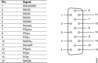
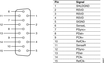
Figure 2-3 and Figure 2-4 show the signal-to-pin designations for the DHEI input and output connectors.


![]()
![]()
![]()
![]()
![]()
![]()
![]()
![]()
Posted: Thu Mar 29 17:07:06 PST 2001
All contents are Copyright © 1992--2001 Cisco Systems, Inc. All rights reserved.
Important Notices and Privacy Statement.