|
|

Product Number: GES20W05V0104
December 15, 2000
This document describes the Uninterruptible Power Supply (UPS) for the Cisco CVA120 Series Cable Voice Adapter and how to install the UPS, replace its battery pack, and prepare it for storage.
 |
Caution This UPS must be used to power only a Cisco CVA120 Series Cable Voice Adapter. |
The UPS for the Cisco CVA120 Series Cable Voice Adapter provides a backup power supply for the cable voice adapter and the telephones attached to it. The UPS has the following specifications and features:
 |
Caution For protection against risk of fire, replace only with the same type and rating of fuse. |
 |
Caution DISCONNECT POWER BEFORE CHANGING THE FUSE. |
| Normal (Green) | Warning (Amber) | Description |
|---|---|---|
| OFF | OFF | Power OFF, Battery Pack is Discharged, or Hardware Failure:
Plug the UPS into an AC power source. If the Normal LED does not light, check the fuse and replace if necessary. If the Normal LED still does not go on, replace the UPS. |
| ON | OFF | Normal Mode—The UPS is connected to AC power and charging its battery pack. |
| ON | ON | Battery Backup Mode—AC power to the UPS has failed and the UPS is powering the cable voice adapter with its internal battery pack. |
| ON | Blinking | Low Battery, Defective or Missing Battery Pack:
|
| Blinking | Blinking | Severe Fault—The UPS is experiencing a current overload, possibly caused by the AC power source or cable voice adapter. Immediately disconnect the UPS from AC power and the cable voice adapter. Investigate whether the AC power source, cable voice adapter, or UPS is causing the problem. Replace the defective unit. |
| 1Call the number on the bottom label of the UPS chassis for battery pack disposal and replacement. |
Follow these guidelines when working on equipment powered by electricity.
If mounting the UPS on a wall, you will require a drill, 1/8-inch (4 mm) drill-bit, and four 1/8-inch (4 mm) wood screws or wall anchors (depending on wall material), at least 1-inch (25 mm) in length.
To wall-mount the UPS, do the following:
Step 2 Drill four holes that are 3/4-inch (19 mm) deep. The holes should be arranged in a square that is 3-15/16 inch by 3-15/16 inch (100 mm by 100 mm), to match the mounting holes on the UPS chassis:

Step 3 Install the four screws in the mounting holes, according to the instructions accompanying them. The screw heads should extend approximately 1/4-inch (6.5 mm) from the surface of the wall.
Step 4 Position the UPS either vertically or horizontally as shown:

Step 5 Align the mounting holes on the underside of the UPS with the mounting screws and push the UPS against the wall, making sure that the UPS is securely inserted onto each screw. Pull the UPS down to lock it against the screws.
To connect the UPS to the Cisco CVA120 Series Cable Voice Adapter:
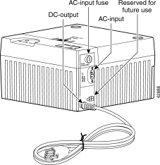
Step 2 Plug the eight-pin connector (shown as "DC-output" in the following figure) into the eight-pin plug on the rear panel of the cable voice adapter. Push the connector in until it locks.

Step 3 Insert the plug end of the supplied power cable into the power connector on the UPS chassis (shown as "AC-input" in the figure above).
Step 4 Plug the other end of the power cable into a suitable AC wall outlet.
When you plug the UPS into an AC power source, the green LED labeled "Normal" lights to indicate that AC power is present. Connecting the UPS to AC power automatically activates the internal battery pack, so that if AC power is then lost, the UPS immediately begins providing power to the cable voice adapter.
Under normal circumstances, the CVA120 Series UPS does not need any maintenance. However, if you need to replace the battery pack within the UPS, use the following procedure.
Step 2 Remove the UPS from its wall-mount (if applicable) and place it on a firm, flat surface.
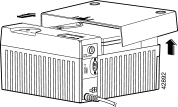
Step 3 Face the front of the UPS chassis and using both hands, push down on the button marked "PUSH TO OPEN." Lift up to remove the cover, as in the following figure: 
Step 4 First remove the positive (red) lead from the battery, and then remove the negative (black) lead from the battery pack. See the following figure: 
Step 5 Lift the old battery pack out of the UPS chassis, and place it aside for disposal.
 |
Note The battery pack is a sealed lead battery and must be recycled. For recycling information inside the USA call 800-738-7372. Outside the USA call 1-817-244-7777. |
 |
Warning Ultimate disposal of this product should be handled according to all national laws and regulations. (To see translations of this warning, see the appendix, "Translated Safety Warnings," in the CVA User Guide.) |
 |
Caution There is a danger of explosion if the battery pack is incorrectly replaced. Replace only with the same or equivalent type, as recommended by the manufacturer. |
Step 6 Insert the replacement battery pack into the chassis, with the battery terminals at the left side of the chassis as you face it. The spacer should be near the back of the chassis.
Step 7 Attach the negative (black) lead to the terminal closest to the front of the UPS chassis. Make sure that the lead slides all the way on to the terminal and is securely connected.
Step 8 Attach the positive (red) lead to the terminal furthest from the front of the UPS chassis. Make sure that the lead slides all the way on to the terminal and is securely connected.
Step 9 Replace the cover by positioning over the chassis, with about a 1/2-inch gap between the cover and chassis, and push down and pull forward until it snaps shut. Be careful not to hit or dislodge the cables going to the battery terminals.
Step 10 Replace the UPS in its normal position or wall-mount, and reconnect the cables to the cable voice adapter and wall power outlet.
The UPS is shipped from the factory in an inactive state, and its battery backup circuitry does not activate until the UPS is plugged into an AC power source for the first time. This prevents the battery pack from discharging while in storage and transit. Before returning the UPS to storage, use the following procedure to return the UPS to the inactive state so that it does not continue to discharge its battery pack:
Step 2 Disconnect the UPS from the AC power. This should turn on the Warning LED, indicating that the UPS has gone into battery backup mode.
Step 3 Disconnect the UPS from the cable voice adapter.
Step 4 Face the front of the UPS chassis and, using both hands, push down on the button marked "PUSH TO OPEN." Lift up and remove the cover to expose its internal battery pack.
Step 5 Remove the positive (red) lead from the battery; the Warning LED should go off. Wait at least ten seconds and then reconnect the lead. The Warning LED should remain off.
Step 6 Replace the cover on the UPS. The UPS can now be stored for an extended period of time without affecting the battery life or power output.

![]()
![]()
![]()
![]()
![]()
![]()
![]()
![]()
Posted: Wed Dec 27 01:02:12 PST 2000
Copyright 1989-2000©Cisco Systems Inc.